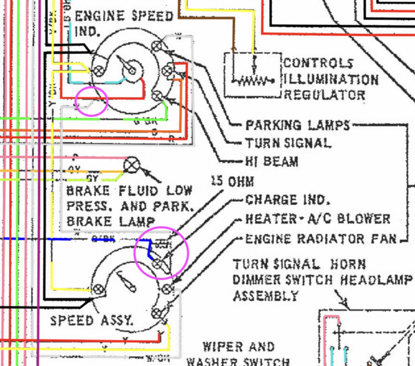
The wiring diagram below shows the charge indicator light wiring. Magenta circles show a white wire connected to the tach +12v (red) wire and extends to the charge indicator bulb socket in the speedo. The other terminal of the socket connects to a blue / black wire that extends into the engine compartment and will connect to the green / red stripe wire from your alternator.
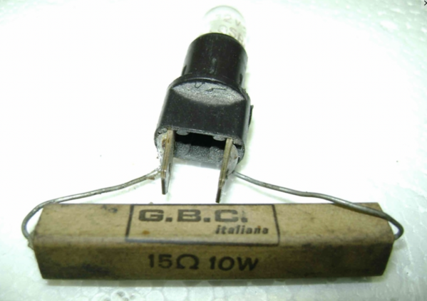
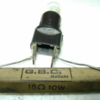
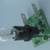
The Charge indicator's bulb socket is a TWO terminal socket. It does NOT ground the light bulb. There is a 15 ohm, 10 watt resistor soldered across the socket's two terminals. In normal operation, this resistor gets very warm, usually too hot to touch.
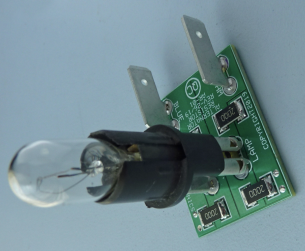
As an alternate to the above socket and resistor cludge, Pantera Electronics offers a modern replacement which can use either an incandescent bulb or an LED bulb.
John


