

PART 5 - INDUCTION SYSTEM (volumetric efficiency)
Feeding air and fuel to an 8 cylinder engine via a single carburetor is efficient in terms of cost and simplicity but a bad design in terms of high performance. Cylinder to cylinder consistency of the fuel air mixture is difficult to achieve with a single carburetor, and it is greatly influenced by intake manifold design. The manifold design must insure that equal amounts of air and fuel are flowing into each cylinder, it must not do anything that may cause the fuel to fall out of suspension, and it should prevent or control fuel puddling. The quality of the fuel air mixture is greatly influenced by carburetor design. Improved atomization of fuel (smaller fuel particles) insures the fuel stays in suspension, distributes more equally cylinder to cylinder, and ignites more readily in the combustion chamber. This is one reason why you shall find I emphasize the use of carburetors with annular booster venturis.
An individual runner induction system alleviates these concerns. An individual port fuel injection system employing a manifold with long equal-length runners also alleviates these concerns. A throttle body fuel injection system mounted on an intake manifold originally designed for a carburetor atomizes the fuel excellently, but it does not alleviate the concern for cylinder to cylinder consistency, fuel puddling, etc. I shall touch on these alternatives in this section.
Things we can do to improve the performance and/or volumetric efficiency of the induction system include increasing the size of the carburetor, improving the calibration of the carburetor, selecting a carburetor which atomizes fuel better, improving air/fuel mixture flow through the intake manifold, smoothing the intake ports, grinding 3 angle intake valve seats, improving the camshaft lobe profile, and increasing valve lift.
In practical terms those things boil down to a larger carburetor with annular booster venturis, an aluminum intake manifold (Ford, Edelbrock, Blue Thunder) or reworking the factory cast iron intake manifold to accommodate the larger carburetor, and a camshaft that lifts the valves further open with matching valve train improvements. Key valve train improvements include single groove stainless steel valves, higher rate valve springs, stiffer-thick wall push rods, and improvements to the factory rocker arms. The subject of valve train improvement shall be discussed in additional detail in the valve train section which follows this section.
SINGLE FOUR BARREL CARBURETOR INDUCTION
Four Barrel Carburetors
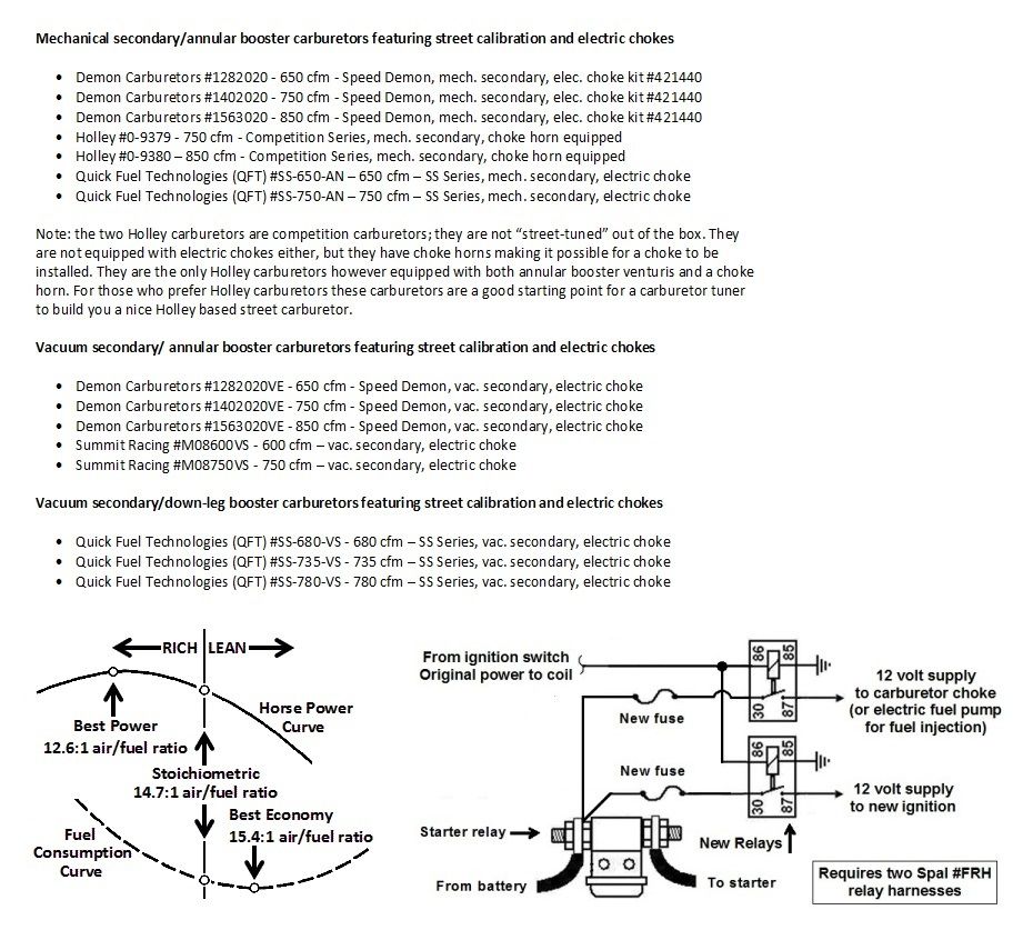
At 6000 rpm a 351 cubic inch motor would theoretically inhale 609 cubic feet of air per minute if the volumetric efficiency were 100%. At 7000 rpm the same motor would inhale 710 cubic feet of air per minute assuming 100% volumetric efficiency. Assuming 90% volumetric efficiency a 351 cubic inch motor will inhale air at the rate of 548 cfm at 6000 rpm or at the rate of 639 cfm at 7000 rpm.
However, as the volumetric efficiency of a motor improves the intake manifold vacuum at wide open throttle shall decrease. The intake manifold pressure of a motor with 100% volumetric efficiency is theoretically equal to atmospheric pressure at wide open throttle. The airflow rating of carburetors is measured at a fixed depression, such as 1.5 inches of mercury in the case of Holley carburetors. If the depression across a Holley carburetor is less than 1.5 inches of mercury at wide open throttle it will not flow the amount of air it is rated at, the motor shall require a carburetor with a larger rating than what we calculated in order to supply adequate airflow at 6000 or 7000 rpm. The reason for this is not because the motor demands more air flow than what we calculated but because the carburetor, which is rated at a depression of 1.5 inches of mercury, flows less air if the depression is less than 1.5 inches of mercury; in other words the flow rating of a carburetor as determined at 1.5 inches of mercury becomes less relevant as the volumetric efficiency of a motor increases. For any given quantity of air flowing into the engine a larger carburetor will require less intake manifold vacuum to supply that quantity of air, therefore the intake manifold vacuum at any given rpm shall be less and this allows for higher volumetric efficiency.
Both the 351C 2V and the 351C 4V have higher volumetric efficiency than the popular in-line-valve V8s people are more familiar with; at wide open throttle the vacuum in their intake manifolds will drop lower than it does in those other V8s if the carburetor is large enough to allow it. This is the reason larger carburetors are recommended for the Cleveland engine series. If an owner selects parts for the 351C induction system following the same guidelines people follow when selecting parts for a SBC or SBF the 351C shall not perform any stronger than a SBC or SBF; the superior volumetric efficiency for which the 351C is known shall be quenched. Contrary to the carburetor sizing conventions you may be familiar with the 351C (especially the 4V version) is designed to inhale more air than other engines and it responds well to a bigger carburetor. There is no penalty in drivability or throttle response as long as the carburetor is calibrated properly.
On top of that the 351C 4V is capable of operating over an extraordinarily wide power band, certainly wider than any other OHV engine from its era. The first 351C 4V performance manifolds designed by Ford were designed for list #4575 Holley Dominator carburetors (1050 cfm)! Ford’s earliest carburetor recommendations also included the Holley 850 cfm double pumper. The 351 Cleveland engines require carburetors designed for engines having higher volumetric efficiency and in the case of the 351C 4V a wide power band too. The usual carburetor choices for a 351C 2V usually range from 650cfm to 750cfm; for the 351C 4V those choices usually range from 750cfm to 850cfm. None of these carburetors are too big for a 351C street motor, especially if they are equipped with annular booster venturis. With a 351C 4V street motor it is a challenge to find a carburetor that performs well at low rpm while also being large enough to take advantage of the WOT (wide open throttle) volumetric efficiency of that motor.
Annular booster venturis atomize fuel better and provide a stronger fuel metering signal at low air velocity. In other words, annular booster venturis benefit the low rpm and mid-rpm performance of a motor in the same manner as the smaller primary throttle bores of a spread bore carburetor. These attributes make annular booster venturis popular for improving the low rpm operation of performance engines, where they have earned a reputation for improving torque, horsepower and throttle response at low engine speeds. However the improvement in fuel atomization distributes fuel more consistently throughout an intake manifold, resulting in more consistent fuel/air ratio from cylinder to cylinder, therefore annular booster venturis actually improve torque and horsepower across a motor's entire power band; and they improve fuel economy too! The only drawbacks of annular booster venturis include their larger physical size (which reduces the airflow capability of a carburetor by a relatively small amount) and their greater cost of manufacture.
If an owner selects a smaller carburetor it’s not the end of the world. A 600 cfm to 650 cfm carburetor is fine for daily transportation purposes and even a playful bit of acceleration from time to time. But I don't recommend that choice for the performance minded owner. A 351C equipped with a smaller carburetor will flatten out sooner when accelerating and lose the eagerness to rev far beyond 6000 rpm. The smaller carburetor may lower the rpm at which peak horsepower occurs and it shall definitely impair the engine’s volumetric efficiency.
The most important aspect of any carburetor is not its size but how well it has been calibrated to suit your car’s motor. Regardless of what size carburetor you choose, if it is calibrated poorly the motor shall perform poorly, if it is calibrated well it shall perform well. An engine equipped with a well calibrated 600 cfm carburetor will make more horsepower than if it were equipped with a poorly calibrated 750 cfm carburetor; but if the 750 cfm carburetor is calibrated as well as the 600 cfm carburetor then the motor will perform better with the larger carburetor. It is rare to find an out-of-the-box carburetor that is calibrated 100% ideally for your application. For this reason many enthusiast prefer a carburetor having features that make it easier to tune.
Single Plane 351C Intake Manifolds
Under Development
Dual Plane 351C Intake Manifolds
A dual plane intake manifold is the best choice for a street driven vehicle in terms of overall functionality and usable performance. Most dual plane intake manifolds will blunt an engine’s power in the upper rpm region, but they improve a motor’s “grunt” at low rpm, they improve drivability and they perform best in the rpm range encountered 90% of the time when driving on public roads. Dual plane intake manifolds usually improve vacuum at idle by at least 50%; achieving the best possible manifold vacuum allows the positive crankcase ventilation system (PCV), the distributor vacuum advance mechanism, and the power brake vacuum booster to all work within their intended design limits for best possible operation (automatic transmission vacuum modulators too).
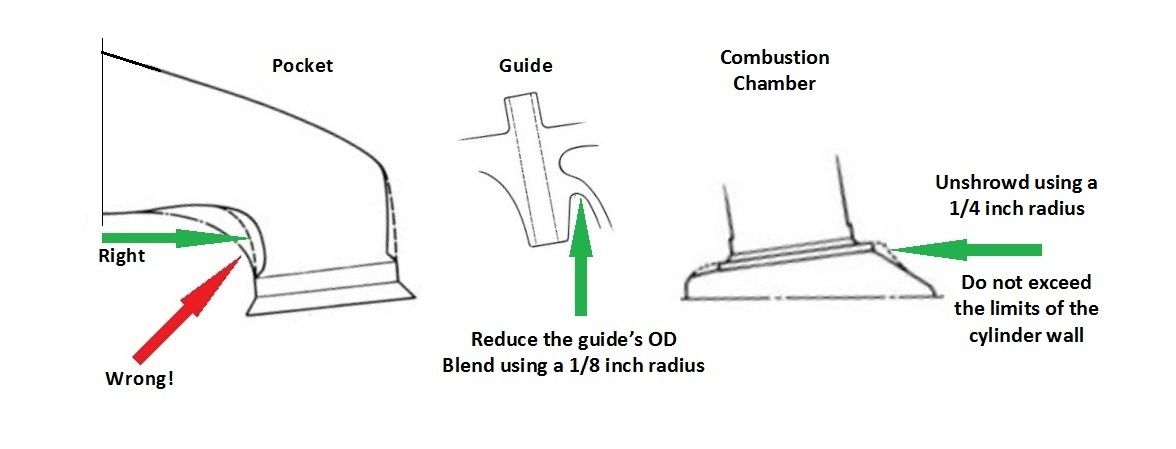
The 4V intake port entrance is about 2-1/2" tall, yet the runners in the factory intake manifolds are not nearly that tall, they are closer to 2" tall. The factory intake manifold runners flare open to match the height of the 4V intake port entrance. The gas flow in the factory induction system starts in a runner with a cross sectional area of about 3 square inches, then it expands to a cross sectional area over 4 square inches at the intake port entrance, then past the intake port entrance it returns to a cross-sectional area closer to 3" again. This is not ideal. One way to achieve an induction system having a more consistent cross-sectional area is to use the Blue Thunder manifold which has full height runners that complement the opening of the 4V intake port; the Blue Thunder manifold was designed to be a "wide open induction system" manifold thus complimenting the engineering of the 4V intake port, it performs very well with the iron 4V heads.
Like the factory intake manifolds, the runners of the Edelbrock Performer manifold and Scott Cook’s dual plane manifold are about 2” tall; however the runners of the Edelbrock and Scott Cook manifolds do not flare open, they are designed to achieve a more consistent cross-sectional area; therefore the runners are smaller than the 4V intake port entrance. Those manifolds can be mated to the 4V heads as-is. Do not blend the runners of the manifolds to match the opening of the 4V intake port; they perform better if they are not blended. If you wish to eliminate the mismatch and make the cross sectional area more consistent the proper way to do so would be to fill the inlet of the 4V intake port to match the Edelbrock or Scott Cook manifold runners (this is also called stuffing the intake port). Filling the inlet of the intake port about 1/8" on the left side, and about 1/2" on the floor, gives the intake port a more consistent cross-sectional area (the average cross-sectional area is reduced from 2.9 square inches to about 2.7 square inches) and makes the port smoother, eliminating the push-rod bump and ramped floor built into the port’s entrance. Of course, Scott Cook’s cylinder heads feature stuffed 4V intake ports out of the box.
One warning however, the 4V intake port was intentionally flared open, creating the ramped floor and push-rod bump at the port’s entrance, in order to incorporate features which increase air flow within the port. In spite of the fact they create an irregularly shaped port the features work very well at increasing flow. Intake manifolds which lift the gas flow within the port so as to avoid these features may actually result in a decrease in gas flow or engine performance. Stuffing the port will definitely decrease gas flow. If you're going to stuff the port entrance then the port should be "ported" further within afterwards to regain the lost port volume, to make the ports cross-section and shape smoother and more consistent, and to regain the flow that was lost by stuffing it. The port actually works very well "as-is", it doesn't require "fixing". This is why I recommend the Blue Thunder manifold which allows the intake port to operate optimally in the way it was originally designed to do so.
Fuel Supply System
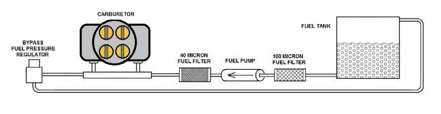
It’s very likely the fuel supply system of your car’s engine will also require reworking in order to supply sufficient fuel for the motor’s higher output. The Robb Mc Performance #1020 mechanical fuel pump is rated for up to 550 horsepower. Plumb the fuel system in metal tubing as much as possible, keep the hose sections as short as possible, use a tubing bender to put smooth large radius bends in the metal tubing, avoid 90° tubing fittings. Plumb the pump suction in ½” (AN-8) tubing or hose and plumb the pump discharge in 3/8” (AN-6) or ½” (AN-8) tubing or hose. Install a high flow fuel "pre-filter" designed for the fuel pump inlet (75 to 150 micron) and install a high flow fuel "post-filter" designed for the fuel pump outlet (10 microns for fuel injection or 40 microns for a carburetor). RobbMc Performance
Pantera owners: the tubing in the fuel tank that supplies the fuel pump is only 5/16" OD; this is much too small. If you're building a high output motor for a Pantera, this is one item that shall require modification. Upgrade it to 1/2" tubing.
The picture below details the proper way to plumb a fuel system using an electric fuel pump for both carburetors or fuel injection.
INDEPENDENT RUNNER INDUCTION
Another induction system modification worth mentioning is an independent runner induction (often abbreviated IR) composed of a Weber 48IDF intake manifold manufactured by Aussie Speed of Australia and four Weber 48IDF two barrel down draft carburetors. The Aussie Speed manifold is designed as a 2V manifold, but it is also designed to seal-up the larger intake port openings of a 4V cylinder head.

The Weber IDF carburetor is Weber’s most popular two barrel down draft carburetor for racing, high performance automobiles and sports cars. It has been used as OEM equipment in a few limited production vehicles, including a Ford Escort (the European Ford Escort RS2000 Group 1 cars). It is accepted by very many sports car hobbyists as a suitable replacement for various Delorto and Solex carburetors. Like the side draft Weber DCOE carburetor, the Weber IDF carburetor is sold by Pegasus Racing, which is an indicator of the carburetor’s popularity. There is no demand for Weber’s other two barrel down draft carburetor, the IDA carburetor, outside of the American muscle car niche market. Weber's IDA carburetor is not as well suited for street applications as their IDF carburetor.
The IDF carburetor is offered in 40, 44 and 48 mm bore sizes. The main, idle, air correction and accelerator pump jets, the emulsion tubes and venturis, are interchangeable. It has a float design that makes it very popular for off-road applications, a vacuum advance port, and four progression holes for smooth light-accelerator response. The differences between the IDA and the IDF, like two additional transfer circuits, add up to make a big difference in the IDF’s part-throttle performance and its suitability as a carburetor for a year-round daily-driver application.
An IR induction such as this is more expensive to purchase, it is more time consuming to tune, and it often requires more frequent maintenance. However, in comparison to a single four barrel carburetor induction system the benefits of an IR system include quicker throttle response, faster acceleration, a wider power band and substantially improved volumetric efficiency. Aussie Speed
FUEL INJECTION
Fuel injectors atomize fuel better than a carburetor at low engine speeds and normally account for a 10% to 15% improvement in torque at low rpm. Port fuel injection also eliminates the issues of fuel falling out of suspension, fuel puddling, and uneven fuel distribution associated with intake manifolds designed for carburetors.
Throttle body fuel injection shall always be a viable option for retrofitting fuel injection to an older engine in terms of simplicity, cost and stealth because it can be installed in place of an existing carburetor, and therefore it does not require the replacement or modification of an intake manifold, it takes up no more room in the engine compartment, and it even uses the same air filter assembly.
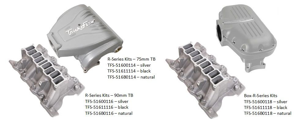
However the big news in fuel injection for the 351C is the two port-fuel injection intake manifold kits manufactured by Trick Flow® Specialties. Both of these intake manifold kits are an overwhelmingly better way to fuel inject a 351C in terms of performance compared to utilizing an intake manifold designed for a carburetor.
The R-Series intake is a long equal length runner design which is tuned for high performance street engines. Combining long equal length runners with the improved fuel atomization at low rpm typical of fuel injectors this manifold has the potential to boost the lower rpm power of a 351C much in the same way this type of manifold boosted the lower rpm power of the 5.0 HO V8 in the 1980s. This manifold provides a superior way to achieve the type of low rpm grunt that people are trying to duplicate when they build stroker engines. The R-Series intake manifold is claimed to have 13.3” long runners and an overall height of 11.000 inches. It is available with either a 75mm throttle body inlet or a 90mm throttle body inlet.
The Box-R-Series intake features a large plenum/short equal length runner design which maximizes mid-to-high-rpm power making it ideal for racing applications. This manifold has the potential to improve volumetric efficiency like an individual runner induction system but only requires one throttle body. The Box-R-Series intake manifold has a 90mm throttle body inlet, and an overall height of 12.000 inches.
Both Trick Flow® EFI manifold uppers are offered in a choice of silver and black powder coated finishes or natural aluminum which allows the customer to finish the manifold as they prefer. The common base used for these manifold kits is finished in bare aluminum, the port outlets are 2.100 inch x 1.500 inch at the cylinder head; and it is designed to bolt up to both 2V and 4V cylinder heads. Trick Flow Specialties
CYLINDER HEAD PORTING AND PORT STUFFING
You may consider having some minor work performed on the heads ... pocket clean-up and 3 angle valve seats, plus a little work in the roof and sides of the exhaust port. Its hard to give guidance regarding selection of a business to port 4V cylinder heads in broad terms. Do not agree to extreme porting of the 4V heads unless the business has a decades old reputation for porting 351C 4V cylinder heads; such as Koontz and Company (Arkadelphia Arkansas) or Valley Head Service (Northridge California). Most "cylinder head porting businesses" do not understand the 4V heads. I've seen 351C 4V performance worsened by many businesses claiming to be professionals at cylinder head porting. It is healthy to be hesitant and cautious about handing over your 4V cylinder heads to any business for modification. A simple amount of pocket and port clean-up combined with 3 angle valve seats will increase air flow through both the intake and exhaust ports by 50 cfm at 0.600" valve lift.
More to Come - Under Development

PART 6 - EXHAUST SYSTEM
Things we can do to improve the exhaust system include increasing valve lift, improving the camshaft lobe profile, grinding 3 angle exhaust valve seats, smoothing and moderate porting of the exhaust ports, installing steel tubing headers and an unrestrictive (low back pressure) exhaust system. A low back pressure exhaust system includes 2-1/4” to 2-1/2” intermediate pipes (with an H-type or X-type cross-over if possible), free flowing mufflers, and tail pipes that are as short as possible (dumping ahead of the rear tires in front engine cars). An exhaust system can only perform as well as its weakest link. As mufflers become less restrictive the gains that can be realized by improving other aspects of the exhaust system multiplies. The higher the output of an engine the higher the gains that may potentially result from exhaust system improvements.
STEEL TUBING HEADERS
The first rule of thumb: the inside diameter of the primary tubes should be approximately 110% the diameter of the exhaust valve. That rule of thumb equates to headers with 1-7/8” to 2” primaries for iron 4V heads or 1-3/4” primaries for all other heads. Another rule of thumb: low rpm power is usually improved by smaller and longer tubes & high rpm power is usually improved by bigger and shorter tubes. The design of the “collector” is also very important.
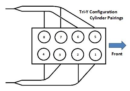
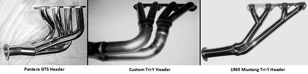
Standard “4 into 1” steel tubing headers should feature primary tubes of reasonably equal length, they should be made of tubing of the proper diameter and functional length, they should be shaped with no sharp bends, and they should terminate into a properly designed collector. 180 degree exhaust systems (aka bundle of snakes exhaust systems) combine primary tubes from both banks of cylinders based on the engines firing order, in order to achieve the maximum possible separation between exhaust pulses in each collector. The goal is to broaden the tuning of the exhaust system thus improving mid-range power over a wide range of engine speed. Tri-Y headers (aka 4 into 2 into 1 headers) pair the cylinders on each bank of the engine so as to provide the maximum separation between exhaust pulses per bank. It is a more practical design for achieving performance goals similar to a bundle of snakes type exhaust system without taking up as much engine compartment space. With a Tri-Y header I've been told the SECONDARY tubes are a more important design aspect than the primary tubes. In other words when space is limited it is better to shorten the primary tubes and lengthen the secondary tubes.
After those considerations the most important aspect of header design (and the exhaust system as a whole) is the tubing geometry; i.e. construction details such as bend radii, intersection angles, nozzle angles, and diffuser angles. These details have a tremendous impact on the performance of the exhaust system. Any header (and exhaust system) has to make concessions in its construction to clear various parts of the chassis, the suspension, the steering, the starter motor, the bell housing or the transmission. Each one of those concessions also has the potential to inhibit the theoretical pulse and reflection behavior of an exhaust system and negatively impact the exhaust system's performance; thus a “real world" exhaust system does not always perform as well as expected. One particular aspect of header geometry was discovered long ago to greatly impact the performance of the 351C 4V exhaust port ... the 4V exhaust port works better if the primary tubes extend straight out of the head as far as possible.
Pantera Exhaust
The Pantera chassis does not provide enough space for headers with primary tubes of the proper length. Nor does it provide enough space for decent mufflers. It is possible to install a cross-over under the car connecting the left and right sides of the exhaust system, but it is almost as long as the intermediate pipes! The one good thing about the Pantera chassis, it allows enough space on either side of the engine so the primary tubes can extend straight out of the head for several inches.
The European GTS exhaust system should be considered a minimum upgrade for Panteras equipped with the "small tube" factory exhaust system. The GTS system is reasonably quiet, with a nice low frequency burble. The price of the system is reasonable, it’s easy to install and it has the all important factory look. The headers have the proper size primaries for iron 4V heads and the header flanges are nice and thick. They are designed as a "pseudo-Tri-Y" header lacking secondary tubes! The single collector is also too small. But surprisingly the headers perform better than they have any right to do so. The intermediate pipes are made of thick wall 2-3/8" OD steel tubing, they weave their way through the Panteras suspension perfectly. The system's biggest drawbacks are the mufflers which impact horsepower output above 5500 rpm. To work best with the Ansa mufflers your Pantera's motor should employ a camshaft with limited overlap (50° to 62°) which opens the exhaust valve early (80° BBDC or earlier).
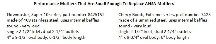
The spaces provided for mufflers in the narrow body Panteras are only 10” x 10”, but the wide body Panteras have room for mufflers up to 16" in length because the rear tires are spaced outwards. I am not aware of a quiet, free breathing replacement for the restrictive, 9-1/2" x 9-1/2" Ansa mufflers, but there are two loud universal aftermarket mufflers that will fit in the same small spaces:
PART 7 - CAMSHAFT AND VALVE TRAIN
The large and heavy 351C 4V intake valve, the high ratio (1.73:1) rocker arm, and the canted valve geometry which splays the pushrods apart at extreme angles, constitutes one of the toughest valve train applications of any OHV engine. 500 to 570 horsepower was pro-level horsepower for any size endurance racing engine when the 351C was designed. In those days valves lifted off their seats by 0.550” to 0.600" was state of the art for a pro-level endurance racing engine. Although that's standard valve lift for a modern street performance cam, in the early 1970s solid flat tappet racing cams having 0.550” to 0.600" valve lift were very long duration - high overlap camshafts which pushed the limits in race engine performance and reliability. The valve train performance of our modern street engines was achieved via advancements in successive generations of camshaft grinding machinery and it was made usable by advancements in valve spring technology.
If you dramatically improve the valve train performance of your 351C engine, you have to assume you cannot take any short-cuts in the quality of the valve train componentry you select. Keep in mind your engine's modern valve train may be lifting the valves off the seats as much as racing cams did 40 years ago, with less camshaft lobe duration, and with hydraulic tappets rather than solid tappets!
The performance of the 351C 4V can be described as having good drivability, a strong dose of mid-range power, and the willingness to rev to high rpm. As I stated previously I consider this characteristic ideal, it is something I try to avoid diminishing in any aspect when I tune the engine for higher output. The camshaft plays a major role in that.
The other small block in-line valve motors people are more familiar with have small ports and small valves for the given displacement of the motor, thus pushing the motor’s power band into the very lower end of the rpm range. Such motors rely upon long duration camshafts and high rpm intake manifold design to widen the power band and promote mid and upper rpm power. The 351C 4V is just the opposite, the intake ports and valves were sized to give the motor a power band that peaks at approximately 6000 rpm and pulls strong out to 6500 rpm and in some cases even as high as 7000 rpm. The 351C 4V relies upon camshaft design (moderate valve event timing) and intake manifold design (dual plane) for its lower rpm performance. The wide and flat 351C 4V power band/torque curve was quite good for street performance off the show room floor, the power band simply does not need to be altered or raised.
351C 4V FACTORY CAMSHAFTS
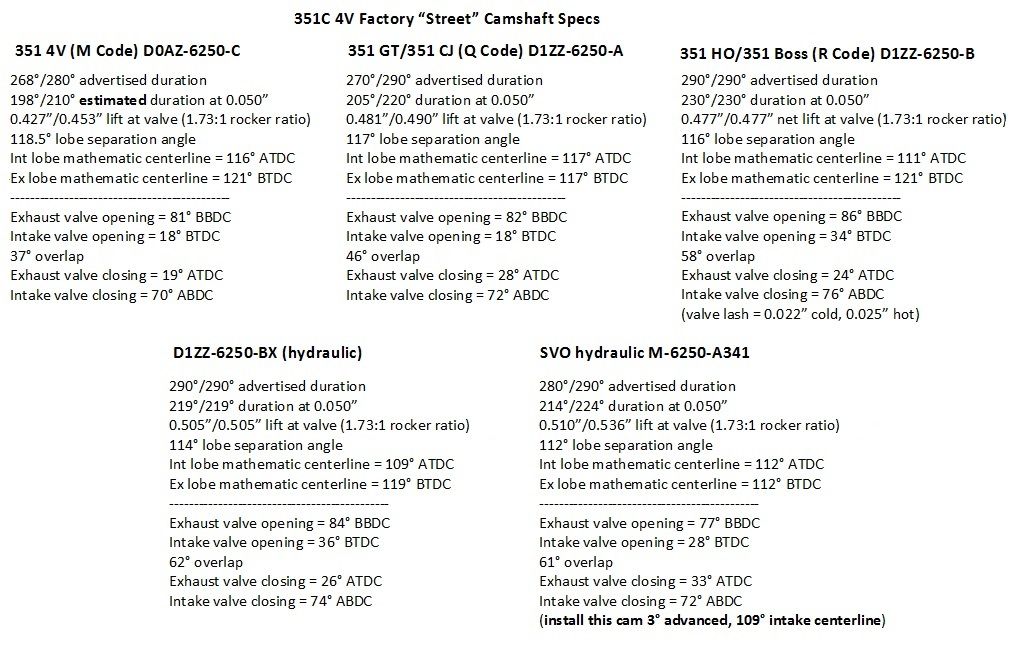
If you're interested in one of the Ford camshafts, three of them are still available via the aftermarket.
HIGH LIFT RATE CAMSHAFTS
In selecting a camshaft to improve the induction system the goal is to find a camshaft which lifts the valves higher via higher-lift-rate lobes without straying too far from the factory camshaft timing. Straying too far from that timing will erode the engine’s good low rpm performance and drivability. The short intake duration of the factory camshafts proves a 351C with 4V heads does not need a lot of intake duration to have a high revving power band.
There are four common camshaft design errors that are made in regards to valve event timing that make things worse in regards to 351C 4V street performance:
- Opening the exhaust valve too late causes high rpm torque to fall-off like a brick if there is any exhaust system back-pressure (mufflers). You can see from the factory cam specs the engine likes the exhaust valve to open by at least 80° BBDC. The SVO cam, which opened the exhaust valve a little later (77° BBDC), had a power band that was known to flatten out early. This is one reason why I've made a note about installing the cam advanced.
- Too much over-lap softens low rpm torque, makes the engine idle rougher, and decreases vacuum at idle. None of the factory cams have more than 62° overlap. The big intake valve and canted valve geometry of the 351C 4V increases the interaction between the exhaust port, the combustion chamber, piston motion, and the intake port during the overlap period. This is a good thing for a race engine, overlap can be used to scavenge exhaust gases and get the intake charge flowing early which improves volumetric efficiency. Drivability (i.e. performance below 3000 rpm) isn't important to a race engine. While amplifying the effects of overlap is a good thing for a race engine, its a bad thing for a street engine. Small increases in overlap quickly diminish the drivability of an engine equipped with 4V cylinder heads. It is not the size of the intake port that hurts low rpm performance and drivability as people often assume, its the size of the intake valve and the manner in which it amplifies the effects of overlap. In designing or selecting a 351C 4V street camshaft its important to place emphasis on minimizing overlap in order to optimize low rpm power and maintain drivability.
- Narrow lobe centerlines (LSA) create the first two conditions. Combined they have the effect of making the torque curve (power band) narrower and steeper. Since the effects of overlap are amplified, the performance of a 351C 4V when equipped with cams having 112° to 114° LSA is on par with the performance of other engines equipped with cams having 108° to 110° LSA. This is an aspect people can't wrap their head around. The indoctrination enthusiasts get via magazines, internet and television makes them think they are losing out on something if they install a camshaft having wide lobe centerlines (LSA). This just isn't so with a 351C equipped with 4V heads, it makes an abundance of hard hitting horsepower even with a camshaft having 114° lobe centerlines. The big 2.19" intake valves change the rules.
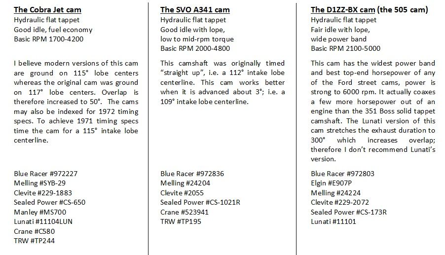
- Closing the intake valve too late causes low rpm reversion while lowering dynamic compression. Modern cam lobes have lobe intensity specs that are more aggressive (smaller numbers) than the factory cams, so closing the intake valve by 70° ABDC seems to be a reasonable limit. The Cobra Jet cam and the D1ZZ-BX cam both closed the intake valve at about 40° ABDC based on duration at 0.050", that's another calculation I make to check cams in these days of faster cam lobes.
Camshaft grinders are unwilling or incapable of grinding camshafts with LSA greater than 115°. In fact, camshaft grinders are even reluctant to grind cams with 115° LSA. The most “street-able” off-the-shelf aftermarket cams are ground with 112° to 114° LSA. Even when having a camshaft custom ground you’ll encounter less resistance from camshaft grinders if you specify 114° LSA instead of 115° LSA. For this reason, and this reason only, 114° is realistically the widest LSA we have to work with. Combining the capabilities of the 4V cylinder heads, camshaft timing within the limits I've recommended, and high-lift-rate camshaft lobes (max valve lift in the range of 0.550” to 0.600”, hydraulic intensity in the range of 50 to 62) imbues an engine with good drivability, a wide power band AND hard-hitting performance. This I guarantee.
One GOOD off the shelf cam sticks out in my mind, the Crane Cams HR-216 hydraulic roller cam.
If you would like my assistance in specifying a custom cam for your 351C street or sports car application you are welcome to contact me privately, via one of two methods:
(1) Via a "private message" using the messaging capability of these forums. i.e you'll have to join the forums.
(2) Via an email sent to "info at Pantera International dot org".
If you contact me via one of those two methods, I will gladly assist you.
I have assisted many people over the decades (since the 1970s), and I will gladly assist you as well. But frankly, I would prefer if you asked for guidance at the beginning of your project, rather than just asking for help with the camshaft.
Pay attention to this: I offer assistance to folks who own vehicles powered by the 351C who wish for nothing else beyond achieving the best performance the factory 351C castings had to offer.
I don't offer help choosing off the shelf cams, in terms of camshafts my specialty is penning custom cams for high performance street engines which perform better as street cams than any mass-produced cam available off-the-shelf. I don't offer help designing drag racing cams, I don't offer help designing cams for high output custom engines (beyond 450 bhp). Custom engines are those equipped with alloy heads and/or stroker crankshafts.
CAMSHAFT TIMING SETS
A high quality steel timing set having a 9 keyway crankshaft sprocket and a camshaft sprocket with steel teeth (as opposed to plastic teeth) is the durable and practical choice. The multi-index crankshaft sprocket is an invaluable aid in properly timing a camshaft. Some choices include: Roll Master #CS 3091, Ford Racing Performance Parts #M-6268-A351, or Cloyes #9-3621X9.
LUBRICATION
Unless your 351C has been specifically set-up to operate with low viscosity 0W or 5W synthetic motor oil, the recommended oil viscosity for Cleveland Fords (built to standard 351C specification) is 20W50, 15W40, 10W40 or 10W30.
Motor oil providing a high level of wear protection is required to prevent premature failure of flat tappet camshaft lobes, flat tappet lifter faces AND distributor drive gears. It is important to emphasize that installing a roller cam does not eliminate the need for motor oil providing a high level of wear protection; it is still needed for the distributor drive gear! The traditional recommendation has been to select oil containing more than 1200 ppm of both zinc and phosphorous, the constituents which make the anti-wear agent known as ZDDP. However a high level of ZDDP does not guarantee a motor oil provides a high level of wear protection. ZDDP oil additives do not help either; they reduce the wear protection properties of motor oil! My recommendation is 10W30 Valvoline VR1 Racing Oil, either petroleum based (silver bottle) or synthetic (black bottle); it is reasonably priced, it is readily available and it provides a high level of wear protection.
VALVE TRAIN PERFORMANCE, WEIGHT, AND LONGEVITY
The dynamic goal in a high performance valve train is to remain in control of the valves up to the motors rev limit. Parts should be rigid enough so that their shape does not distort. Parts should also be light, they should remain in contact with one another, and they should follow the cam's motion precisely. There should be no unwanted motion in the valve train; such as wiggling, bouncing, surging, floating or flexing. The properties of the moving valve train parts that work against the performance enthusiast are inertia, energy storage, flex, oscillation, resonance ... AND cheaply made parts!
Valve train wear increases proportionally to increases in valve spring force. Increasing valve spring force shall also lower the rpm at which hydraulic tappets collapse. We can’t increase a street motor’s valve spring force indefinitely if we expect the valve train to operate for many miles without needing rebuilding, or if we wish to avoid hydraulic tappet collapse. If we install the strongest valve springs recommended for street applications (such as those I’ve recommended below) and find valve float OR hydraulic tappet collapse occurring at a lower rpm than we prefer, or find the motor suffers from valve train instability issues, the next course of action may be to lighten the valve train.
Weight removed from a valve or valve spring retainer is more effective than weight removed from a push rod or tappet, due to the multiplication of movement built into the rocker arm. With a 351C, which has a 1.73:1 rocker arm ratio, any weight removed from a valve or valve spring retainer is 1.73 times more effective than the same amount of weight removed from a push rod or tappet. The most important characteristic for a push rod or tappet is to be completely rigid, free from flex and distortion. Since it is less effective to lighten these parts anyway, the prevalent reasoning is to choose these parts based on strength, and to focus on lightening the valve train via the valves and retainers, where each gram of weight reduction is more effective. A rule of thumb used in the hot rod industry says reducing the weight of these components by 1 gram will raise a motors rev limit by 25 rpm.
Manley’s stainless steel "severe duty" 4V intake valve weighs 139 grams. Manley’s stainless steel "severe duty" 4V exhaust valve weighs 108 grams. The intake valves each weigh 31 grams more than the exhaust valves! There is a lot of performance to be gained by replacement of the "severe duty" intake valves with lighter valves such as Manley's "Race Master" intake valves (129 grams). Reducing the weight of the intake valves by 10 grams raises the rev limit by 250 rpm. Adding titanium valve spring retainers for the intake valve springs is a moderately priced method for removing a few extra grams of weight, and it is complimentary to the use of light weight intake valves.
Accelerated valve seat wear and valve stem or valve guide galling are problems encountered by some racing engines employing titanium valves, however keep in mind that race engines employ very high lift rate camshaft lobes and very high valve spring forces. Race engine builders are also tempted to set the valve seats thin in order to improve air flow. Regardless of how many beat up titanium valves a race mechanic has in his tool box, the lower lift rate camshaft lobes, lower spring forces and wider valve seats utilized in high performance street motors are an ideal application for titanium valves, if they are needed and/or within the budget. Whereas Manley's Race Master valve will raise the rev limit by 250 rpm, a Manley titanium intake valve would raise the rev limit by 775 rpm!
REPLACEMENT VALVES
There are not one but two reasons for replacing the OEM factory valves. (1) The factory valves have brittle heads; they sometimes crack near where the heads are induction welded to the stems. Cracking leads to the valve head falling off the valve stem while the motor is running, and destructive damage occurs to the motor. (2) The valve springs are retained by loose fitting multi-groove valve spring locks which are not fit for performance usage, i.e. higher than stock valve spring forces and high engine speeds. This is substantiated by Ford’s choice to install single groove style valves in the Boss 351. People have been replacing the factory Cleveland valves with Manley severe duty stainless steel valves for decades, since the motors were new. They are a high quality, time proven substitution. Manley Performance is located in Lakewood New Jersey; their telephone number is (732)905-3366.
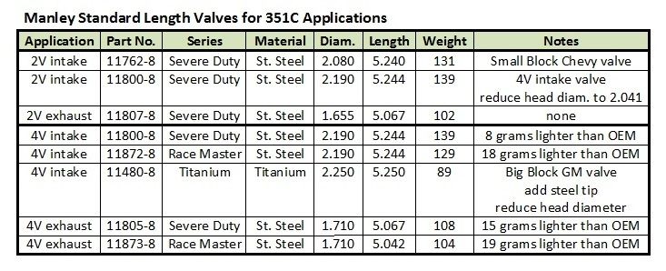
Whatever brand of valves you choose, it is imperative the stainless steel or titanium valves you purchase have hardened steel tips. Cast iron or beryllium-copper valve seats are complimentary to stainless steel or titanium valves. To prevent rapid wear of stainless steel or titanium valves in the valve seat area the cylinder head’s intake seat width should not be less than 0.060” and the exhaust seat width should not be less than 0.080”; seat run-out should be 0.001” or less. Equip the cylinder heads with silicon-bronze valve guides to best compliment stainless steel or titanium valve stems. The valve stem to guide clearance should be set at 0.0010" to 0.0020" for the intake valves and set at 0.0015" to 0.0025" for the exhaust valves. Utilize spring loaded elastomer valve stem seals such as Ford Racing Performance Parts #M-6571-A50 or Manley Performance #24045-8; installation of this type of seal requires machining of the top of the valve guide to 0.530” diameter.
continued in the next post