.
Rebuild - Freshen Up - Overhaul
Assuming it is in sound working order, the limits of a 351C with factory machine tolerances, factory cast pistons, factory connecting rods, factory balanced reciprocating assembly, and hydraulic tappet valve train are 425 horsepower, 6500 rpm, and 8.0:1 dynamic compression or 10.5:1 static compression (whichever comes first). At that point the cast pistons, the engine's thin cylinder walls, the connecting rod fasteners, and the factory valve train are highly stressed. The factory fuel pump and the factory clutch are also pushed to their limits.
425 naturally aspirated horsepower is on par with the top pre-emissions (pre-1968) production street engines of the muscle car era: Ford's 8-bbl 427 (R code), Chrysler's 8-bbl 426 Hemi, Chevy's 4-bbl 396 (L78), and Chevy's 4-bbl 427 (L72) were all rated 425 horsepower. Pontiac's 6-bbl 421 Super Duty was the lowest rated at merely 376 horsepower, and Chevy's 6 bbl 427 (L71) was the highest rated at 435 horsepower.
The folks at De Tomaso built Pantera race engines using production castings. These were race prepped engines with forged pistons, chromoly rods, internally balanced cranks, and solid tappet cams. To survive a season of European endurance racing the engines were limited to 440 horsepower, 7000 rpm, and 10.5:1 static compression. Their strategy was not to make as much horsepower as possible but to stay within the engine’s limitations for that application (European endurance racing). In ten years of racing, 1974 to 1984, Odoardo Govoni won 3 Italian championships and 1 European championship piloting the group 4 Pantera chassis # 2873.
To push an engine to its limits, or to maximize an engine's limits, it should be in sound working order. Its bearings, rings, and valves should be in good condition, its reciprocating assembly should be factory balanced or better, and it should be in a good state of tune. Thus a rebuild, overhaul, or "freshen-up" is usually in order. Typical of a rebuild, if pistons are needed they would be low cost OEM style cast replacements. Machine shop services would be relied upon only for cylinder head servicing and connecting rod servicing. Crankshaft journals and cylinder bores would be used "as-is" when possible; bearing journal reconditioning and cylinder boring services would only be enlisted when necessary.
An engine that is "merely" rebuilt or freshened-up shall not be as durable as it could be if it were race prepped or blue printed. Nothing is done to extend an engine's limits. There is nothing wrong with that. But, as a consequence, the as-built limitations suggested above remain the boundaries to work within.
Ten Emendations to Include in a Rebuild
The 351C has 3 recurrent issues which can be quite destructive:
(1) The heads of the factory valves break-off their valve stems from time to time and bang around inside the cylinders.
(2) The connecting rod bearings are under-lubricated which damages the bearings to the extent that hot oil pressure is impaired.
(3) The threads strip out of the connecting rod nuts, the big end caps come loose, and the connecting rods bang around within the cylinders.
Taking steps to prevent those issues from happening is logical, especially since two of the issues simply require the replacement of parts. The third requires the installation of bushings in the engine block and increasing bearing clearances. The steps for preventing all 3 issues should be taken when an opportunity (like a rebuild) arises to make them.
(4) An upgrade to a breakerless electronic ignition can be accomplished with Ford parts, with the exception of the wiring harness. Immediately noticeable upon installation of a breakerless ignition, the engine starts quicker, runs smoother, and has better low rpm power. Power actually improves at all engine speeds. The ignition is a significant improvement over any breaker point ignition, including a dual point ignition. There are no points to adjust, thus maintenance is reduced.
Those four improvements are appropriate for any and all 351C rebuilds. The remaining six emendations pertain to performance engines.
(5) An oil pump cannot provide an uninterrupted supply of oil to the engine unless its suction is constantly submerged in a bath of non-aerated oil. An inadequately designed oil pan can exacerbate the engine's lubrication problems mentioned above (issue #2). A high-capacity oil pan with baffles, hinged doors, a windage tray, and a scraper enables the lubrication system to better cope with the high G-Force capabilities (braking, cornering, acceleration) of the Pantera's chassis. Such an oil pan should have been standard equipment for the Pantera. De Tomaso equipped the GTS, GT5, and GT5-S Panteras with high-capacity oil pans and windage trays.
(6) A prerequisite to raising the compression ratio is a carburetor with a richer A/F ratio. Using an emissions-tuned carburetor with raised compression would result in knocking, pinging, and detonation. There are no factory carburetors with the proper calibration.
Besides being a prerequisite to raising compression there is also horsepower to be gained by replacing the 4300 series carburetors. The 1970 carburetors were down 3% (down 10 HP out of 310 potential HP), the 1971 carburetors were down 8% (down 25 HP out of 310 potential HP), the 1972 and 1973 carburetors were down 20% (down 70 HP out of 350 potential HP), and the 1974 carburetors were down 17% (down 61 HP out of 350 potential HP). De Tomaso equipped the GTS, GT5, and GT5-S Panteras with 650 cfm (non-emissions) Holley list R4777 carburetors.
Engines equipped with factory spread bore carburetors will need to replace the "spread bore" intake manifolds with dual plane manifolds designed for "square bore" carburetors.
(7) The 351C was a performance engine manufactured in an era of declining performance, and declining compression ratios. Improving (restoring) the 351C's performance has been a common theme since the engine was new. Raising the compression ratio improves the engine's dynamic performance (throttle response, acceleration, low rpm torque). This is the most important change to make for improved performance. Zero to sixty times improve by 2 to 3 seconds.
(8) The factory push rods were flimsy. Ford and other manufacturers designed them that way intentionally as a sort of mechanical rev limiter. To gain rpm at the upper end of the power band, and to extend the rev limit, stiffer push rods are needed.
(9) The connecting rod fasteners are the most stressed and most critical fasteners in the engine. If 350 horsepower was expected to be adequate the OEM fasteners would also be adequate. It is prudent however to improve the fasteners in preparation for increased output and increased rpm, even Ford installed chromoly connecting rod fasteners in the 351 Boss.
(10) Ford also installed a heavier, fully bonded damper on the 351 Boss. Since the damper is most likely overdue for replacement, it seems logical to purchase a damper similar to the 351 Boss damper for this or any "performance" application. The 351 Boss damper has not been available for decades, so we'll have to resort to an aftermarket damper of similar or better design. A good one will be suggested.
Factual Compression Ratio
There are two things to become accustomed to as you continue reading.
First, no auto manufacturer's sales department ever published dynamic compression ratios, although their engineering departments used dynamic compression ratio to determine what fuel octane an engine required.
Second, the static compression ratios being quoted are factual, real-world compression ratios; not the grossly exaggerated advertised compression ratios that US Ford published through 1971.
Most of the high compression engines of the 1960s operated on "premium" gasoline, that indicates their dynamic compression ratios were in the range of 7.0:1 to 8.0:1. Fuel rated "regular" was for engines having 7.0:1 dynamic compression or less. Fuel rated "super-premium" was for engines having dynamic compression greater than 8.0:1. Very few engines were ever designed for "super-premium" fuel. Ford specified premium fuel for the 1970 M code, 351-4V. The sales department's claim that it had 11:1 compression was never possible.
Mass produced engines are built with tolerances. The 1970 M code engine had between 9.30:1 and 10.02:1 static compression, 9.65:1 being the nominal value. The engine's dynamic compression was between 7.14:1 and 7.67:1, 7.40:1 being the nominal value.
How Much to Raise the Compression
Raising the compression of an engine improves its "dynamic performance" in terms of low-end torque, pep, acceleration and throttle response. As a consequence, having a strong performing engine is secondarily about how much horsepower the engine makes … it is primarily about how much compression it has.
Raising the compression of an engine improves performance so well that many enthusiasts assume it must significantly increase horsepower … but it doesn't. For example, assuming an engine produces 350 horsepower:
• Raising the compression from 8.0:1 to 10.0:1 increases output by 11.0 HP.
• Raising the compression from 8.5:1 to 10.0:1 increases output by 7.4 HP.
Raising compression is also a condition of diminishing returns:
• Raising the compression from 8.0:1 to 9.0:1 increases output by 6.6 HP.
• Raising the compression from 9.0:1 to 10.0:1 increases output by 4.5 HP.
• Raising the compression from 10.0:1 to 11.0:1 increases output by 3.1 HP.
• Raising the compression from 11.0:1 to 12.0:1 increases output by 2.3 HP.
There are limits to how much the compression can be raised. The 351C was originally designed to operate on premium fuel. That is 91 octane US/Canadian fuel (R+M/2) or 95 octane international fuel (RON). Thus, it was intended to have dynamic compression no greater than 8.0:1. The two 351C factory engines with the highest compression, the 1970 M code and the 1971 R code (351 Boss), had in fact 7.40:1 dynamic compression and 7.43:1 dynamic compression, respectively (nominal values).
The Cleveland is infamous for having cylinder walls designed as thin as possible; the engineers didn't leave any "wiggle room". The Cleveland cylinder wall thickness specification was 0.160 inch ± 0.030 inch. The cylinder walls could have been as thin as 0.130 inch in spots, right off the assembly line. That is literally half as thick as they should have been. This limits how high the compression ratio can be safely raised without incurring cylinder wall damage. That limit is traditionally 10.5:1 static compression.
In regard to compression, the Cleveland's upper limit is best stated as 8.0:1 dynamic compression (based on the fuel) or 10.5:1 static compression (based on the cylinder walls), whichever comes first. Those limits, as they impact street operation on premium fuel, employing short duration street cams, aren't bad at all, they pose no handicap to performance.
With high performance (Cobra Jet) street engines, short intake duration and early (advanced) cam timing combine to close the intake valves early, commonly between 66° and 72° ABDC. A static compression of 10:1 produces dynamic compression ratios between 7.92:1 and 7.53:1, respectively. However, 10:1 compression is not exactly 10:1 compression. It varies based on the diameter (over-bore) of the cylinders. 10:1 static compression can actually be as low as 9.80:1. A "worst-case" scenario combining 9.80:1 static compression with a 72° IVC produces a dynamic compression ratio of 7.40:1. That's still OK.
How Best to Raise the Compression
To raise the compression of a 351C ALL Cleveland cylinder heads (excepting the Australian 302C heads) need some amount of milling to reduce their chamber volumes.
Raising the engine's compression with open chamber heads can be accomplished in two ways. The first way requires zero-decking the block (lower the decks by 0.015-inch, raise the compression height by 0.020-inch). The second way employs pop-up dome pistons. Either method requires an expensive set of pistons and re-balancing the reciprocating assembly.
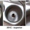
BUT raising compression with quench chamber heads doesn't require milling the block, an expensive set of pistons, or re-balancing the reciprocating assembly. If dished pistons need to be replaced, an inexpensive set of cast flat tops which weigh the same as the dished pistons (about 616 grams) is all that is needed. The simplicity and lower expense of raising compression with quench chamber heads makes them the best method for raising compression during a simple rebuild.
Ford produced the following quench chamber heads.
• US Ford 1970 M code, D0AE castings, 4V ports, 62.8 cc chambers
• US Ford, 1971 M code, D1AE castings, 4V ports, 66.1 cc chambers
• Australian Ford '72–'75 Y code (302C), 2V ports, 57.9 cc chambers
• Australian Ford '76–'84 P code (302C), 2V ports, 57.9 cc chambers?
• US Ford Motorsport 1986, p.n. M-6049-C351, 2V ports, 62.0 cc chambers
To make 10:1 compression with any of the US manufactured quench chamber cylinder heads start by milling the heads to achieve 61 cc chamber volume. Milling quench chamber heads 0.006-inch reduces chamber volume by 1 cc. D0AE heads require nominally 0.010-inch milling, D1AE heads require nominally 0.030-inch milling. Employ production cast flat top pistons, and employ 0.038-inch head gaskets. If over-bore pistons with full 1.650 inch compression height and only 3 cc dome volume are used then 0.047-inch head gaskets would be necessary. This is unlikely if off-the-shelf cast pistons are employed.
The Australian 302C heads have smaller combustion chambers. To make 10:1 compression they do not require milling, use them as is (58 cc chamber volume). Employ production cast dish top pistons, dish top pistons have 5 cc more dome volume than flat top pistons. Employ 0.038-inch head gaskets. If the heads are milled then 0.047-inch head gaskets would be necessary.
The following 351 Cleveland specific rebuild information is presented in the format of a "budget conscious" home mechanic style rebuild.
Cylinder Heads
It is assumed that 4V quench chamber (M code) heads shall be utilized. If they are not on hand, acquire a set.
Recurring Problem # 1
The 351C has an issue with the valve heads of the factory valves breaking-off their valve stems from time to time, they bang around inside the cylinder and wreak havoc on the engine. To prevent this from happening, and for peace of mind, the factory valves must be replaced.
The factory valves were two piece valves; the stems were welded to the valve heads. Most valves are manufactured that way. There are people who have been led to believe that in order to be reliable replacement valves "must" be of one piece construction. However, the two piece construction of the factory valves had nothing to do with their failure. When the valve heads crack and break off the stems, this happens below where they are welded together. The problem with the Ford valves was that the valve heads were brittle.
D0AE, D1AE and D1ZE 4V heads are equipped with the large 2.19/1.71 valves. All other Cleveland heads, including the D3ZE 4V heads, are equipped with 2.041/1.655 valves.
Replacement valves can be whatever type or brand are preferred, so long as they are not another set of factory valves! A set of steel valves from Melling or Sealed Power would be satisfactory. For a performance oriented engine stainless steel valves make a good choice because they are lighter weight, swirl polished, and have single groove style stems. Stainless steel valves (and titanium valves) are made of softer materials, the valves tips should be equipped with steel inserts. The valves sold by Manley Performance are excellent suggestions … but there are lower priced alternatives.
The first machine shop task is servicing the M code heads. The heads may be needed once servicing the block is underway.
Machine Shop Task #1:
Servicing the heads is a five-part task: (A) hot tank, (B) check for leaks, (C) mill the heads, (D) install bronze valve guides, and (E) service the valve seats.
The heads should be milled to achieve 61 cc chamber volume; mill D0AE castings nominally 0.010 inch, mill D1AE castings nominally 0.030 inch.
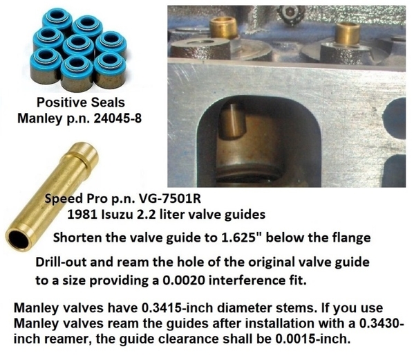
The bronze valve guides should be the type which are flanged at the top for "positive seals". The old cast iron guides sticking up above the spring pedestals are eliminated. The cast-in guides inside the valve pockets can be eliminated too, that is a matter of personal preference. Ford's endurance racing specs for valve stem to valve guide clearances are:
• Intake valves: 0.0007 inch to 0.0018 inch (0.0012-inch nominal)
• Exhaust valves: 0.0011 inch to 0.0022 inch (0.0016-inch nominal)
Reaming all the valve guides for 0.0014-inch clearance is one strategy. The production specs were nominally 0.0018-inch for the intake valves and 0.0023-inch for the exhaust valves.
If the heads require new valve seats then stainless steel valves (and titanium valves), which are made of softer materials, should be complemented with iron or beryllium copper ($$$) valve seat inserts. Hardened steel or stellite inserts should be used with steel valves.
The Cleveland ports are well designed and perform competently "as-is". With a little "clean-up" and a "proper" three angle valve job air flow can be improved by about 15%. But, the port's performance cannot be improved by modification, only undermined. Thus as little material as possible should be removed.
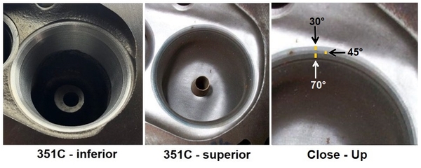
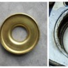
Three angle valve seats should appear as three thin - concentric - rings, such as the cuts in the close-up picture. Take note that the valve pocket in the center picture has been hand smoothed, not cut with a machine. Cutting was restricted to the valve seats. Very little material has been removed.
The valve pocket has very specific dimensions and an intentional shape (profile). There is a venturi (throat) above the valve seats. The valve pocket has "some" cutting above the valve seat performed by the factory. That cutting roughly defines the pocket's throat, but it can use some improvement. The 4V intake valve pocket's throat (1.74-inch diameter) should not be enlarged or eliminated. The valve pocket cannot be serviced or improved with a valve seat cutting machine. Any wide cut, tapered like a funnel or straight walled like a barrel, RUINS the valve pocket and undermines port performance. The head in the left hand picture above appears to have been additionally cut, beyond the factory machining. If so, then it has been butchered. That head would honestly perform better if the valves had just been lapped-in.
Choose a machinist who will restrict his valve seat cutting to three thin - concentric - rings.
The original factory machining left ridges and sharp edges around the valve seats in the combustion chamber and in the valve pocket. For the best air flow a little bit of preliminary hand blending is helpful to knock down and blend the ridges left by machining, and a little emery cloth work is sufficient to round-off the sharp edge in the throat. The backside of the valve pocket, opposite the short turn radius, can use a little additional blending above the throat, to better define the venturi.
The valve seat angle should be cut at 45°.
The valve seat should be blended into the combustion chambers with a 30° cut. The peripheral size of the 30° cut is limited by the adjacent valve. The inner diameter of the 30° cut sets the peripheral size of the valve seat, which should be near the outer edge of the valve. This cut must negotiate those limits, thus it is necessarily narrow, but should be about 1/16-inch wide.
The valve seat should be blended into the valve pocket with a 60° or 70° cut. Ford literature recommended both. 60° may be a little more resistant to human error. The width of the 60°/70° cut should be the same around the entire circumference, about 1/8 inch. The periphery of this cut sets the width of the valve seat. To improve air flow without undermining durability the width of the intake seat should be 0.060-inch to 0.070-inch, or about 1/16 inch. Much narrower than in the left hand picture above. To provide adequate heat transfer the width of the exhaust seat should be 0.080-inch to 0.090-inch, or a bit more than 5/64-inch but a bit less than 3/32-inch.
Finally, valve seat run-out should be 0.0010 inch or less. The run-out spec is important for durability.
Engine Block
Degrease the block. Don't neglect the cam bearing oil passages. They always get plugged with sludge.
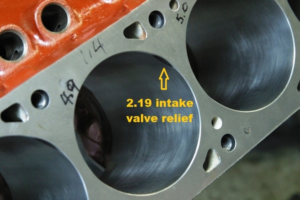
The M code heads were equipped with 2.19-inch intake valves. If the engine's block doesn't have reliefs ground into the tops of the cylinders for 2.19" intake valve clearance, those reliefs will have to be ground. This is when the serviced heads are needed. If the cylinders are going to be bored, this should be accomplished before boring them.
Assemble one head using valve train checking springs. Use that head on both banks to establish where to grind the 2.19-inch valve reliefs, and to check for clearance afterwards. Snugly bolt the head to the engine block with dowels in place and flip the block upside down to mark where to grind.
> A Decision must be made whether or not the cylinders should be bored. The degree of scoring is one factor to consider, cylinder bore taper is another. The factory wear limits are:
• Maximum cylinder bore out of round: 0.005-inch
• Maximum cylinder bore taper: 0.010-inch
• Piston to cylinder bore clearance: 0.0014-inch to 0.0022-inch
That much taper is unlikely; but it needs to be measured to be sure. Severely tapered cylinders would need to be bored and honed for oversize pistons. If the cylinders must be bored DO NOT jump immediately to a 4.030-inch over-bore. Over-bores should be kept to a minimum due to the thin cylinder walls; Clevelands can usually be cleaned-up with merely 4.010-inch over-bores.
If the cylinders are not being bored, then ream the ridges at the top of the cylinders and hone or deglaze the cylinder walls. Clean the cylinder walls well afterwards.
If the engine has dish top pistons, or if the existing pistons are badly scored, substitute them with a new set of factory style cast flat top pistons (1.650-inch compression height). The factory pistons have steel struts in the skirts and are a bit heavy. The replacement cast pistons should be designed the same and should weigh the same as the OEM pistons (about 616 grams), thus the crank won't need rebalancing. Seek out pistons manufactured in North America (Silv-O-Lite, Sealed Power, Clevite, etc.).
Replacement pistons for standard 4.000-inch bores should have 1.650 inch compression height and 3 cc dome volume (valve reliefs). For over-size bores you should expect them to have less compression height OR increased dome volume (slightly dished domes), but not both. These are the piston manufacturers' methods to prevent an increase in compression resulting from an over-bore. The following piston dimensions maintain the compression ratio for various bores:
• Std. 4.000 bore: 1.650-inch compression height and 3.0 cc dome volume
• 4.010 over-bore: 1.648-inch compression height or 3.4 cc dome volume
• 4.020 over-bore: 1.646-inch compression height or 3.8 cc dome volume
• 4.030 over-bore: 1.644-inch compression height or 4.2 cc dome volume
• 4.040 over-bore: 1.642-inch compression height or 4.6 cc dome volume
Machine Shop Task #2:
Replacing the pistons will require the help of a machine shop to remove and re-install the pressed pins. The spec for the minimum amount of force to remove the pressed pins is 1800 lbs. If the pins are removed with less force than that there is a problem. Pins are normally installed by preheating the small end of the connecting rod.
If the pistons aren't being replaced, clean the ring grooves of the existing pistons. Those pistons need to go back into the bores they came out of, clocked the same way they came out.
If the cam bearings are being replaced, installation of the no. 1 cam bearing requires special attention. If the bearing is not installed properly then the camshaft thrust plate, the timing gear, and the fuel pump eccentric will be unlubricated. The slot in the #1 cam bearing must be oriented to connect the cam bearing oil supply passage and the thrust plate oil passage. Once the slot in the bearing is aligned to connect the two oil passages the bearing must be installed to a depth of 0.003 inch to 0.005 inch within its bore, beyond flush with the front machined surface, as measured with a straight edge and feeler gages.
This is a good time to point out that the slots or holes in the camshaft timing sprocket allow spray lubrication from the thrust plate oil passage, located behind the cam sprocket, to reach the fuel pump eccentric on the front of the cam sprocket. Some camshaft timing sprockets lack holes or slots, don't purchase one like that.
Recurring Problem # 2
The 351C has an issue with under-lubrication of the connecting rod bearings, and low hot oil pressure (should be 50 to 70 psi at 2000 rpm). As the bearing wear increases, the hot oil pressure decreases … and so do the engine's durability limits. The engine's limits (425 horsepower, 6500 rpm) depend upon the engine's bearings being in good condition. This issue shall be dealt with in this section and the next three sections.
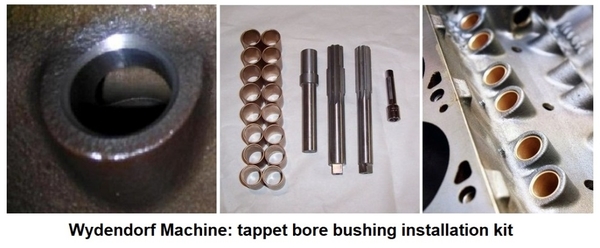
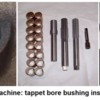
Install tappet bore bushings in all 16 tappet bores. Suggested orifice size is 1/16th inch (0.062-inch). This can be done at home, the kit is $400. Clean the block again, after enlarging the tappet bores, but before installing the bushings … and then clean it a third time after the bushings are reamed to size. It must be assumed every particle of metal left behind will become a problem.
DO NOT install a restrictor in the oil passage supplying the left-hand bank of tappets. The single restrictor has led to the random collapse of hydraulic tappets on the left-hand side of the engine. It's only needed when merely 8 tappet bore bushings are installed (in the right hand tappet bores), and it is only viable with solid tappets. It's not needed at all when bushings are installed in all 16 tappet bores.
The benefits of installing 16 tappet bore bushings include:
• Hot oil pressure at 2000 rpm shall be within spec (50 to 70 psi).
• Minimizes the amount of oil loss due to leakage at all 16 tappet bores.
• Maximizes the amount of oil supplied to the main bearings.
• Prioritizes the lubrication of the main bearings.
• Isolates the oil passages from tappet motion (cavitation).
• Prevents the random collapse of left-hand hydraulic tappets.
• Resolves tappet compatibility issues on both sides of the engine.
• Prevents an excessive amount of oil flowing to any part of the valve train.
• Equalizes the amount of oil metered to all 16 rocker arm/valve/valve spring assemblies.
Crankshaft
"Carefully" and "lightly" chamfer the oil holes in the crank, clean the passages afterwards.
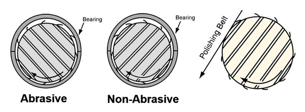
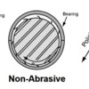
Polishing the journals of a nodular iron crank in the wrong direction shall raise microscopic burrs which make the journals abrasive, leading to bearing damage. So don't polish the crank unless which direction to polish the crank is understood. The correct direction will cause the burrs to lay-down as the crankshaft rotates.
> A Decision must be made whether or not the crankshaft journals should be reconditioned. The degree of scoring is one factor to consider. Here are the factory specs:
• Main bearing journal OD = 2.7484-inch to 2.7492-inch (2.7488-inch nominal)
• Main bearing journal maximum run-out = 0.004-inch
• Main bearing journal maximum out-of-round = 0.0004-inch
• Main bearing journal maximum taper = 0.0003-inch per inch
• Rod bearing journal OD = 2.3103-inch to 2.3111-inch (2.3107-inch nominal)
• Rod bearing journal maximum out-of-round = 0.0004- inch
• Rod bearing journal maximum taper = 0.0004-inch per inch
New bearings should be heavy duty bearings (Clevite tri-metal or similar). Heavy duty rod bearings are not damaged as badly by under-lubrication as standard babbitt style bearings are. They will also stand-up better to the less than perfect journal surfaces if the crankshaft is not reconditioned.
The main bearings should be fully grooved. Fully grooved main bearings were once standard equipment in heavy duty bearing sets; they more than double the amount of oil supplied to the connecting rod bearings. The 351C has NEVER suffered any problems stemming from the use of fully grooved main bearings, only benefits. Considering the Cleveland's problems with under-lubrication of the rod bearings, fully grooved main bearings should be considered essential.
If the crank is being reconditioned by a machinist, specify 0.0025-inch to 0.0030-inch rod & main clearances. If it is not being reconditioned then achieve those clearances by using oversize bearings. Those clearance specs are Ford's endurance racing specs. Ford's production specifications were too tight:
Factory Main Bearing Clearance Spec
• Desirable spec = 0.0010 inch to 0.0015 inch
• Allowable spec = 0.0011 inch to 0.0028 inch
Factory Connecting Rod Bearing Clearance Spec
• Desirable spec = 0.0010 inch to 0.0015 inch
• Allowable spec = 0.0011 inch to 0.0026 inch
If fully grooved mains can't be found in oversized kits, use the grooved upper shells from two standard (1/2 groove) oversized bearing kits.
Install the main bearings, the crankshaft, and the main bearing caps. Torque the main bearing cap inner bolts (1/2-inch) to 95-105 ft./lbs. Torque the main bearing cap outer bolts (3/8-inch) to 35-45 ft./lbs (IF the caps have outer bolts).
Make sure the crank can be rotated by hand in the bearings. Then measure the crankshaft’s end play. If the end play exceeds 0.010-inch the excess end play can be corrected using a no. 3 main bearing with thicker thrust faces, known as a “cranksaver” bearing.
Checking the flywheel is another task to perform while the crankshaft can be rotated by hand. If the flywheel’s assembled clutch face run-out is 0.010 inch or less, if it has the typical grooves and ridges but can be cleaned up by removal of no more than 0.045-inch material, then a simple resurfacing may suffice. However, if the flywheel shows signs of stress cracking or heat checking, if it would require the removal of more than 0.045-inch material to clean it up, if it is warped or has excessive clutch face run-out, then the flywheel should be replaced. The flywheel bolts are torqued to 75-85 ft./lbs.
Once all of that is checked and any problems are resolved, disassemble the main bearing caps, remove the crank, and install the rear main seal. If you're replacing the rope style rear crank seal with a split rubber seal, pull the little pointy pin from the seal groove in the #5 bearing cap. Put a dab of sealant in the hole the pin left behind.
The main bearings, the crankshaft, and the main bearing caps can be reassembled for the final time.
Motor Oil
“Low viscosity” motor oil promotes the flow of oil through oil passages, around the corners of intersecting passages, and through bearing clearances. There are other considerations however:
• There is concern that if the oil viscosity is too low the grooves in the lower bearing shells of "fully grooved" main bearings may act like the rain grooves of tire treads and channel oil away from the bearing clearances.
• The amount of oil flowing into the rod bearings increases as viscosity decreases, but the persistence of the oil wedge improves as viscosity increases.
• 1970 mass-production machine tolerances (concentricity, roundness, taper) are not good enough for ultra-low viscosity motor oil.
Thus, there is a balancing act involved with the selection of oil viscosity; low viscosity motor oils are advantageous, so long as the viscosity is not too low. To support the goal of maximizing the lubrication of the rod bearings low viscosity motor oil rated 10W30, 10W40, or 15W40 should be used. But, to prevent any of the expressed problems from arising oil viscosity lower than 10W30 is not recommended.
Valvoline VR1 10W30 synthetic oil is an excellent choice for an older engine like the 351C, especially one equipped with a flat tappet camshaft.
Connecting Rods
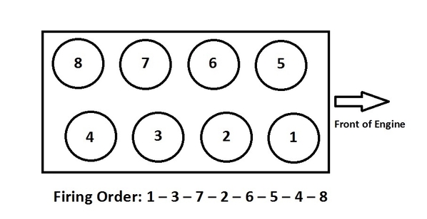
Install the piston and rod assemblies, less rings, in the appropriate bores and fasten them with new bearings to the rod journals. Its important to maintain the rod pairings for each connecting rod journal. Rods sharing the same journal are 1&5, 2&6, 3&7, and 4&8. Torque the rod nuts to 45 ft./lbs.
Connecting rod "side-clearance" is the source of "oil splash". Oil splash lubricates the thrust walls of cylinder bores, it also lubricates cam lobes and tappets. Most relevant to the subject of 351C lubrication, tight side-clearances will inhibit the flow of oil through the rod bearings.
The side-clearances between paired rods should be 0.018-inch to 0.022-inch as per Ford's endurance racing spec. The production spec was 0.010-inch to 0.020-inch with a wear limit of 0.023-inch. Measure the rod side-clearances, see how close they are to 0.018-inch before you decide how to proceed. I'd reluctantly let 0.016-inch ride, but no less.
One way to measure the side-clearances is with a dial indicator, tapping the rods lightly to be certain they are fully to one side and then the other. Another way is to spread the rods apart, then measure the gap with a feeler gauge. If the side-clearance is insufficient the inside mating faces of the rods (not the fillet sides) must be cut with a surface grinder. Half of the desired increase in side-clearance should be taken off each mating face of the pair.
Machine Shop Task #3:
Take the rods to a machinist in pairs (rods from the same journal), and have metal removed from the mating faces of each pair based on the side clearance measurements.
Recurring Problem # 3
While on the subject of the connecting rods, the 351C has an issue with threads stripped out of the connecting rod nuts. The stripped-out nut allows the big end cap to come loose, the connecting rod bangs around within the cylinder, and severe engine damage occurs. To prevent this from happening the connecting rod nuts should be replaced with the ARP # 300-8381 nuts.
However, if the rods are being taken to a machinist, consider going one step further and install heavy duty rod bolts, then have the machinist resize the big ends while he has the rods. The additional expense is minimal. Whereas the factory rod bolts have a tensile strength of 150,000 psi and are rated for 45 ft./lbs torque, chrome moly rod bolts have a tensile strength of 180,000 psi and are rated for 50 ft./lbs torque.
Note: If the rod bolts are replaced the big-ends of the connecting rods MUST be resized.
ARP sells two chrome moly rod bolt kits: kit # 154-6003 (knurled shanks) and kit # 154-6403 (wave-loc shanks). For the ultimate in strength and clamping force another ARP “wave-loc” rod bolt kit, # 254-6403, is manufactured using their proprietary ARP2000 metal. Those rod bolts have a tensile strength of 220,000 psi and are rated for 55 ft./lbs torque. That one is a bit more expensive.
Machine Shop Task #4:
If the rod bolts are replaced have a machinist resize the connecting rod big ends. The Connecting rod big-end ID spec is 2.4361-inch to 2.4369-inch. Ask the machinist to aim for the minimum spec.
Now that the pistons and rods are done going back and forth to the machinist hand fit a new set of rings to each bore, install them on the proper pistons, then install the piston/rod assemblies in their proper bores and fasten them to their journals. The amount of torque (45, 50, or 55 ft./lbs) varies depending upon which rod bolts are being used, as previously discussed .
Getting all the rings fitted, all the pistons back into the block, and all the rods fastened to the crank is a milestone; light can seen at the end of the tunnel.
Ignition - Distributor
The next step is to prepare the distributor.
Install a breakerless electronic ignition, to avoid aftermarket parts Ford's Duraspark I or Duraspark II ignitions are suggested. Set the ignition for 16° to 18° static advance, and 20° centrifugal advance spanning 1800 rpm. The curve should start at 1000 to 1200 rpm and be "all-in" by 2800 to 3000 rpm.
20° centrifugal advance requires a 10L sleeve & plate assembly, or a sleeve & plate assembly with an 0.410 inch slot width.
That timing protocol (36° to 38° total advance) applies only to factory iron heads and flat top or dished top pistons. Pop-up dome pistons require more total advance, "Yates" (aka high swirl) combustion chambers require less total advance.
Increasing static advance improves an engine's low rpm pep. However, increasing static advance also makes an engine more and more difficult to crank during hot starts. Limiting static advance to 16° to 18° prevents the cranking effort from exceeding the torque of the starter motor.
Connect the vacuum advance to "ported" vacuum. Capping-off the vacuum retard connection inhibits operation of the distributor's vacuum mechanism, so leave it open to atmosphere.
If a Duraspark distributor is already in use, the centrifugal advance mechanism in Ford distributors should be serviced about every 50,000 miles.
Distributor gears may require replacement due to wear or camshaft replacement. The OEM gear was iron, whereas cams ground on steel cores require steel distributor gears.
Checking the distributor's end play and drive gear placement is most important whenever the distributor or distributor gear are replaced.
• Verify that distributor shaft end play is between 0.024-inch to 0.035-inch.
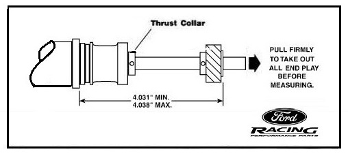
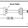
• Verify that the distance from the bottom of the distributor housing mounting flange to the bottom of the distributor gear is 4.031-inch to 4.038-inch when the distributor shaft is pulled away from the housing.
There is also an empirical method for testing the positioning of the distributor gear on the distributor shaft. This check must be performed prior to installation of the camshaft.
• Insert the distributor in the block.
• With the distributor housing fully seated against the block, verify that the distributor gear can be lifted off the support within the block at least 0.005”.
• Next pull the distributor gear downward and hold it firmly against the support within the block. Pull up on the distributor housing and verify you can lift it from the fully seated position at least 0.005”.
This procedure verifies the distributor gear is not being jammed downward against the support in the block and it is not being prevented from contacting the support in the block either.
If the position of the distributor gear must be moved, drill the new hole 90° offset from the existing hole. The holes are 0.125” (1/8”) ID. The distributor gear should fit the distributor shaft very tightly, and should require a press to install it or remove it.
Set the distributor aside for now.
Valve Train Inspection
Specialized tools and parts are required to perform these inspections. A set of 8 valve train checking springs, a pair of adjustable (measuring) push rods, a spare head gasket identical to the gaskets that shall be used for final assembly, a pair of spare tappets identical to the tappets being installed, a degree wheel, a dial indicator with a magnetic or clamping stand, and calipers capable of measuring at least 9 inches.
Rocker Arm Geometry
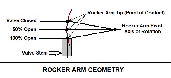
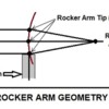
The goal in setting rocker arm geometry is to minimize valve guide wear. Although the rocker arm's tip travels in an arc, it's motion should be most linear in relation to the valve stem’s axis where it contacts the valve tip. Optimized geometry minimizes side thrust on the valve stem which in turn minimizes valve guide wear.
Three conditions are indicative of optimized rocker arm geometry:
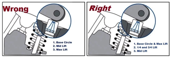
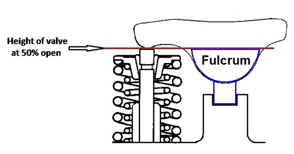
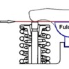
• An imaginary line drawn through the rocker arm's axis and across the valve tip is perpendicular to the valve stem’s axis when the valve is 50% open.
• The rocker arm's overall contact patch on the valve tip is thinnest when geometry is optimum.
• The rocker arm's point of contact on the valve tip is furthest from the fulcrum when the valve is 50% open.
Assuming the engine is equipped with factory rocker arms, the rocker arm geometry "should not" need to be checked if a factory cam is being utilized. If an aftermarket camshaft (higher lift) is being installed, then rocker arm geometry should at least be given a cursory inspection.
The Cleveland rocker arms are rigidly mounted on the cylinder heads; rigidly mounted rocker arms are also described as pedestal mount, saddle mount, or bolt down rocker arms. Rocker arm geometry can be checked and adjusted with the heads on the work bench; geometry is independent of push rod length. Rocker arm geometry is adjusted by raising or lowering the fulcrum height (aka stand, pedestal, or saddle height).
The heads will need to be fitted with valve train checking springs.
Theoretically, the fulcrum's "stand" should be in the middle of the rocker arm slot when the valve is 50% open. Also, an imaginary line drawn across the top of the fulcrum and across the tip of the valve should be perpendicular to the valve stem’s axis when the valve is 50% open.
If nothing else:
• Verify that the fulcrum stands shall not bottom-out in the rocker arm slots at max lift.
• Verify that there are no push rod interference issues at or near max lift.
• Verify that there are no interference issues with the valve spring retainer when the valve is closed.
If adjustments are to be made to the fulcrum height, the same adjustments "should" be made for all 16 rocker arms in order to maintain the consistency of push rod length and tappet pre-load (assuming there even is consistency of push rod length and tappet pre-load). There is always the possibility that each head may be a little different.
If rocker arm geometry is going to be adjusted, it should be adjusted before establishing push rod length.
Camshaft Installation & Timing
Install a new replacement Q code (Cobra Jet) camshaft, or an aftermarket camshaft, and a new set of tappets. Aftermarket versions of the Q code camshaft are available from Melling # SYB-29, Sealed Power # CS-650 and Manley # MS700.
Torque the thrust plate bolts to 9-12 ft./lbs. The camshaft end play spec is 0.001-inch to 0.006-inch.
Install the Q code cam 4° advanced with a new multi-index timing set. DO NOT purchase a timing set without holes or slots in the cam sprocket. Refer back to comments in the short block section for an explanation. Torque the camshaft sprocket bolt to 40-45 ft./lbs. Don't forget the two piece fuel pump eccentric.
A factory CJ camshaft with 117° LSA, advanced 4°, should have the following timing factors:
• The seated opening of the intake valve (IVO) should occur at 18° BTDC measured at 0.006-inch tappet lift.
• The seated closing of the intake valve (IVC) should occur at 72° ABDC also measured at 0.006-inch tappet lift.
• The intake centerline (ICL) should occur at 117° ATDC.
An aftermarket CJ camshaft with 115° LSA, advanced 4°, should have the following timing factors:
• The seated opening of the intake valve (IVO) should occur at 20° BTDC measured at 0.006-inch tappet lift.
• The seated closing of the intake valve (IVC) should occur at 70° ABDC also measured at 0.006-inch tappet lift.
• The intake centerline (ICL) should occur at 115° ATDC.
A degree wheel, and a dial indicator are needed to verify camshaft timing.
Push Rod Length
Modern hydraulic tappets have 1/3 as much plunger compression as they once had. This lessens their ability to adjust for variations in dimensions. Between milling the heads, possibly using thinner (0.038) head gaskets, and using modern tappets, the original push rods will be too long. The new length will need to be determined, and replacements will need to be purchased.
To determine the length of new push rods, the heads shall need to be assembled using valve train checking springs. Use one head at a time, torqued in place with a "sacrificial head gasket"*. Also needed are a pair of "solid tappets"**, a pair of adjustable push rods (aka measuring push rods), and a pair of rocker arms. Check the length of the intake & exhaust push rods, at all 4 corners (cylinders 1, 4, 5, and 8), with both heads. The more consistent the measurements are, the better. A method to accurately measure the push rod lengths is needed, they are over 8 inches long.
*Note: A "sacrificial head gasket" is a third head gasket that shall be crushed to its compressed thickness during mock-up assembly. It should not be used during final assembly. Thus, when purchasing head gaskets, purchase at least three.
**Note: A "solid tappet" is a spare hydraulic tappet that has been disassembled and its internal parts replaced by a stack of washers. Thus, when purchasing tappets, purchase a couple of spares.
"Ideally" all 16 new push rods should be the same length, and all 16 tappets should be pre-loaded approximately the same. More realistically however, variations in dimensions should be small enough to be within the tappets' ability to adjust for them.
The new push rods should be long enough to compress (pre-load) the tappets by 0.010-inch to 0.020-inch where the longest push rods were measured (at least 0.010-inch). That same push rod length should fall short of bottoming-out the tappet plungers where the shortest push rods were measured.
To gain rpm at the top and extend the rev limit the new push rods must be stiffer than the factory push rods. Purchase them made from seamless chromoly tubing, either 5/16-inch OD x 0.116-inch wall or 3/8-inch OD x 0.083-inch wall. Smith Bros. Push Rods of Redmond Oregon is one possible place to order custom length push rods.
Valve To Piston Clearance
If an aftermarket camshaft is being installed (higher lift, longer duration), the valve to piston clearance should be checked. It's better to be safe than sorry. A head with valve train checking springs, the sacrificial head gasket, a pair of "solid tappets", a pair of adjustable push rods, a pair of rocker arms, a degree wheel, and a dial indicator are needed to perform that check. Clearance checks should be performed from 15° BTDC to 15° ATDC during the overlap period. The recommended minimum intake valve to piston clearance is 0.080-inch. Floating exhaust valves are the valves that get hit by pistons. Some quote 0.100-inch minimum exhaust valve to piston clearance, others quote 0.120-inch.
Now that the valve to piston clearance has been checked, and any issues regarding valve to piston clearance have been resolved, there is no longer a possibility that the reciprocating assembly may have to be pulled from the short block. Assembly of the short block can resume.
Frontal Assembly & Oil Pan
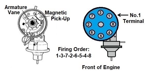
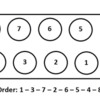
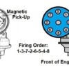
Temporarily install the new crankshaft damper and the timing pointer. Turn the crank so that cylinder #1 is set at 16° BTDC on the compression stroke (both valves closed) as per the timing marks on the crankshaft damper. Install the distributor so that a vane on the armature aligns with the metal strip in the center of the magnetic pick-up, and the rotor aligns with the #1 terminal on the distributor cap. Standing in front of the engine, looking down on the distributor, the no. 1 terminal is located at approximately 1 o'clock to 2 o'clock. Finally, the vacuum advance mechanism should point "more or less" straight ahead. It may be canted to the left just a little bit, like in the left hand diagram. This usually takes a few tries to get it right. Clamp it down in that position.
Re-use the oil pump or purchase a new standard volume pump; either way the oil pump should be taken apart, inspected, cleaned, pre-lubed, and reassembled with lock-tite on the bolt threads. The oil pump "pick-up" must be threaded and tightened into the pump prior to installing the pump. Torque the oil pump to block bolts to 25-35 ft./lbs.
DO NOT install a heavy-duty oil pump drive shaft. Use the stock oil pump drive shaft, or a stock replacement.
Install the fuel pump. The factory fuel pump was supplied by Carter. The part number for Carter's current replacement is # M6882. Torque the fuel pump bolts to 14-20 ft./lbs.
The timing cover is often badly corroded around the coolant passages, and under the coolant pump. New zinc plated timing covers are available from Summit Racing, # SES-5-65-04-201. Install a new seal in the timing cover, slip the oil slinger (deflector) on the crank snout, and install the cover. Torque the timing cover bolts to 14-20 ft./lbs. Don't forget the timing pointer.
The rubber sleeve of a 20-year-old crankshaft damper, hardened by age and heat cycling, no longer dampens as designed. The hardened rubber also allows un-bonded outer rings to “walk” on the hub; thus the timing marks are most likely incorrect. A 20-year-old damper is ready for replacement; an even older damper is long overdue for replacement.
Replace the crank damper with Powerbond's #PB1082SS damper. It is a heavy, fully bonded, steel replacement which is suitable for performance engines. The damper bolt torque spec for dampers with steel hubs is 130-150 ft./lbs. The damper bolt torque spec for the OEM damper (cast iron hub) was 70-90 ft./lbs.
Install the crank pulley too. The crank pulley bolts have two torque specs, torque "UBS bolts" to 25-35 ft./lbs, torque "place bolts" to 35-45 ft./lbs.
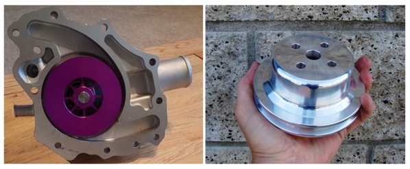
Install the coolant pump. The Milodon and Weiand coolant pumps have blocked "bypass" passages as they come out-of-the-box. The passages should be drilled open prior to installation, or a different pump should be chosen. The Pantera's cooling system performance is improved by a coolant pump designed to increase low rpm flow (Flow Kooler # 1648), and/or an over-drive coolant pump pulley (IPSCO # IPS260-OD). Torque the coolant pump bolts to 14-20 ft./lbs.
Install a wet sump racing oil pan. Choices include those manufactured by Armando, Kevko, Aviaid, and Pantera Performance Center (Dennis Quella). Torque the smaller oil pan bolts (1/4-inch) to 7-9 ft./lbs, torque the larger bolts (5/16-inch) to 11-13 ft./lbs.
Cylinder Head Assembly
It's time to finally remove the valve train checking springs and install the actual valve springs.
The factory M code or Q code valve springs are good parts, reuse them with the factory cam (1.82 installed height, 90 lbs. seated spring force, 390 lbs/in spring rate, 0.505-inch max lift). If the factory springs are reused the 7° retainers, rocker arm fulcrums, and rocker arms should be reused as well. The valve spring specs are:
• Free length (approx.): 2.05-inch
• Assembled height, pad to retainer: 1.81-inch to 1.84-inch
• Maximum out of square: 0.078-inch
• Minimum seated force: 79 lbs at 1.82-inch height
• Minimum open force: 244 lbs at 1.32-inch height
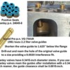
Manley Performance sells a good replacement for the Q code valve spring, it's a Street Master valve spring # 22408-16 which is a double spring plus damper (1.82 installed height, 107 lbs. seated spring force, 392 lbs/in spring rate, 0.620-inch max lift). Use it with Manley # 23645-16 valve spring retainers (7°, standard height), and Manley # 42126-16 valve spring cups (0.062-inch thick). The spring cups are fitted to the head with cutter # 41835.
Heavy duty (hardened steel or heat treated) locks are needed to mate the 11/32 inch valve stems of the new valves (single groove or 4 groove) with the factory or Manley 7° retainers.
The M code/Q code rocker arm fulcrums were made of steel (sintered iron) whereas 2V rocker arm fulcrums were made of aluminum. The M code/Q code fulcrums, if needed, are available from Melling (# MRM-1776) or Sealed Power (# MR-1811). Assemble the rocker arms and fulcrums "finger tight" for now.
Final Assembly (finishing the long block)
The OEM head gaskets had 0.047-inch compressed thickness (10.2 cc). That is also the thickness of the popular Fel Pro # 8347 PT-1 composite head gaskets.
0.038-inch head gaskets have always been a part of raising the compression of a 351C. Ford’s five layer folded head gasket # D3ZZ-6051-A (sold over the counter) and McCord’s # 6850 head gasket had 0.038-inch compressed thickness (8.2 cc). Both gaskets were mentioned often in ‘70’s and ‘80’s literature. Edelbrock (# 7328) and Mr. Gasket (# 5808G) offer composite head gaskets in that thickness today.
Bolting the assembled 61cc heads on a standard bore short block with nominal 0.035-inch deck clearance and 3 cc piston dome volume, utilizing 0.038-inch-thick head gaskets, produces about 10.06:1 compression.
Cast over-bore pistons should compensate for an over-bore by reducing compression height OR increasing dome volume (slightly dished domes). If so then 0.038-inch head gaskets will be appropriate for an over-bore as well.
The following piston dimensions maintain the compression ratio for various bores:
• Std. 4.000 bore: 1.650-inch compression height and 3.0 cc dome volume
• 4.010 over-bore: 1.648-inch compression height or 3.4 cc dome volume
• 4.020 over-bore: 1.646-inch compression height or 3.8 cc dome volume
• 4.030 over-bore: 1.644-inch compression height or 4.2 cc dome volume
• 4.040 over-bore: 1.642-inch compression height or 4.6 cc dome volume
However, if over-bore pistons have the full 1.650 inch compression height AND only 3 cc dome volume then 0.047-inch head gaskets would be necessary. This is unlikely if off-the-shelf cast pistons are employed.
Static compression and/or dynamic compression MUST be recalculated to account for alterations in deck height, alterations in compression height, alterations in piston dome volume, alterations in head gasket specs, alterations in combustion chamber volume, alterations in camshaft specs, or alterations in cam timing.
The head gaskets have a definite front and back; take caution to orient them properly. Don't forget the head dowels either.
The factory torque spec for the head bolts stipulated torqueing them in 3 steps first to 55 ft./lbs, then to 75 ft./lbs, and finally to 95-105 ft./lbs. If a head bolt, head stud, or head gasket manufacturer stipulates different torque specs they should be followed.
Old torque specs stipulating 120 ft./lbs final torque were intended only for Ford's D3ZZ-6051-A head gasket, which was a unique 5 layer folded head gasket.
Assuming 10.06:1 static compression (nominal), and the seated closure of the intake valve (IVC) occurring between 66° and 72° ABDC, the dynamic compression (nominal) shall fall in the following range:
66° IVC = 7.96:1 dynamic comp. ratio
68° IVC = 7.83:1 dynamic comp. ratio
70° IVC = 7.70:1 dynamic comp. ratio
72° IVC = 7.57:1 dynamic comp. ratio
Once the heads are torqued in place, install the push rods and fasten down the rocker arms; torque the rocker arm fulcrum bolts (5/16-inch) to 18-25 ft./lbs.
4 bbl Carburetor
The emissions tuned factory Autolite/Motorcraft 4300 carburetor is not compatible with raised compression. It's too lean, using it would result in knocking, pinging, and detonation, so it must go.
Over the years Holley has released several 600 cfm 4bbl carburetors with vacuum secondaries; they were 4160 style carburetors (no secondary metering blocks), they had electric chokes, side hung floats and single feed fuel connections. They were ALL emissions tuned carburetors. The list 6619 was one common substitute for 351 Clevelands. Horsepower was reduced by 5% with that carburetor.
"That is not the type of carburetor you're looking for".
This "de-smogged" high compression engine needs a "non-emissions" carburetor, tuned for about 12:1 A/F ratio, the kind that carries a warning "not for use on pollution-controlled vehicles". ![]()
The carburetor should be a square bore carburetor with venturis in all 4 barrels and dual high-capacity fuel bowls. That spec eliminates a bunch of carburetors. The carburetor should also have vacuum secondaries, and an electric choke. Annular booster venturis are cool, but only a "necessity" when the intake manifold is operated without exhaust heat. Select the carburetor from those sold by Holley, Quick Fuel, or Summit Racing.
The carburetor should be rated 600 to 780 cfm the way Holley and Ford rates them. Since a 500 horsepower or a 7000-rpm engine is not being assembled, a smaller carburetor (600 to 650 cfm) shall support the engine adequately. For example, Ford's first high performance engine, the 352 High Performance of 1960, made 360 horsepower equipped with a Holley carburetor rated merely 540 cfm. Ford also installed 600 cfm Holley carburetors on 390 horsepower hydraulic-cammed (W code) 427s of 1968.
If a carburetor larger than 650 cfm is preferred, its actually too big for the application; but that's OK as long as it has vacuum secondaries. As an example of that, Ford installed 780 cfm Holley carburetors on 290 horsepower Boss 302s.
There's a lesson in there somewhere. ![]()
A 600 cfm Holley has 1.25-inch primary venturis, 1.31-inch secondary venturis, and 1.56-inch throttle bores. A 650 cfm Holley has the same size venturis but 1.69-inch throttle bores. Hopefully the smaller carburetor shall serve as somewhat of a rev limiter. The smaller carburetor may also improve the powerband width and therefore low speed performance. If I were in the market for a carburetor today Holley's 650 cfm vacuum secondary carburetor # 0-80783C is the one I would purchase. Check it out.
Mount the carburetor on the engine via a dual plane intake manifold, either the Ford iron 4 bbl manifold designed for 600 cfm Autolite 4300 square bore carburetors, or the Edelbrock Performer manifold (4V # 2665, 2V # 2750). The Edelbrock manifold becomes a Ford manifold if the Edelbrock logo is removed and it is painted Ford blue ![]() .
.
Machine Shop Task #5
The Ford manifold is a 4-hole type manifold and will require having the primary bores machined open to 1.69 inches diameter. And plug the heat passage in front of the primary holes.
The tin “turkey pan” intake manifold gasket is a necessity when the intake manifold is heated with exhaust heat. It shields oil splash from the “hot” exhaust crossover below the manifold, thus extending the life of the motor oil.
Torque the smaller intake manifold bolts (5/16-inch) to 23-25 ft./lbs, torque the larger bolts (3/8-inch) to 28-32 ft./lbs.
If the intake manifold is not heated by exhaust heat, then the carburetor should be equipped with annular booster venturis, so that fuel atomization within the manifold will occur similar to how it would occur if the manifold were heated. Carburetors can be custom ordered with annular boosters from both Holley and Quick Fuel, and they're standard equipment on Summit Racing's carburetors.
Not to be Forgotten
There are external components I haven't mentioned. The thermostat, the alternator, the starter, the valve covers, the spark plugs, and the ignition wires. Service or replace them as you see fit.
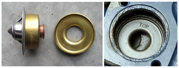
The 351C uses a special thermostat, a Robertshaw model 333. It is basically the more common Robertshaw model 330 thermostat with a flanged copper sleeve pressed on the bottom. There should be a brass orifice plate below the thermostat.
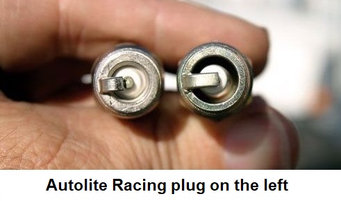
Older numbered spark plugs for an engine with 10:1 compression included Autolite AF32 (A = 14mm, F = conical seat), Autolite & Motorcraft ARF32 (A = 14mm, R = resistor, F = conical seat), and Motorcraft ASF32C (A = 14mm, S = suppressor, F = conical seat, C = copper core).
Newer spark plugs include Autolite 24, Autolite Racing AR24, or Motorcraft stock #15. Duraspark 1 plug gaps are 0.060-inch, Duraspark II plug gaps are 0.050-inch.
Conclusion
This freshened-up "351 Cobra Jet" has a potential output of 350 horsepower (320 horsepower with 2V heads), dependent upon how well the rings seal within their bores. More importantly, it would have 10:1 compression. That's where the pep, throttle response, acceleration, and low rpm torque come from.
The "de-smogged" engine's performance is a startling improvement over any "production" 351C, especially the Muskie Act compliant post-1971 versions. It's a good place to start, to figure out if going any further is even necessary.
Take It To The Limit
Add headers and tail pipes … perhaps the Hall GTS system … and the engine's output shall increase to 365 horsepower. Add a Blue Thunder manifold and the engine's output shall increase to 390 horsepower. Adding a camshaft with 0.520-inch net valve lift would nudge the output to about 425 horsepower.
A camshaft with 0.520-inch net lift would have required a long duration solid flat tappet camshaft in 1970, today that much lift can be achieved with a more street-able short duration, low overlap, hydraulic flat tappet camshaft (0.530-inch gross lift). That camshaft can be ordered, custom made, from Bullet Racing Cams specifying lobes # H274/3066 and #H282/3066, specifying 114° LSA, and specifying the indexing (timing) as 5° advanced.
Advertised duration would be 274°/282°. Duration at 0.050-inch would be 222°/230°. Gross valve lift would be 0.530/0.530-inch. The LSA would be 114° and overlap would be 50°. The hydraulic intensity is 52°.
With 114° LSA, and indexed 5° advanced, this cam should have the following timing factors:
• The seated opening of the intake valve (IVO) should occur at 28° BTDC measured at 0.006-inch tappet lift.
• The seated closing of the intake valve (IVC) should occur at 66° ABDC also measured at 0.006-inch tappet lift.
• The mathematic intake centerline (ICL) should occur at 109° ATDC, but the lobes are asymmetric, thus max-lift shall occur several degrees earlier.
An off-the-shelf alternative is Crower's camshaft # 15966. Advertised duration is 278°/284°. Duration at 0.050-inch is 220°/226°. Gross valve lift is 0.529/0.540-inch. The LSA is 112° and overlap is 57°. The hydraulic intensity is 58°.
With 112° LSA, and indexed 4° advanced by Crower, this cam should have the following timing factors:
• The seated opening of the intake valve (IVO) should occur at 31° BTDC measured at 0.006-inch tappet lift.
• The seated closing of the intake valve (IVC) should occur at 67° ABDC also measured at 0.006-inch tappet lift.
• The intake centerline (ICL) and thus max-lift should occur at 108° ATDC.
Either cam would require valve springs compatible with hydraulic flat tappet cams having higher lift rates. Manley Performance has a Street Master valve spring # 22407-16 which fits the application. It is a double spring plus damper (1.82 installed height, 126 lbs. seated spring force, 418 lbs/in spring rate, 0.635-inch max lift). Use it with Manley # 23630-16 titanium valve spring retainers (10°, standard height), and Manley # 42126-16 valve spring cups (0.062-inch thick). The spring cups are fitted to the head with cutter # 41835.
Heavy duty (hardened steel or heat treated) locks are needed to mate 11/32 inch valve stems (single groove or 4 groove) with the Manley 10° retainers.
The # 22407 valve spring matched with a 0.530-inch lift hydraulic flat tappet cam fits in well with the flat tappet street cam limits formerly suggested by Crane Cams (seated spring force 115 to 130 lbs., spring force at max. lift ≅ 330 lbs., hydraulic intensity ≥52°).
The factory spring force with the original (hydraulic flat tappet) cobra jet camshaft was 277 pounds at 0.481 lift. The spring force at 0.530 lift with the Street Master valve spring shall be 347 pounds. The stiffer push rods suggested previously will be compatible with the stiffer springs and higher lift rate of this valve train. However, if the factory rocker arms are utilized, then install them with ARP 5/16-inch chromoly bolts # 641-1500 to eliminate the possibility of bolt stretch. If the bolts are too long, then shorten them or use 1/8-inch-thick ARP washers # 200-8587.
One of Ford's rocker arm suppliers manufactured rocker arms which had push rod interference issues at 0.550-inch valve lift. The rocker arms can be identified by the trapezoid shaped “bumps” along the edges of the rocker arm, located on either side of the fulcrum. This is not a problem for a valve train employing a factory camshaft. But with a 0.530-inch lift camshaft that would be cutting things close. In that situation those rocker arms should not be used, replacements shall be needed.
-G


