Chris, the schematic posted by Joe (JFB05177) provided temperature sender ohmage for three temperatures. Its in the lower right corner. 90 degrees F = 100 ohms, etc.
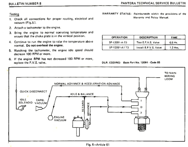
Here's the Ford documentation regarding the electric ported vacuum switch. Please note that it has 3 vacuum fittings, plus 2 electric terminals. The EPVS incorporates a switch to interrupt power to the idle solenoid, plus it manipulates the vacuum to the distributor advance mechanism. The overall purpose of the EPVS is to reduce engine idle speed by 100 rpm upon rising temperature.
Since it is actuated by rising temperature it had to be screwed into the coolant system in order to "sense" temperature.
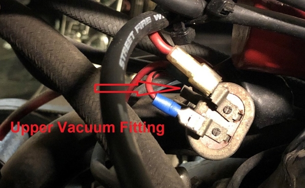
In the first picture below you can see the upper vacuum fitting, nothing attached to it.
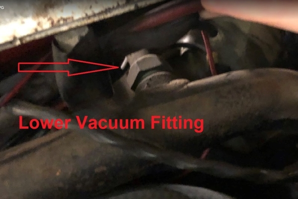
In the second picture you can see the lower vacuum fitting, nothing attached to it. It is safe to say the vacuum controls of this switch have been disabled.
"Senders" provide a variable resistance in order to modulate the current flowing through gauges. As Larry (LF-TP2511) pointed-out previously "senders" only have one electrical connection, their other connection relies upon being grounded by whatever they happened to be attached to.
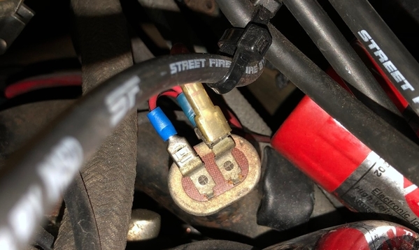
The EPVS however has two connections … because it is a switch, not a sender. True it senses temperature, a necessity of a temperature switch, but it has no provision to provide a variable resistance.
Coolant pumps are engine driven. Does it make sense to reduce engine speed, and pump less coolant, when an engine over heats? Of course not. The EPVS did more harm than good, so my advice is to always disable it.


