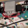
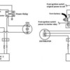
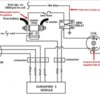
I traced my engine cutout problem to a loose wire on the ignition coil's ballast resistor. The wire was just about hanging off and barely making contact. When I pushed the connector back on, I noticed the blade terminal sticking out of the resistor was wobbly, but the other one was firm. If this wobbly terminal is causing an intermitten 'disconnect' in the resistor, would this cause the engine to shut off? Would a faulty ballast resistor prevent the engine from running?

Thanks.

Michael
Original Post

Replies sorted oldest to newest

quote:
If this wobbly terminal is causing an intermitten 'disconnect' in the resistor, would this cause the engine to shut off? Would a faulty ballast resistor prevent the engine from running?

Yes, it could, and is probably the source of your problem. Replace it.

When the starter relay is engaged, the resistor is bypassed until the key is released from the start position.

John
I have had two ballast resistors fail like that. Inside the ceramic shell is a core that the resistance wire is wrapped around. It breaks and the terminal gets wobbly. In neither case did the conductor actually break and strand me, but only because I noticed it early I think.

I'm not sure why they do this. Maybe the duraspark module pushes too much current through the ballast resistor to the coil?

I carry a spare now.
Last edited by larryw
I just spoke with MSD. They said that since I have an MSD 6AL box, that I shouldn't be using a resistor. They said running the 6AL through the resistor is like funneling a 3 lane highway down to one lane. The MSD box should be wired directly to the coil with orange on + and black on -. There should be no other wires on the coil but those two. Since I have about 4 wires on each coil terminal, I have some wire sorting to do!

Until I can get to that (and since I don't need a resistor), should I just bypass the resistor by connecting the two wires together?

Michael
FWIW, Durasparks, HEI conversions, MSD boxes etc ALL run much better without any resistor at all. THey all need 12 VDC to run effectively, having been designed for it. Note that early Panteras used a rectangular ballast off a Mustang or Galaxie while later ones (still with points 'n coil) may have a resistor wire tucked into the rear wiring loom somewhere. Remove all resistors with any electronic ignitions (unless specifically listed as NOT using a full 12VDC) or the resistor can act like a rev-limiter!
Agree completely w/ Boss. I'm a big fan of DuraSpark as they are Ford-designed and have been run on everything up to Winston Cup cars (check out some old pics of 1980s Ford Cup cars). Get rid of the resistor(s) and you can use that space to mount the DuraSpark module (I fabbed up a simple bracket for it). There is a wire in that area that provides 12V (can't remember what color) - plug that right into the module and you're on your way.
I don't think that is completely accurate, at least for the Duraspark circuit.

While you don't want to limit the 12V feed to the duraspark module, you do need a 1.3 +/- ohm resistor at the coil to limit current going into it.

Google "duraspark wiring" and in every diagram you will see a resistor shown at the coil. Maybe some modern coils don't require the resistance in the "run" mode, but most of the older oil can style do.

Later L model cars feed the ignition through a resistance wire in the harness instead of the regular wire with the ballast resistor on the firewall the early cars used.

That resistance wire can be used as a pilot wire to throw an ignition relay to feed the duraspark module, but it doesn't supply enough juice to properly run the module on it's own. But, now you will have to add a ballast resistor to protect the coil.
Last edited by larryw
quote:
While you don't want to limit the 12V feed to the duraspark module, you do need a 1.3 +/- ohm resistor at the coil to limit current going into it.

Google "duraspark wiring" and in every diagram you will see a resistor shown at the coil. Maybe some modern coils don't require the resistance in the "run" mode, but most of the older oil can style do.

Later L model cars feed the ignition through a resistance wire in the harness instead of the regular wire with the ballast resistor on the firewall the early cars used.

That resistance wire can be used as a pilot wire to throw an ignition relay to feed the duraspark module, but it doesn't supply enough juice to properly run the module on it's own. But, now you will have to add a ballast resistor to protect the coil.


So can someone clarify if the ballast resistor is requried for an e-coil (.6 Ohm Internal Resistance)?

Thanks -

Rocky
There are two coils. One to use with a resistor and one to use without.
If you eliminate the resistor, you use the coil that matches that system.
When you buy the coil, the parts guy should ask you that question.
You want to use the coil made for no resistor, presuming you are eliminating it.
You should. It can be the source of phantom ignition problems.

If you are upgrading the entire ignition to a Ford solid state ignition, this is a good time to bring in an e-coil and get rid of the can.
The e-core coils were not originally used with ballast resistance BUT the TFI ignition modules the coils were paired with utilized dynamic dwell to prevent over-charging or under-charging. Your Pantera's Duraspark II module does not provide dynamic dwell.

Since they were not used with a ballast resistance there is no precise answer regarding how much ballast resistance to use. The real question is, can you use the e-core coil without ballast resistance AND without dynamic dwell? A coil that over charges will run hot and will fail more quickly than normal. I don't know how robust those coils are. Give it a try and see what happens. You might want to keep a spare coil in the car ... just in case. If you want to install some ballast resistance, installing a resistor with approximately the same resistance as the primary resistance of the coil will get you in the ballpark.

Unless you've installed a separate supply for ignition power, a section of the original wire that supplied power to the coil had ballast resistance built into it (Pantera L). So your coil power may have ballast resistance. Unfortunately if that same wire is used to provide power to the ignition module it shall have ballast resistance too; the module supply is not supposed to have ballast resistance. The power for that wire passes through the ignition switch, and there's usually some resistance associated with the ignition switch too. I would suggest you bypass that entire circuit so you can control exactly how much resistance is in the coil circuit.

Make sure the ignition is performing up to spec before you install the e-core coil, this way you can make a valid before and after comparison. Check to make sure the ignition module and coil are wired properly. Install a new distributor cap & rotor, install a new Duraspark II "oil can" coil, replace the central plug wire and gap the plugs properly.

Unfortunately the performance of a Duraspark II ignition is not much better than a breaker point ignition, the main benefit being there's no points to adjust. No argument the e-core coil is a better coil, but you're triggering that excellent coil with a low-performance fixed-dwell, sine-wave pulse triggered ignition.

Ford has built some excellent performing ignitions over the years:

(1) Crank trigger, EDIS-8 module & EDIS coil packs (dynamic dwell, precision trigger, electronic timing)
(2) TFI-IV distributor, TFI-IV module & e-core coil (dynamic dwell, Hall-effect trigger, electronic timing)
(3) MSD distributor, Duraspark I module & Duraspark I coil (dynamic dwell, breakerless trigger, mechanical timing)

Dynamic dwell means the coils are properly charged from idle to high rpm, never over-charged or under-charged. All ignitions with fixed dwell over-charge the coils at low rpm and under-charge the coils at high rpm. An over-charged coil runs hot and its life is shortened by the heat, an under-charged coil has reduced spark energy.

There's one caveat with the TFI-IV system ... use a late model remote mount TFI module and put it in the passenger compartment away from the heat of the engine compartment. There was a massive class-action law suit regarding the TFI ignitions with modules mounted to the sides of the distributors. The TFI modules failed due to engine heat.
I asked my expert on this and this is his reply.

The type of coil, either E-coil or can coil does not determine if a resistor is used. (there are other laminations other than E as well) It's the resistance of the coil that's critical and the control of the coil determines if a resistor is needed. When points control the coil in most to all cases a ballast resistor is needed. The coil is actually rated at a lower voltage for starting.

Electronic, MSD (and other CD), capacitive discharge is very short, it can only fire 1 to 3 times but spark duration is in microseconds. Therefore a resistor is not needed.

Electronic, Variable dwell, Ford & GM, inductive discharge, current is limited by the coil driver electronic device, either by varying length of time, or learned then stored in memory (GM). Any kind of coil has a time constant or a rate of current increase, this can be used to limit the current by stopping the current increase at a point in time. Therefore a resistor is not needed.

Electronic, PE (Pantera Electronics), Coil current is not dwell dependent, it is a proprietary design and a resistor is not needed.

The maximum spark time length is several milliseconds, over 100 times the spark length of CD.


Just passing this along. Hope it helps. Smiler
Well, that's the way electrical engineers speak Rocky. It's kinda' like Einstein writing Shakespeare.

http://www.youtube.com/watch?v=BWi-ZgaSCEw

Their hearts are in the right place, they just don't get the nuances necessarily of the spoken language? Makes sense to them.

They impressed the other Ph.D.'s with their paper that's how they got theirs?

Here's a neat video showing the P-E ignition firing and self cleaning a fouled up spark plug.

For me, this is perfect with the Webers. No way will an MSD do this. Went through a lot of plugs with mine, when THEY were working. Then they would just stop, like you had to put another quarter in the change box?

In fact an MSD WILL NOT FIRE A FOULED PLUG! I just don't understand why anyone knowledgeable would use them, unless someone gave you their broken one? Plenty of those around for sure.

http://pantera-electronics.com...files/FouledPlug.MOV

Basically what the above quote means is that only a points fired ignition needs a ballast resistor and that the P-E unit can not over heat or under fire the coil.

You put the hottest flame throwing e-coil in it and just stand back and make sure it doesn't think you are a spark plug? Man that hurts! Smiler


What exactly the MSD unit needs, besides dependability, everyone is still trying to figure out? It's really outdated '60s CD technology.

Additional ignition information: Just in case you got bored Rocky, munch on this?

Pantera-Electronics Inductive Engine Ignition Controller.

The most significant advantage of inductive ignition systems is that inductive coils are generally more efficient than capacitive discharge coils as they can provide longer spark duration that can ensure complete combustion. The ability to provide longer spark duration is because inductive coils only provide enough energy to cross the spark gap; the remaining energy from the ignition coil is used to maintain the spark.

Electronic capacitor discharge ignition (CDI) systems have been common on internal combustion engines because the technology has been in use since the 1960's. Capacitive discharge coils release almost all of their energy instantaneously, therefore considerably reducing the amount of energy available to maintain the spark.

Capacitive discharge ignition systems work by storing energy in an external capacitor, which is then discharged into the ignition coil primary winding when required. This rate of discharge is much higher than that found in inductive systems, and causes a corresponding increase in the rate of voltage rise in the secondary coil winding. This faster voltage rise in the secondary winding creates a spark that can allow combustion in an engine that has excess oil or an over rich fuel air mixture in the combustion chamber.

The high initial spark voltage avoids leakage across the spark plug insulator and electrodes caused by fouling, but leaves much less energy available for a sufficiently long spark duration; this may not be sufficient for complete combustion in high compression, turbo or supercharged engines. With inductive ignition systems more energy can be delivered to the secondary winding of the coil than in a capacitive ignition system. In fact, with the same power supply current, up to five times more energy can be delivered to the secondary winding of an inductive ignition coil than to a capacitive discharge coil.

Typically a capacitive discharge system will deliver a maximum of 10 millijoules of energy compared to an inductive ignition system delivering more like 50 millijoules of energy and potentially in excess of 100 millijoules. This large difference in supplied energies will mean an inductive system can provide spark duration of 2000 microseconds or more in a single spark, compared to 600 microseconds for a capacitive system.

Ignition in lean fuel mixtures by capacitor discharge systems can sometimes be accomplished by the use of multi-spark ignition, where the ignition system duplicates the prolonged spark of inductive spark systems by sparking a number of times during the cycle. The multi-spark ignition typically functions to a maximum of 3,000 RPM. This limitation is due to the time required to charge the capacitor.

The high energy and long spark durations are a considerable advantage since they provide better ignition of lean or non-homogenous air/fuel mixtures. In many cases engines that are unable to meet emission standards with capacitive discharge systems can be bought into compliance with electronic inductive ignition systems.


...and,

You still don't need a ballast resistor

The Ford Duraspark is a VERY nice generic set up for a Pantera, I DEFINITELY AGREE but it is a generic set up. Problem is the Pantera is specific and has specific requirements. The P-E unit is the specific unit UPGRADE to the Duraspark THAT I NEEDED.

ANYONE RUNNING WEBERS IN A PANTERA NEEDS THE P-E IGNITION! You will see the difference.

Ignitions do not make horsepower for you. You want to minimize the amount of power that you loose from it's lack of efficiency. The anti-fouling, plug cleaning feature of this ignition is what you expected from the MSD but never got from it.

I'd still rather just say, try this, it works. Reading ALL this technical stuff just gives me a headache? Just like Sherman does.

I guess it's kinda' like the Niagara Falls routeen. Just don't say, Niagara Falls! You'll just start him up all over again! Roll Eyes
Last edited by panteradoug
I am in the final stages of replacing a DuraSpark II unit with DuraSpark I unit following George's instructions. I have two questions on the coil wiring. For the positive side of the coil, do I use the Bl/BK wire that was going to the plug that connected to the ballast resistor that previously passed thru to the + side of the coil (in George's pic this is labeled "lite blue") or the PK wire that went to the ballast resistor? Then on the negative side of the coil, I have the green wire from the Duraspark - Do I need to add any other wire to the negative coil terminal to send a signal to the tach?" Thanks
The OEM wiring supplying power to the coil can be problematic in terms of supplying full voltage to the Duraspark coil. In some instances it was a resistance wire. In ALL cases its power passed through the ignition switch, which normally has very dirty contacts. Any bad connections will also create a voltage drop.

I recommend not using the OEM wiring to power the ignition, rather installing a relay to supply power directly from the battery. The wire which previously provided power to the coil (coil's + terminal) can be used to pull-in the relay. The relay then supplies power to the red wires (or red with green stripe) which power-up the positive terminal of the coil and the Duraspark module.

The wire which originally supplied the tachometer (coil's neg terminal) will need to be spliced into the green wire circuit (or green with light green stripe) between the coil negative terminal and the Duraspark module. Often the horse shoe shaped coil connector will have an additional "spare wire" attached to the same side of the connector as the green wire, specifically to provide for a coil connection.

I don't have a definite reply for you in terms of OEM wire colors, but I would guess the black wire with blue stripe is the tachometer wire. If you have a volt meter or "tester" you can verify this by turning the key to the run position, the tachometer wire will not supply power, the coil power wire will.

Attachments

Images (1)
  • Duraspark_I_wiring
George - thank you for the response - attached is photo of my set up for which I followed your instructions and I am using a relay- now I have more questions.

If I don't use the OEM wiring to supply power to the positive side of the coil, what source should I be using to power the coil?

You say "The wire which previously provided power to the coil (coil's + terminal) can be used to pull-in the relay." If this is the case, this is what i was planning to do and I was asking whether the pink wire or blue/black wire (they are together in a two prong plug) that went into the ballast resistor then from the resistor to the coil would be the right wire to attach to the 86 terminal on the relay - please advise

Similarly, you indicate "The wire which originally supplied the tachometer (coil's neg terminal) will need to be spliced into the green wire circuit (or green with light green stripe) between the coil negative terminal and the Duraspark module. While I don't see this on your wiring diagram that I am following, this can easily be accomplished as I can add a ring terminal to the OEM blue/black wire and connect that to the negative side of the coil - Correct?

Finally, I can't turn the car on now to do any tests - it's all apart and at this point in the restoration, I am cleaning up all the harnesses and adding the Duraspark and a GM 94 AMP alternator.

I look forward to getting your insights on this - Thank you

Attachments

Images (1)
  • duraspark_wiring
Last edited by George P
quote:

Originally posted by 427390:

... If I don't use the OEM wiring to supply power to the positive side of the coil, what source should I be using to power the coil ...


The diagram I posted above makes this graphically clear. A picture is worth 1000 words, etc.

quote:

Originally posted by 427390:

... I was asking whether the pink wire or blue/black wire ... would be the right wire to attach to the 86 terminal on the relay ...


The black wire with blue stripe should be the tach wire. But I "should" also be rich and handsome.

That leaves the pink wire for the other chore. But rather than taking my educated guess as gospel, I suggest you wring-out the wiring in some way.

quote:

Originally posted by 427390:

... The wire which originally supplied the tachometer (coil's neg terminal) will need to be spliced into the green wire circuit ... I don't see this on your wiring diagram that I am following ...


This is also on the diagram I posted above.

quote:

Originally posted by 427390:

... this can easily be accomplished as I can add a ring terminal to the OEM blue/black wire and connect that to the negative side of the coil - Correct ...


Incorrect. The proper Duraspark I coil uses a very specific coil with a "slip-on" horse shoe style connector. It doesn't have threaded connections, and has no way for ring terminals to connect to it. The SMP part number for the Duraspark I coil is FD477.
I run a 15A fuse and have never had it blow. I believe I got that number from one of the Duraspark installation pages.

Note that it is easy to burn up a Duraspark Module (and/or coil) by leaving the ignition on without the engine running. This will occur without blowing the fuse.

Don't ask me how I know.

An ignition buzzer or light is your friend here.


Rocky

PS. Your setup looks pretty conducive to being able to test the whole assembly before you mount it in the car. Just hook up a distributor, and run a common ground from the distributor body to the mounting plate and battery minus. You have to work out the power (+) to the Solenoid and the ignition "On" relay connect (minor jumpers).

Spark plug wire / spark plug wire to the coil, and turn the distributor, and Viola! Sparkage! (Spark Plug Tip close to the distributor body).
Last edited by rocky

Add Reply

Post
×
×
×
×
Link copied to your clipboard.
×