Seems I don’t get to drive or work with my car much as I’d like to these days and seldom have it out after dark. Last night I did and my headlights failed. The headlights wouldn't pop up and the lights wouldn’t turn on. Even after manually actuating them, when I'd turn the ignition switch, they'd just retract irrespective of headlight switch position. It resulted in a two mile drive home in the dark. I can cross that one off the bucket list. Roll Eyes

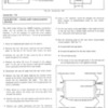
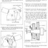
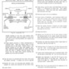
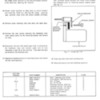
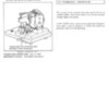
I’ll spare you all the details but it turns out the headlight switch took a dump. When I removed it from the panel it almost fell apart. They seem to be notoriously fragile from the various threads I’ve read here. While I was troubleshooting, I discovered my headlight door relay was wired very strangely. A couple of the wires fell off before I could get it completely loose but I’m not even sure how it could have even worked (but it had). It had a 12 gauge blue wire that was switched to 12v from the ignition switch with what appears to be a 30A circuit breaker. The breaker was mechanically mounted with one of the headlight relay screws. Why would you need a 30 amp breaker on the headlight motor circuit? I removed it because there was already a 12v supply to the relay. Here’s a picture of the circuit breaker. Anyone recognize this?


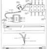
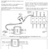
I rewired it per the schematic below.


In the mean time I removed the switch and made a jumper for the wires and all is fine now at least temporarily. I think I’ll make the recommended mods to the headlight circuit such as others have done and described my Mike Drew here to add a couple relays and get the headlight current of the switch.

http://www.panteraplace.com/page116.htm

I see the vendors have replacements. So does anyone have a spare headlight switch for sale with chrome bezel and ‘LIGHTS” script like this one?

Last edited {1}
Original Post

Replies sorted oldest to newest

So I take it that it was supposed to protect the portion of the circuit that was unfused?

Does anyone have a schematic that shows this component? As I mentioned, my headlight door relay had been rewired, at least contrary to the schematic in my previous post. The breaker was inline with what appeared to be a new switched 12v source which I suspect was also unfused but I cannot be sure.

In my current configuration, I would place the breaker on R/Blk power but this already emintaes from fuse 10.

I'd like to see the sevrice bulletin. If anyone has it, a post would be greatly appreciated.

Best,
K
Thanks a bunch John. That was very helpful and cleared up a few things.

Figure 19 was indeed how my relay was wired. I had figured out that the internal pin connection wasn’t present on my relay by observation and volt meter but just chocked it up to DeTom/Ford documentation of teh era not being an exact science, sort of like having a D16Y and D46Y relay that are different parts but not identified as such Roll Eyes

Where is the connector block in referenced figure 18? Is it up behind the dash somewhere? It appears from my wiring diagram that the other side of the connector block may go to the ignition switch? Is this the case?

The TSB is prescriptive but does not explain reason for the mod. Were people popping 30A fuse 10 with by raising the headlights with the other components on the circuit in simultaneous use…..maybe limiting current and headlight motor speed? Hmmm.

The configuration in my previous post is a fairly conventional motor reversing limit switch circuit that I have seen before. It doesn't do so well when a limit switch fails. I haven’t fully absorbed the Mike Drew article at the link in my previous post but I’m leaning toward that route.

Thanks again.
Kelly
Something not shown on the schematics is the fact that the headlight motor actually draws its power from a jumper wire off the headlight switch; it does not go back to the fuse box. There's two possible male spade lugs available on the side of the switch. Having the jumper on the wrong one will allow the lights to come on but not rise since the lights are one circuit and the motor is another. The lowering function after manually raising the buckets seems to be yet a third power line, probably associated with the limit switches. I ran into this on a '72 and a '73 L model (different colored wires on each, by the way).
quote:
Is it up behind the dash somewhere?

Yes, near the steering column.
quote:
It appears from my wiring diagram that the other side of the connector block may go to the ignition switch? Is this the case?

yes
quote:
It doesn't do so well when a limit switch fails.

Actually, those limit switches do not have a reputation for failure. What does, as you found out, is the console light switch.
quote:
I haven’t fully absorbed the Mike Drew article at the link in my previous post but I’m leaning toward that route.

Indeed, EVERY Pantera should have that relay modification done in one way or another. There are at least two owners that sell pre-fabricated kits to do so.

Larry
quote:
Originally posted by Bosswrench:
Something not shown on the schematics is the fact that the headlight motor actually draws its power from a jumper wire off the headlight switch; it does not go back to the fuse box. There's two possible male spade lugs available on the side of the switch. Having the jumper on the wrong one will allow the lights to come on but not rise since the lights are one circuit and the motor is another. The lowering function after manually raising the buckets seems to be yet a third power line, probably associated with the limit switches. I ran into this on a '72 and a '73 L model (different colored wires on each, by the way).


Thanks Jack, I'm not sure what caused the failure. I think it was either the headlight switch itself (most likely) or a perhaps a fouled limit switch which caused the lift circuit to remain open even when the headlight switch position called for it to be energized. I suppose it could be a different limit swicth failure that resulted in high current and helped the switch fail. The switch failure looked to be mechanical, not electrical.

Near as I can tell the headlight motor is powered to actuate the headlight doors down anytime the ignition switch is on and when the headlight switch is off (or removed) and it's only the down limit switch that opens the circuit in this condition. So if the the headlight switch completely fails (in a manner like it has been removed), you get neither an up signal nor lights. Make sense? We'll see. It is now wired in the pre-TSB 14 configuration and if I jump the the pink to red/white wires on the switch, the headlight relay changes state and the headlights come on and happily pop up.

Kelly
Last edited by panterror
quote:
Where is the connector block in referenced figure 18? Is it up behind the dash somewhere? It appears from my wiring diagram that the other side of the connector block may go to the ignition switch? Is this the case?

It is located above the steering column, and is connected to the ignition switch.

quote:
The TSB is prescriptive but does not explain reason for the mod.

Correct, it does not. I'm not sure why this mod was done. Note that the circuit breaker that is call out (bottom of pg 13 of the TSB) is a "Non-Cycling" type. I don't think that there is a manual reset button on this breaker, which means that, once tripped, the breaker must be replaced. This may have been done as a deterrent to keep someone from replacing fuses (multiple times) before they looked for the source of the problem.???

quote:
The configuration in my previous post is a fairly conventional motor reversing limit switch circuit that I have seen before. It doesn't do so well when a limit switch fails.

It is a simple double pole, double throw (DPDT) relay. Since the limit switches pass the full current of the door motor, if one limit switch fails in the open position position, then the doors won't function. If one limit switch fails in the closed position, then there will be big trouble in River City.

Referring to TSB Article No. 117, Fig. 19 (pg 14), it appears that one terminal of the relay coil is connected to the +12 via the circuit breaker, and that the other coil terminal (red wire at bottom left) is grounded via the headlight switch.

Referring to TSB Article No. 117, fig. 18 ('71 through early '74 cars), the black wire (bottom right) goes to ground, and the red wire (bottom right) receives power from the headlight switch (but only when the headlights are turned on).

I recently replaced a headlight door motor relay (for another Pantera owner) with a standard "off the shelf" relay and will do a write-up soon.

The Mike Drew relay mod is for the headlights only, and has nothing to do with the headlight door motor circuit.

John
quote:
I suppose it could be a different limit swicth failure that resulted in high current and helped the switch fail.

Kelly,

The current that flows through the limit switches, motor, and relay does not pass through the headlight switch. Only the headlight door motor relay COIL current (very low current) goes through the headlight switch.

John
quote:
The current that flows through the limit switches, motor, and relay does not pass through the headlight switch. Only the headlight door motor relay COIL current (very low current) goes through the headlight switch.


quote:
The Mike Drew relay mod is for the headlights only, and has nothing to do with the headlight door motor circuit.


Got it. Guess I was thinking of "Drew Mod" with respect to getting the high (headlight current) current off the headlight switch.

quote:
If one limit switch fails in the closed position, then there will be big trouble in River City.


Yup if they fail to open the circuit at limit....something's gotta give.

I've never blown a fuse of any kind in my Pantera. In the pre TSB14 configuration, it appeared that the power source is the red/black trace that is fused at the 30A "fuse 10", so I thought it looked OK, at least as good as it ever was, though that fuse also looked like it had the heater fan and the anti-icing switch (whatever that is) hanging on it.

Thanks for your help.

Best,
Kelly
Post
×
×
×
×
Link copied to your clipboard.
×