After installing my Pertronix Ingitor III I’ve been working at optimizing my initial ignition timing. Has anyone already figured out the measurement/distance of one degree on the outer edge of the flywheel as seen through the bell housing inspection window. I’m getting tired of taking the firewall out to adjust the timing and would like to use the flywheel for timing. I know how to figure out the distance of a degree on a circle but it is difficult to determine the circumference as viewed through the window with everything assembled.

If you have this figured out, what area on the flywheel did you use and the distance of one degree? I have a stock flywheel and clutch cover.

Mike
Original Post

Replies sorted oldest to newest

Mike, I'm also getting tired of removing the firewall cover as I continue to dial in the distributor timing. Glad you brought it up.

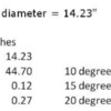
Assuming the diameter of a 164 teeth Cleveland flywheel is 14.23" (based on three different Ford Web sites quoting same 14.23" figure), I calculated the circumference. Divide the circumference by 360 for degrees/inch and by 164 for degrees/tooth. Once we pick and mark the TDC tooth and corresponding point at the edge of the inspection window, we should be able to mark the flywheel with the advance timing points of interest. I think I got this right and just may try it out if I have time this weekend to see if my flywheel timing marks match the damper timing marks.

Ron

Attachments

Images (1)
  • Flywheel_degrees
Thanks Ron. After looking at the flywheel through the inspection window it looks like the best solution would to file a line at the center of the outer edge of the window and then scribe the degree marks along the outer back edge of the flywheel that would be just under the file mark. Can’t tell for sure but it looks like I can see the outer edge of the flywheel with the ring gear just out of sight inside the window. The clutch plate and pressure plate are very visible but I’m not sure that an 11” clutch plate is exactly 11”.

So far my engine really likes a bit more advance!!

Mike
Last edited by pantera1887
quote:
Originally posted by PanteraTurbo:
Not sure about degrees vs diameters and such but if you make a mark on the Bellhousing and flywheel at TDC and purchase a dial back timing light its no problem.


Great idea, but I’d hate to give up my good old made in the USA 70s vintage timing light!! Seems to work with the Ignitor III multi spark too!

Mike
In the time it takes you to figure this out I could R&R the engine cover 10 times ! Big Grin

All kidding aside. Trying to accurately do this through the bell housing inspection hole would seem difficult. Unless your markings were perfect. on the flywheel wouldn’t your scribing leave a large margin for error?

Great idea, maybe some vender could produce a trick new SS or aluminum flywheel with these markings.
Last edited by Pantera 3rd&Last
Take your best guess for the TDC mark, and use a marker or crayon to mark the flywheel. Then check this mark against the balancer mark with the engine at idle and move it if necessary (engine off of course Big Grin). Once TDC is established, mark the other increments as needed and verify with the timing light.

Once you have established and verified the marks, you can make them permanent (scribing, punching, whatever).

The best way to verify the marks would be to have two people, both with timing lights, preferably with dial back timing lights.

One problem that I see here is that the "pointer" mark that is placed on the bellhousing is too far from the flywheel. This allows an error to occur, as your eye and the timing light must be in the exact location each time, or there will be an error of several degrees in the timing marks. Notice how close the timing pointer is to the harmonic balancer.

As an example, hold up both of your index fingers 6 to 12" directly in front of your face. Align the two fingers so that they are in line with each other (one in front, and the other behind) and appear as one. Without moving your fingers, slowly move just your head to the left or to the right. The finger closest to you represents the "pointer" mark on the bellhousing, and the other finger represents the mark on the flywheel. The fingers appear to be out of alignment when you move your head, but they are not (relative to the starting position of your head). This is called parallax.

This example uses greater distances than are found on the bellhousing to flywheel, but your fingers are much wider than your flywheel timing marks. Wink

John
quote:
Originally posted by Pantera 1887:
One possibility would be to set the engine at TDC for number 1 with the damper marker at 0, then mark the flywheel, turn the engine to 10, mark that, then 20, then 30 and 40. Might need to mark it in smaller increments with 10 equaling 1.24”.


That's exactly my plan of attack, Mike.

Ron
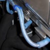
Cool! It works pretty neat. I’ll be putting the details of how I did it on Pantera Place. I marked 0, 10, 20 and 30 so I could use my existing made in the USA 70s vintage timing light. You have to strobe it from under the wheel house brace so you get a nice straight on view of the timing marks. I was never able to do that on the front pulley. The marks show really well.

Mike

Attachments

Images (1)
  • DSC04076
Post
×
×
×
×
Link copied to your clipboard.
×