I recently got a 100 amp alternator from PI. I installed it with a new external regulator from Checker. Life was good. Lots of amps. Parked it on Monday. Fired it up on Friday to prepare for Autocross this weekend and charging was gone.

I took the alternator and had it bench tested. All OK. Returned and got another regulator. Checked the continuity of the orange and green wires,field and stator. I removed the wires from the connector to tighten them up. I hooked the wires up directly to the regulator. Stared the car. I have constant battery power on the yellow wire. None of the other wires show any voltage using a 12 volt test light or a DVOM. I checked the case ground and it was fine.

Could I have gotten 2 bad voltage regulators?
Original Post

Replies sorted oldest to newest

I would double check the grounding of the regulator AND the alternator. even try a heavy wire between the two and to ground.

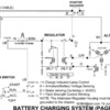
when you turn the key (but not crank) do you get the warning light and have 12VDC on terminal "I"
there should be some voltage at "F" to flash the field even when the alternator is not spinning

Is the regulator the relay or solid state type?

Attachments

Images (1)
  • BATTERYCHARGINGSYSTEM(PAGE1)_000001
Last edited by jfb05177
The alternator is case grounded, and does not normally require a separate external ground wire.

The voltage regulator case needs to be grounded.

As JFB asked, is there voltage at the regulator's "I" terminal when the key is in the run position, and is the "GEN" light in the tach on?

With the key off, only the "A" terminal will have 12VDC.

John
While it may seem like a side track with the internal regulator discussion, the point to be taken is that it may be that the "I" terminal of the solid state regulator needs full voltage to switch on and flash the field to get the alternator/regulator working. The "turn on" voltage my be just marginal and thus worked originally but now doesn't.

If you know the application of the regulator being used, maybe a schematic can be found to verify
Voltage at the "I" wire is from the ignition switch that tells the regulator to start working. with the old mechanical, the "I" voltage was used to provide the initial field current so when the alternator spins it will make current and become self substaining. (it sometimes possible without "I" to race the engine and residual magnatism in the field get the alternator/regulator working.

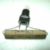
the resistor around the indicator bulb is to provide a path of current to the "I" terminal in case the bulb is out. If you don't have voltage at "I" when ignition switched on, you could make a monetary jumper to "I" while spinning to flash the field and get it working. (or even use a toggle to provide "I")

BTW, did you go to the autocross?
Last edited by jfb05177

Add Reply

Post
×
×
×
×
Link copied to your clipboard.
×