

By moving the bumper closer to the body, it is apparent the inside curve of the bumper is less than the rear body panel curve. Perhaps, if you cut the inner line of the bumper to match the body curve it may enhance the appearance.
Did you see this cool flywheel? Now it's degreed on every cylinder pair at 0 Deg, 16 Deg and 36 Deg.
Yes, I did.
Please tell us more.
Steps involved? At home or??
Intended bell housing marker point??
Inquiring minds want to know.
Larry
Yes, I did.
Please tell us more.
Steps involved? At home or??
Intended bell housing marker point??
Inquiring minds want to know.
Larry
Hey Larry -
My buddy Wade (Mark IV/4280) has a mill with a rotary table on it.
He basically uses the orientation of the bolt pattern on the flywheel to find the TDC point for the 1/6 cylinder pair on the flywheel.
I am sure he has this reference orientation preset from working on many Ford motors.
Update: He is less tricky than I thought. He just set the motor to TDC via the front balancer, and then marked out the window on the flywheel using the bellhousing. Once the limits of the window were defined, he just marked the degree marks so they would be inside the window.
Once he sets his cylinder 1/6 TDC reference - everything else is based on this. It then becomes basically an engraving job.
His rotary table is adjustable, and in my case, he just just marked off the 1 deg increments for the 1/6 cylinder pair. The 3/5, 7/4 and 2/8 didn't get the same level of detail, but just the key points.
Update: The other cylinder pairs are marked at 0*, 14* & 16* and 34* & 36*.
The intent is to allow a convenient reference for "quick checks" using any cylinder wire.
The reference is set on the bellhousing by initially setting the timing at the front harmonic balancer & timing pointer (e.g. Cylinder 1 - 16 Deg. static advance at idle). The flywheel has a corresponding 16* reference mark milled into it.
Once the static timing is dialed in (and verified) on the harmonic balancer in front, we just went to the little window in the back of the bell housing, and then use the 16* mark to set the reference into the bell housing. Basically we took a sharp file, and cut a line in the aluminum housing as our timing pointer.
Having a mill with a rotary table is the key to this.
Hope this explains the process.
Rocky (a.k.a. Chuck)
quote:Did you see this cool flywheel? Now it's degreed on every cylinder pair at 0 Deg, 16 Deg and 36 Deg.
I like it Rocky and was thinking of doing something similar. I've frequently seen Panteras with flywheels marked at TDC or certain number of degrees advance for quick timing checks but that takes it a step further in convenience for running valve lash. In my case, I have a McLeod Street Twin and the pressure plate carrier covers the entire flywheel so markings would need to be on the PP carrier instead of the flywheel. I have a 14" Jomar degree wheel and was going to cut the center out it and mount it under the PP bolts but got a little squeamish about it at 7k rpm(one side is marked 180-180, otherwise the degree markings would be in the wrong direction for rear install). I think I'm just going to mark the PP with an etching pen instead. -Might be an alternative for anyone doing something similar on already assembled engines but you might need a degree wheel instead of harmonic balancer for desired accuracy. Accuracy is one very nice feature of the method Rocky shows in his post.....it's like having a built in 14" degree wheel permanently installed.
quote:Basically we took a sharp file, and cut a line in the aluminum housing as our timing pointer.
Another alternative is to drill and tap a small hole, and make a sheet metal pointer. It's adjustable to a degree and a new pointer with offset can be made if desired. This can also be done with the BH installed in the car.
Keep the build pics coming Rocky.
Best,
Kelly
Attachments
Images (1)

Thanks, Kelly - Cool idea on the pointer.
Finally decided to get started on my "Reduced Hump Bulkhead Cover" construction. My plan is to have the center cover attached via Velcro, so I can just pull it off, and access the metal engine cover from inside, without pulling the whole big piece off.
This project will be ongoing until I get a couple more parts for my ZF (on the way), and then will likely go into a holding pattern until I get the motor & transaxle installed.
Anyway - I already had the reduced metal engine access cover, and all of the accessories (Sanden Compressor, and 1G alternator outboarded) - this was fabricated on my last build. You can see pictures on about page 4 of this thread.
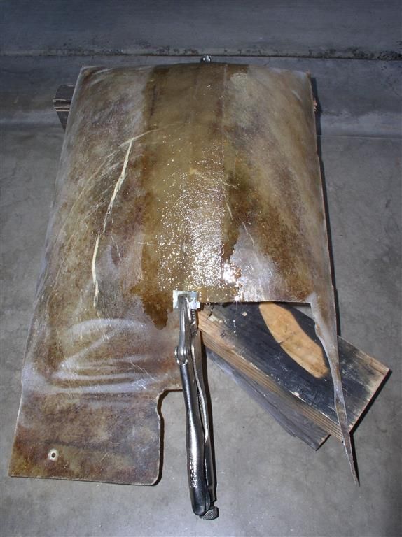
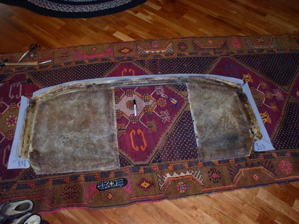
Now I am starting with a reasonably OK rear bulkhead cover. It had some rips in it, so it would have needed reupholstering anyway.
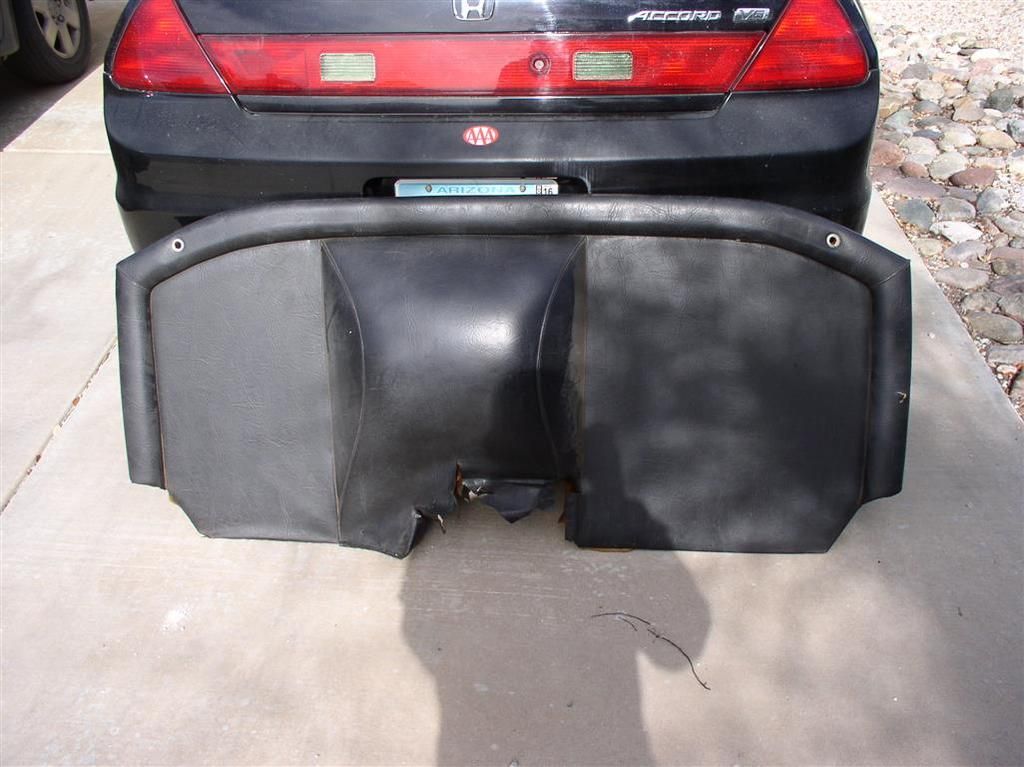
I stripped off the upholstery and foam, to reveal a fiberglass cover in good shape. I kept the vinyl to match the fabric, and to help me with the sizing when I go to reupholster it.
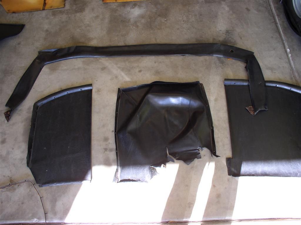
I plan to do the upholstery on the big pieces (the outside) myself. I will probably take the "hump" part to a professional - maybe. It seems like the hardest part will be sewing the seams accurately.
I stripped off all the foam on the inside and outside, and hit it with a wire brush on my angle grinder. It cleaned up nicely.
Then I cut the center section out with my angle grinder.
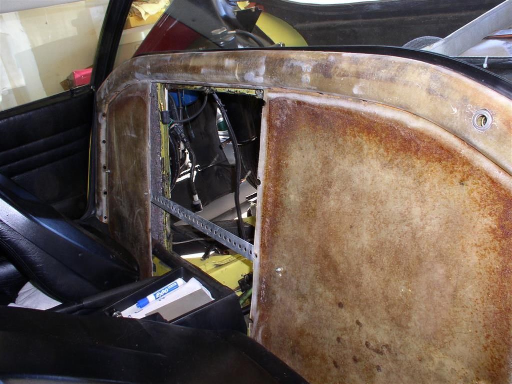
I was worried about the thing breaking at the top, so attached a temporary support piece.
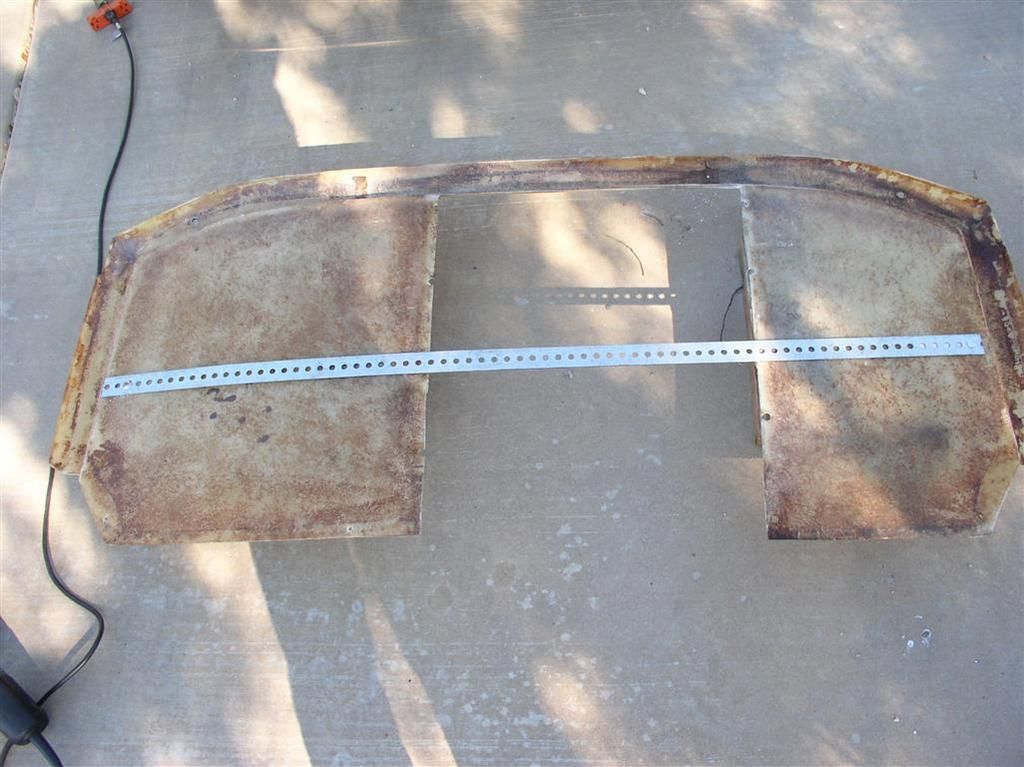
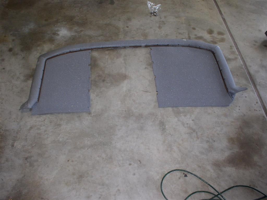
This part fits nicely in the car. Now to start on the hump tomorrow (when I can get out and buy some sheet metal and fiberglass resin. Maybe I will look for foam and vinyl at the same time.
Here's couple more pictures in a slideshow.... Watch this space for more pictures.
Slideshow of Reduced Bulkhead Cover Construction....
Rocky
This project will be ongoing until I get a couple more parts for my ZF (on the way), and then will likely go into a holding pattern until I get the motor & transaxle installed.
Anyway - I already had the reduced metal engine access cover, and all of the accessories (Sanden Compressor, and 1G alternator outboarded) - this was fabricated on my last build. You can see pictures on about page 4 of this thread.
Now I am starting with a reasonably OK rear bulkhead cover. It had some rips in it, so it would have needed reupholstering anyway.

I stripped off the upholstery and foam, to reveal a fiberglass cover in good shape. I kept the vinyl to match the fabric, and to help me with the sizing when I go to reupholster it.

I plan to do the upholstery on the big pieces (the outside) myself. I will probably take the "hump" part to a professional - maybe. It seems like the hardest part will be sewing the seams accurately.
I stripped off all the foam on the inside and outside, and hit it with a wire brush on my angle grinder. It cleaned up nicely.
Then I cut the center section out with my angle grinder.
I was worried about the thing breaking at the top, so attached a temporary support piece.

This part fits nicely in the car. Now to start on the hump tomorrow (when I can get out and buy some sheet metal and fiberglass resin. Maybe I will look for foam and vinyl at the same time.

Here's couple more pictures in a slideshow.... Watch this space for more pictures.
Slideshow of Reduced Bulkhead Cover Construction....
Rocky
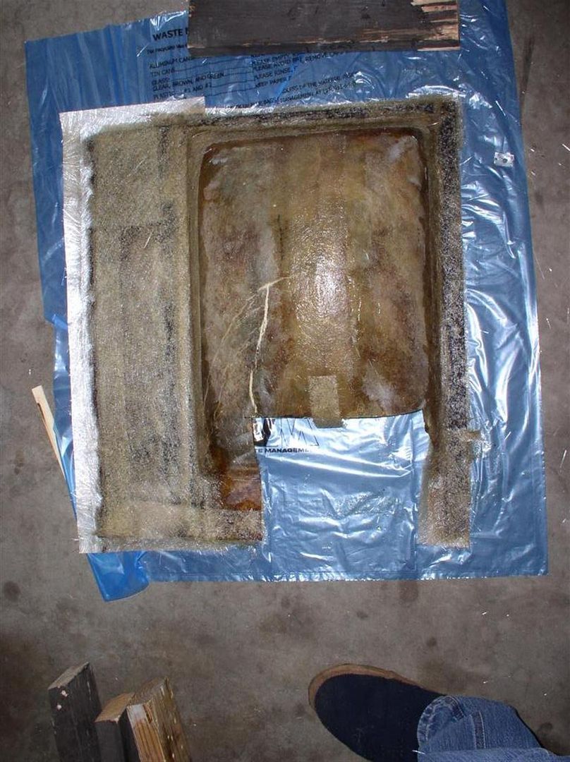
Making a little more progress. The main panel is now fully cut and aligned. I am starting to realize this is a bigger project than I thought it was....
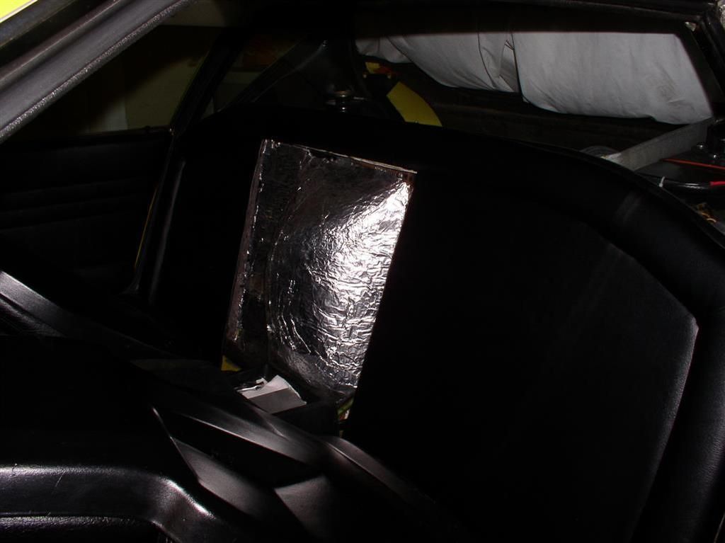
I also found out I can easily fit 1" Styrofoam insulation behind the fiberglass bulkhead panel (in the permanent part).
The Hump is glassed over (joined).
Rocky
I also found out I can easily fit 1" Styrofoam insulation behind the fiberglass bulkhead panel (in the permanent part).
The Hump is glassed over (joined).

Rocky
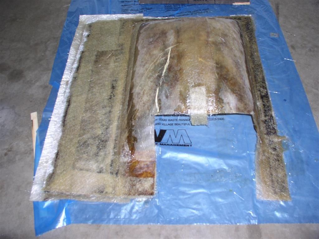
Progress continues (albeit slowly)...
Still waiting on ZF parts, but I spoke with Lloyd, and they should be on their way after the long holiday season....
Reduced Bulkhead Cover Fab...
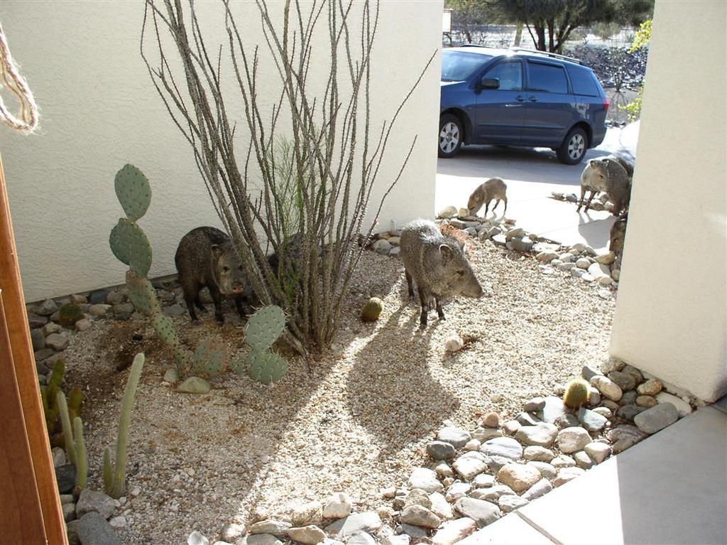
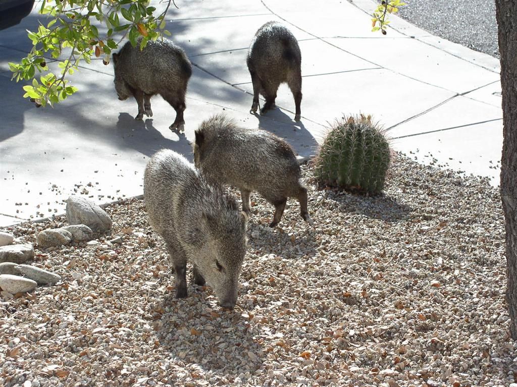
And a javelina attack!
(I hate these b*stards! They tear up your landscaping)
Still waiting on ZF parts, but I spoke with Lloyd, and they should be on their way after the long holiday season....
Reduced Bulkhead Cover Fab...


And a javelina attack!
(I hate these b*stards! They tear up your landscaping)


quote:Originally posted by Rocky:..
And a javelina attack!
(I hate these b*stards!...)
But they are so CUTE!
Chuck,
What time is the BBQ???
John
What time is the BBQ???
John
Ever eat one?
Still waiting on my ZF Parts... Talked with Lloyd (RBT) today - he's checking on my shipment. This wait is AGONIZING!
More progress on the bulkhead cover (thanks to my wonderful wife!)
Bulkhead cover cut out....
"Scrim" attached.... (See, I'm even learning some of these upholstery terms!
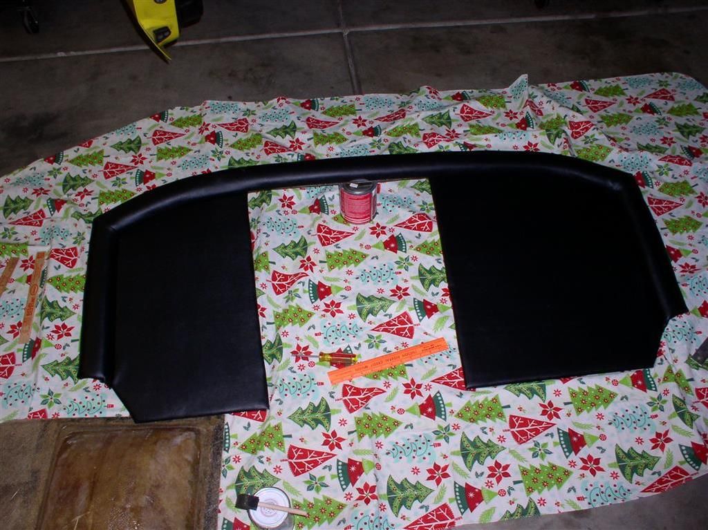
Sections are laid out.... Note that the piece on the right is the raised "rim" cover. What you see is the vinyl turned inside out - there is a lot of flip-flopping of the materials.....
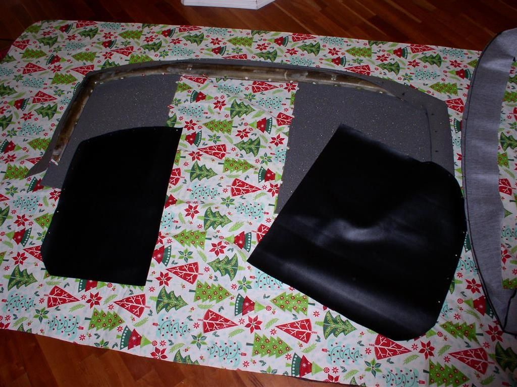
Here's close to the end product.... It's a little wavy because I have not stretched the vinyl, and glued it to the backing yet. The technique (my technique, anyway) is to install the pieces, clamp them all with the metal rim & screws, and then stretch it, and glue it to the fiberglass board.

More progress on the bulkhead cover (thanks to my wonderful wife!)
Bulkhead cover cut out....

"Scrim" attached.... (See, I'm even learning some of these upholstery terms!

Sections are laid out.... Note that the piece on the right is the raised "rim" cover. What you see is the vinyl turned inside out - there is a lot of flip-flopping of the materials.....

Here's close to the end product.... It's a little wavy because I have not stretched the vinyl, and glued it to the backing yet. The technique (my technique, anyway) is to install the pieces, clamp them all with the metal rim & screws, and then stretch it, and glue it to the fiberglass board.

Kind of proud of how my upholstery project came out!
Mounted..
Now if I could only get a silly synchro spring from RBT........
Rocky

Mounted..

Now if I could only get a silly synchro spring from RBT........
Rocky
The upholstery work looks good! can I send my dash to you?
are those round wire snap rings?
quote:Originally posted by Rocky:...
Now if I could only get a silly synchro spring from RBT...
are those round wire snap rings?
Joe, thanks for the compliment. The work took a long time, but worked out to be "relatively" inexpensive so far....
* Donor Bulkhead Panel $60
* "Scrim" and Vinyl $57
* Fiberglass Resin $15
* Fiberglass Cloth $15 est.
* Grommets $ 6
* Weldwood Cement $10
* Being Extra Nice to Wife - PRICELESS!
You will note I attempted primarily a large, flat area.
I am not really thinking I'll do the "hump" - I'm going to take it around for quotes... Hoping to do that for ~$150.... (we'll see).
Yes - Part #215 - Synchro Spring...
Attachments
Images (1)

Nice job, Mrs Rocky. Looks good.
Could the spring be a "standard" and available elsewhere?
quote:be a "standard" and available
I've searched for ZF parts, and mostly they are building automatics now (it seems) and I have not seen anything that looks right.
I did talk to Lloyd this morning, and he told me the part was on it's way. So I am hopeful.
I also hope to upgrade to a higher (lower?) ratio 5th gear (.642 vs. the current stock .704).
Scope creep continues!
Rocky
Chuck,
Let me know if you can't get the part from Lloyd.
I may be able to hook you up.
Ron
Let me know if you can't get the part from Lloyd.
I may be able to hook you up.
Ron
Thanks, Ron. It just came today.
Appreciate the support.
Appreciate the support.
Add Reply
Sign In To Reply