Another Unexpected Setback... Overcome

When I bought my car, the PO had told me about the rear bearing replacement in the uprights, and went to great lengths to describe the custom socket fabricated to do the job.

Prior to disassembly of the suspension I did a "wheel wiggle" test, and found some play in one side of the car.

Upon further investigation, it turned out the play was not in the wheel bearing, but in the bushings in the bottom of the lower upright. Here's a good thread with additional information on the bushing design:

Stubborn Suspension Bushing

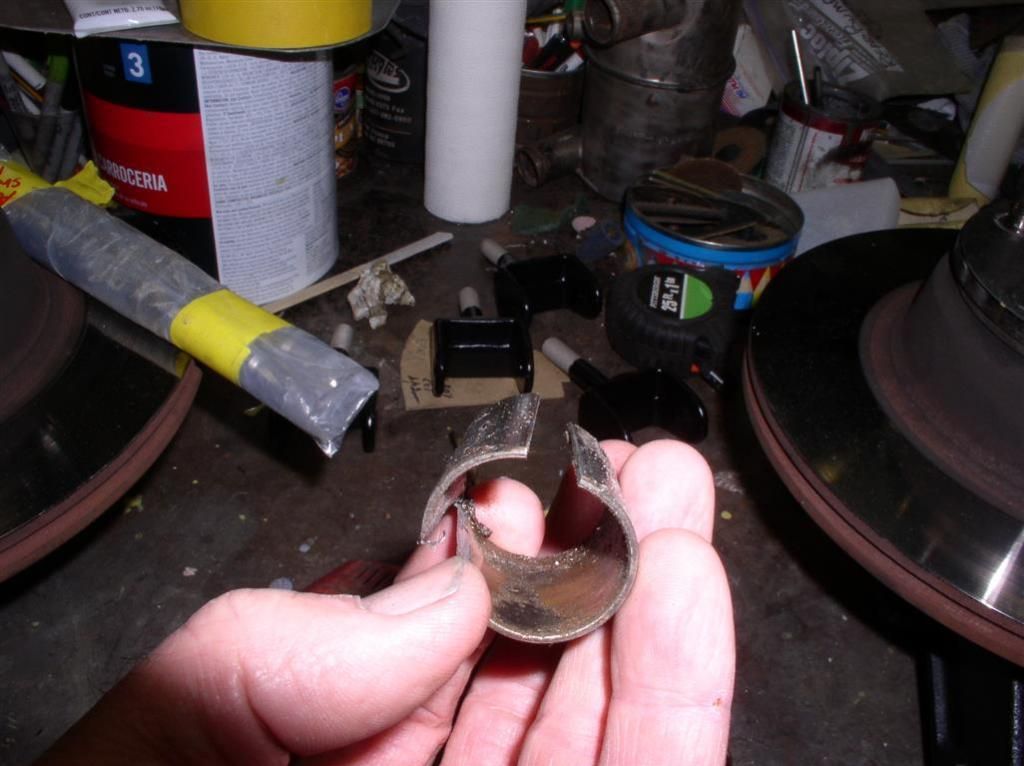
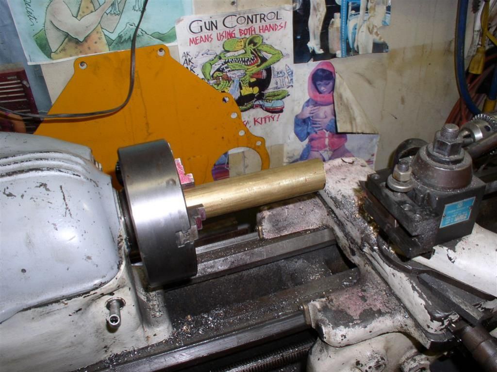
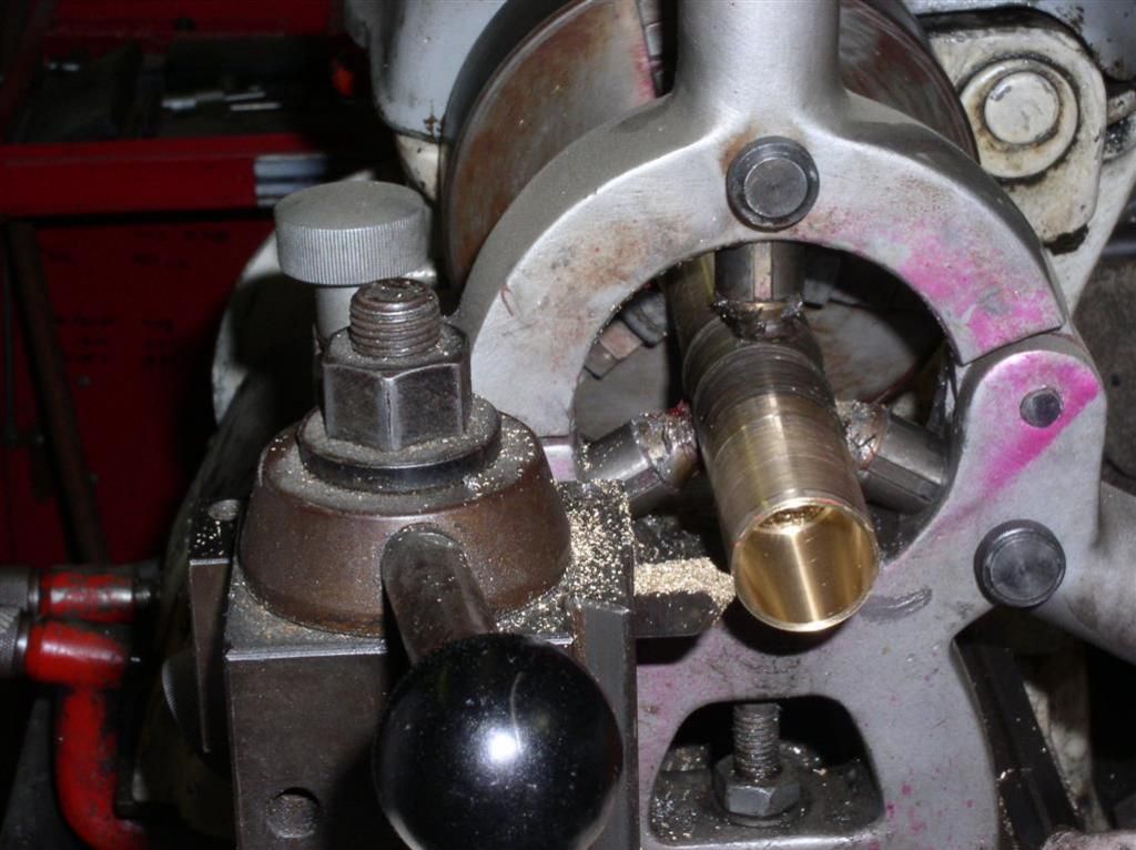
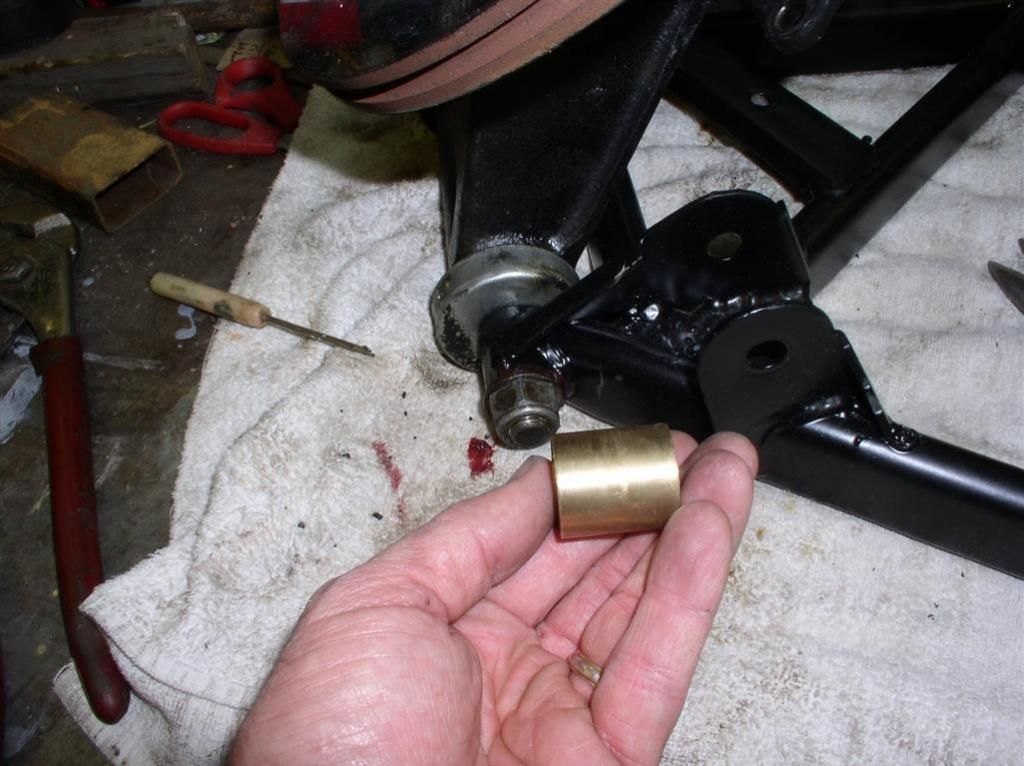
We were in a rush to get the suspension reassembled, so Wade (always up for a challenge) suggested that he fabricate the bronze bushings. The bushings are standard metric size - the id/od/length are mm dimensions 24 x 27 x 29 long.


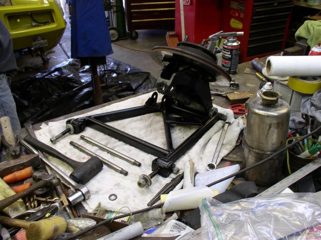
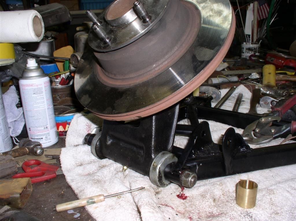
Here's a set of pictures. In the first, you can see (sort of) one of the offending bushings - it had to be cut to removed. The rest is the fabrication and assembly. Lest you be concerned, all bushings were reconstructed and replaced.

I had purchased (on a whim) two upright shafts (from Mayberry Pantera), and a complete bushing / ball joint kit (Maseratisource). All new parts were used in the reassembly.


Another major project successfully completed!

Rocky
Last edited by rocky
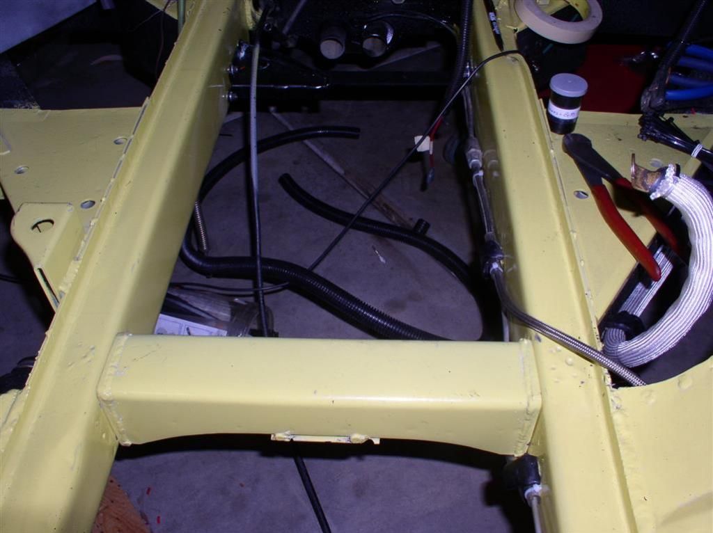
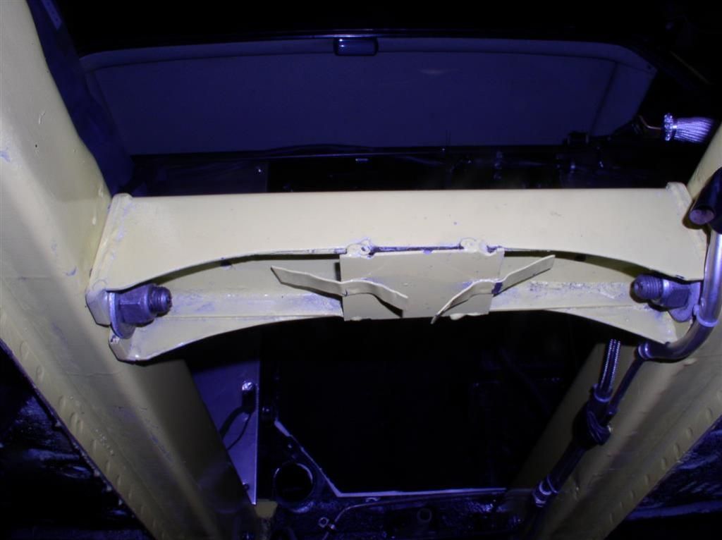
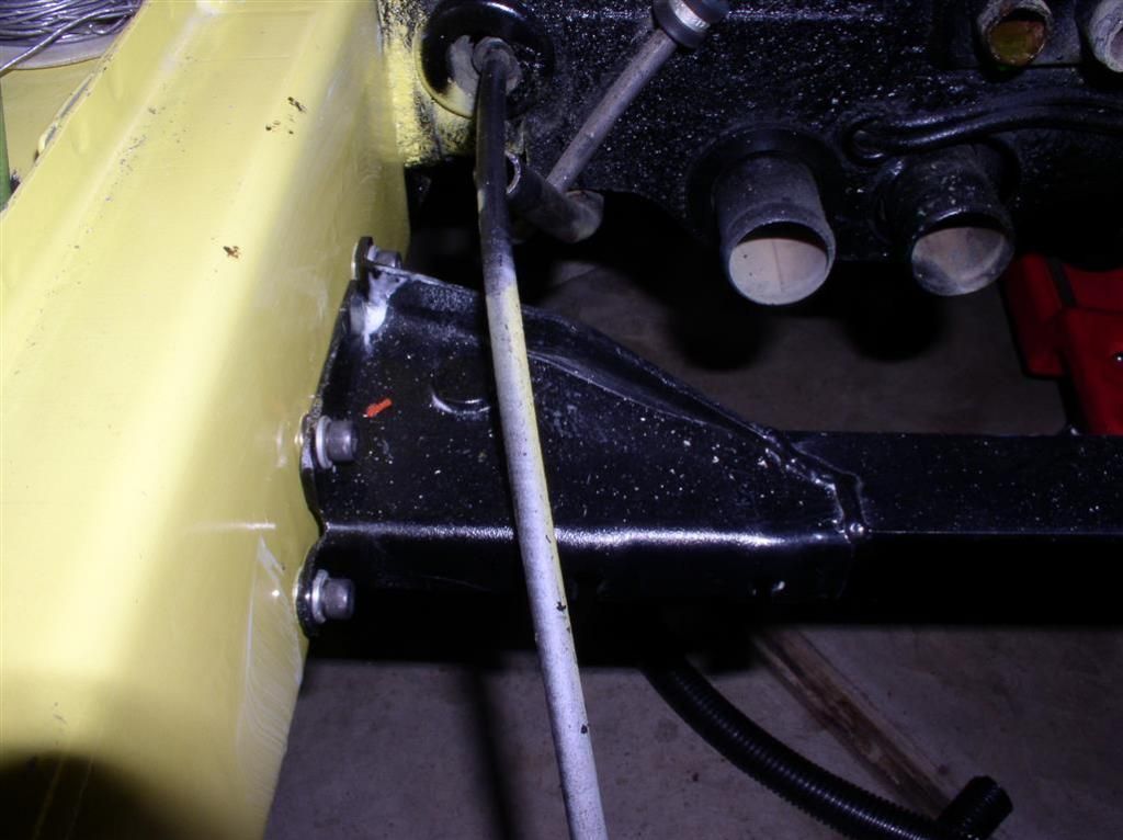
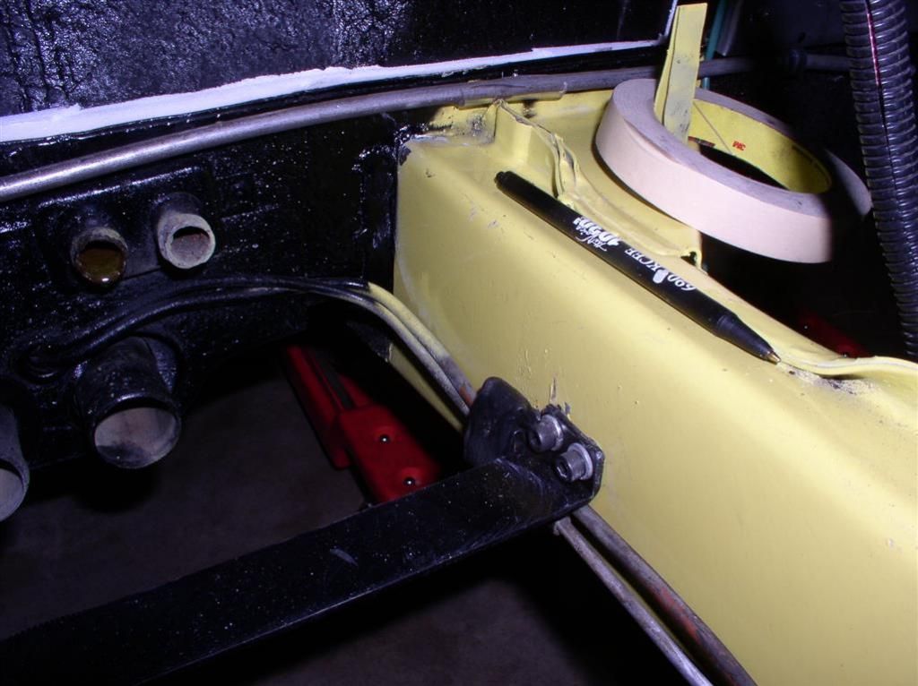
Next project -- Removable Chassis Brace and E-Brake Bracket

This one was of smaller scope.

While we were in there prepping the bay, and cutting on sheet metal, we decided it would be smart to make the bay obstructions removable.

A Sawz-All cut the bay brace, and a drill and chisel cut the e-brake bracket loose.

The Main Bay Brace required precision measurement and fabrication. These slip right in, and the brace is retained by the two forward suspension bolts.

While the e-brake bracket was of a slightly lighter construction, it required a stringer across the bay to give it more structure.

Steel Nutserts were put into the frame channel on both sides to retain things. It's plenty strong.

We chose to use the original ebrake bracket to reduce the amount of detail fabrication. All it really needed was a little more structure to hold it in vs. the force that will be applied by the lever and cable mechanism....

See for yourself. Sorry, the bay is still a little messy.

Bay Brace:


Emergency Brake


Last edited by rocky
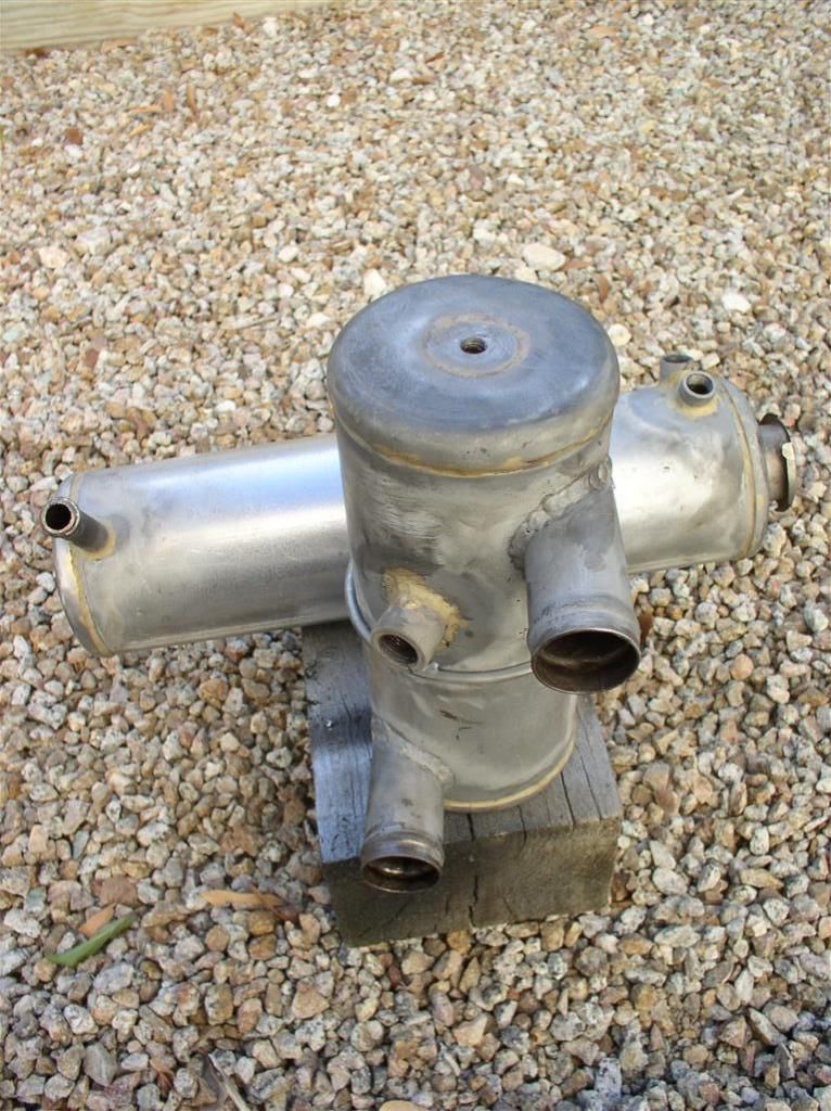
Did someone say "Cooling Tanks"?

This was more of a challenge. My tanks were shot. The swirl tank had failed in the early days of the car, and had been repaired. Cutting it open and looking inside showed it to be unserviceable. The same situation was found on the overflow tank. It was held together inside only by the big chunks of rust.

I half-heartedly looked for some used ones (which of course needed to be in pristine condition). None could be found.

In consult with a master mechanic and fabricator, we decided on an approach that would cause the system to actively draw air from the radiator and the swirl tank into the overflow, by running it at a vacuum. It looks pretty slick. I believe the design was described in one of Carroll Smith's (manager of the Shelby Racing Team) engineering designs.

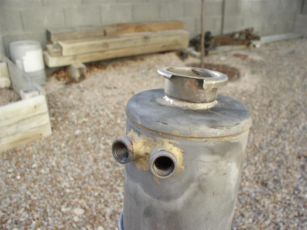
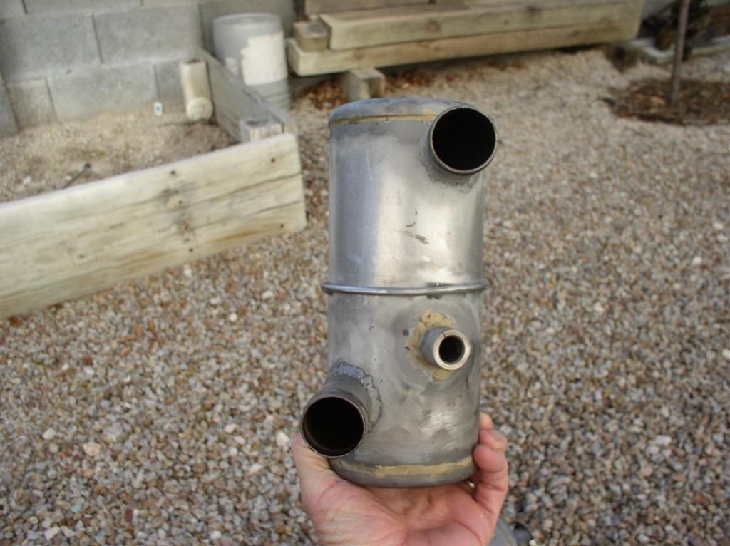
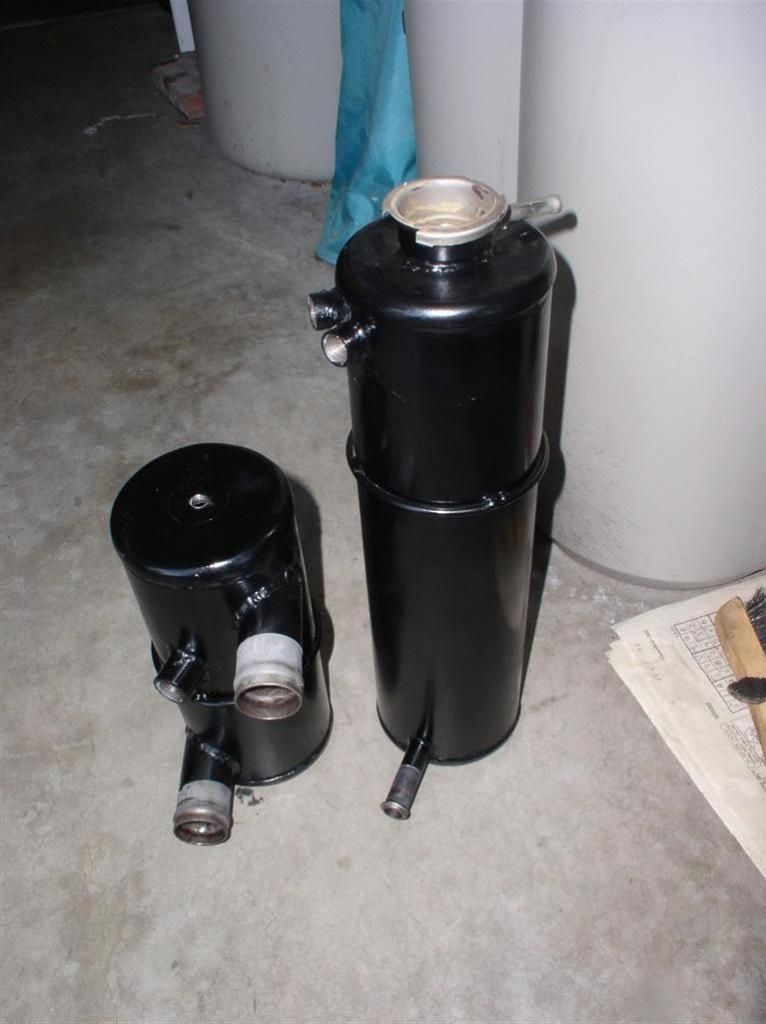
Here's the pictures. The two fittings on the tall overflow tank are the inputs (one from the top of the swirl tank, and one from the radiatior via hardline). The lower fitting is suction from the waterpump.

The overflow tank is under suction from the water pump, and will actively draw any air from the upper corner of the radiator.

The rest of the cooling system is standard, except the pressure cap has been moved to the overflow tank.

Here's what the tanks look like:


Getting tired of this yet?

More to come!
Last edited by rocky
While there is a lot more work to display, such as:

Safety Wired ZF
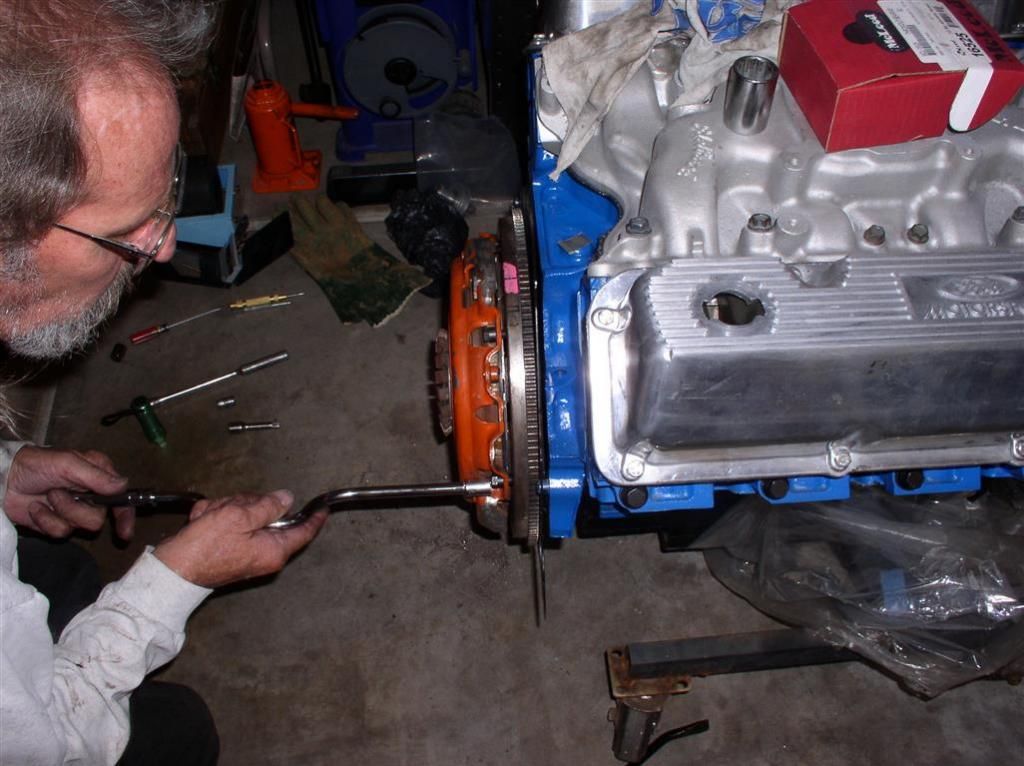
Centerforce Dual Friction Clutch
AC / Alternator Offset Mount

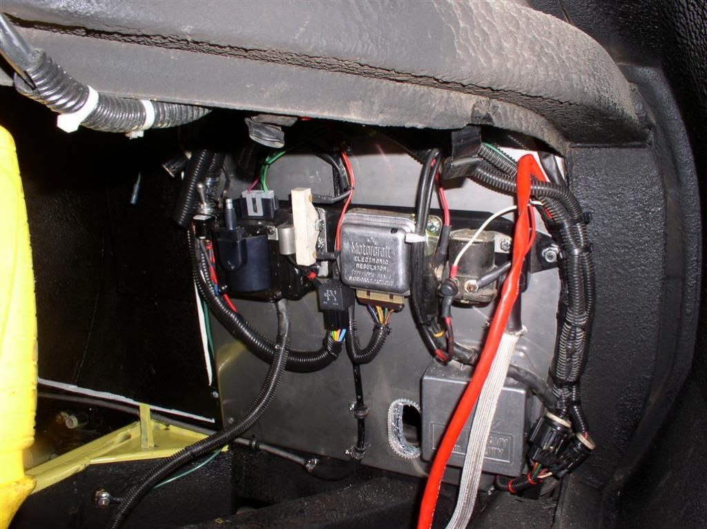
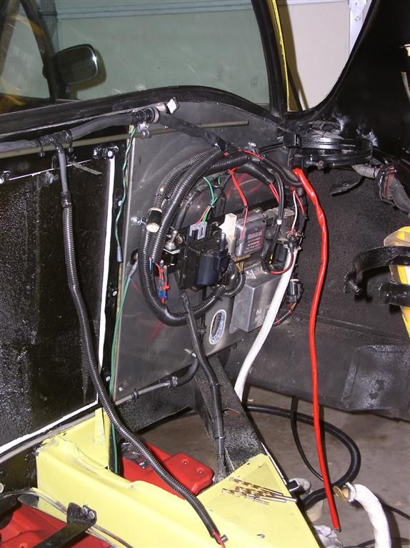
I completed with my interior bay wiring.

I had a little scare when I found that I only had 100 Ohms to ground on my alternator "main feed" with the alternator disconnected, but after some troubleshooting and test, first with low voltage, then with standard 12V, it appears that all is well.

My car has had very little electrical issues (up to now, keep fingers crossed).

I spent a lot of time dressing the harnesses. My sheathing didn't always fit as good as I would like, and I probably need a little more service loops in some area, but everything is secure.

Let me know what you think.


Last edited by rocky
Thanks, Garth -

That's a Duraspark II ignition module.

That one is a "Eichlin" (NAPA) version, but they are all about the same - from outward appearances.

Engine should be going in shortly - possibly this weekend, but if not, but the end of the week, certainly.

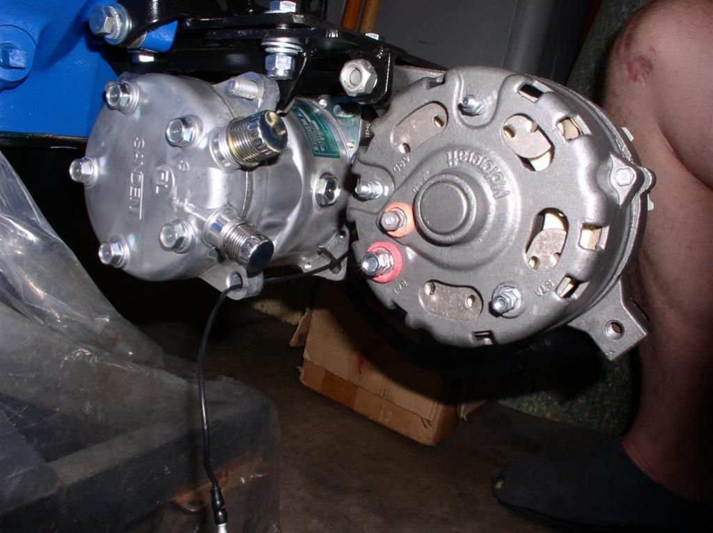
Just to whet your appetite, here's a picture of the "outboarded" Compressor / Alternator setup that Wade (4280 / Mark IV) fabbed up.... Still needs a little adjustment work on the Alternator Tensioning system (minor challenge).


Rocky

Attachments

Images (1)
  • 05-16-2014_(11)_(Small)
Minor Setback..

My cool Stewart Stage 1 351C Water Pump Impeller was jacked up (Rubbing on Timing Chain Cover) - straight out of the box!

You can see where it was touching the timing chain cover in the picture above.

Summit Racing is shipping a replacement Monday... Good customer service by them, I must say.

Rocky
You guys are very observant! The relay is the one that George recommends in his Duraspark II schematic, to reduce the current load through the ignition. Search on Duraspark II and you will find the schematic.

There is also a 15A blade fuse in there as well.

The switch is my secret ignition disable.

Don't tell anyone!

Rocky
glad others asked those questions as I was stumped about the items! (sort of guess though)

as for the "kill" switch, that is pretty well hiden as one would need a wrench set to remove firewall bump to access. I recall having a similar switch there, but it was something about setting the dual points dwell.

From the regulator, can I assume you are running the original design altenator, or is a regulator needed with updated altenators also?

And is the shown arrangement of belt driven accesories for the reduce bump firewall?
With regard to the Voltage Regulator - I am still using my Ford 1G (3 Wire) alternator. I took it to one of the local shops (Luna Industries 520.792.3080) in Tucson, and had it rebuilt. It tested at 78A output after the rebuild. The rebuild, which put better "guts" in the stock case cost $92. They replaced bearings, brushes, rotor, rectifier and field coils.

I saw no advantage (really) to converting to a 1 wire alternator, due to the inconvenience of figuring out how to rewire things. I can't remember now, but there was another issue with going to a single wire alternator - maybe it had something to do with the charge / discharge light?

The belt driven accessories are set up like that for the flat firewall cover, and the (future) flatter bulkhead. It won't be 100% flat, but enough to give my wife about 3 more inches of seat adjustment.

Rocky
You may have seen my previous thread about poking around inside of my ZF... Things inside there were worse than I thought, but it seems that I caught the problem just in time....

Am I the Luckiest Guy in the World?

Anyway -

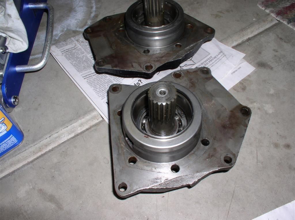
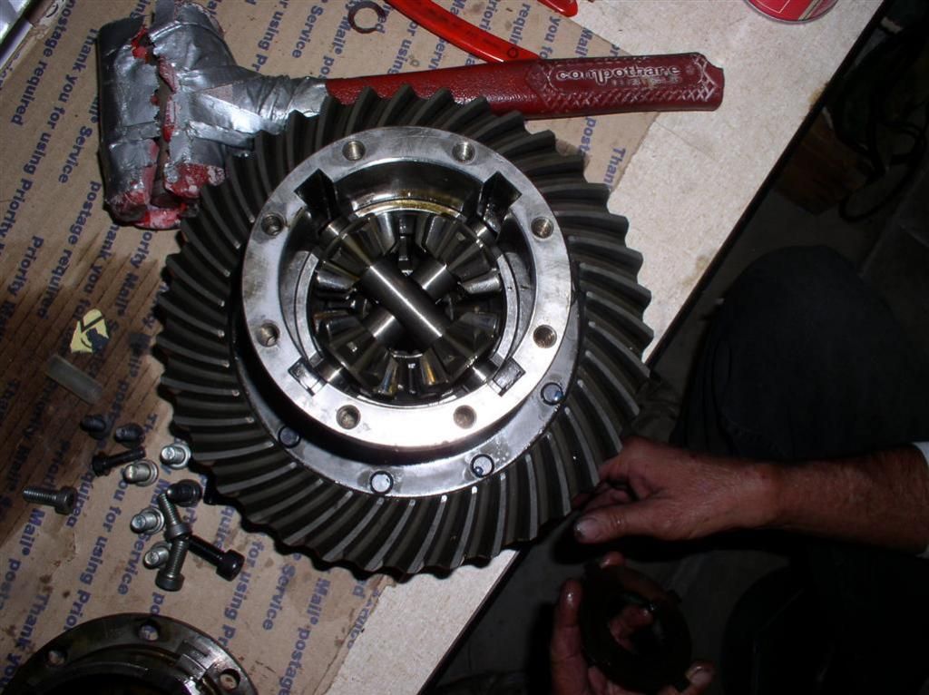
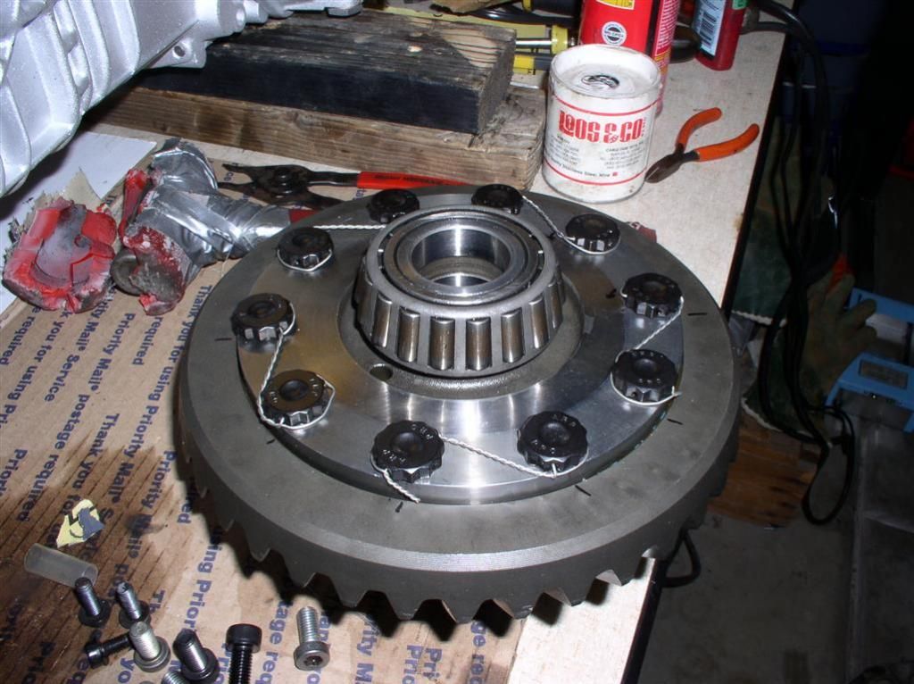
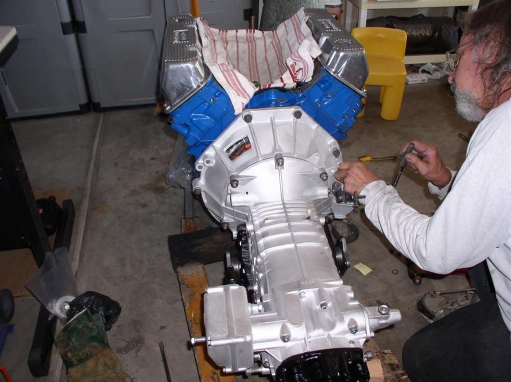
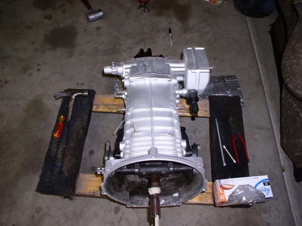
Here are the remainder of the pictures of the ZF Safety Wire project. Actually, once the ZF differential case was opened up, it was pretty straightforward. We didn't get into the gear sets.

One thing that is hard to find in one place are all the torque values. Here's a good resource - but it doesn't have them all. When you do this, you can give Lloyd, Les, Ron, or Dennis a call - they know all this stuff off the top of their heads...

Auger Resources - Pantera Information (ZF Transaxle Page)

Thanks again to Wade who gave me 1) a hand, and 2) confidence.... and I quote: "I've fixed Volkswagen Transaxles before.. Can't be all that much different than those things!"

Here's the pictures:

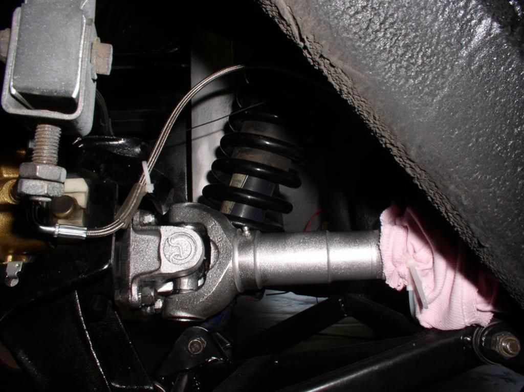
Nicely Painted Spicer Half-Shaft:


Axle Housings & Axles:


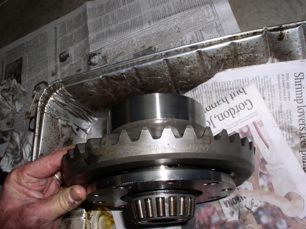
Carrier and Differential:


Note Install Date on Ring Gear: 22.12.1972


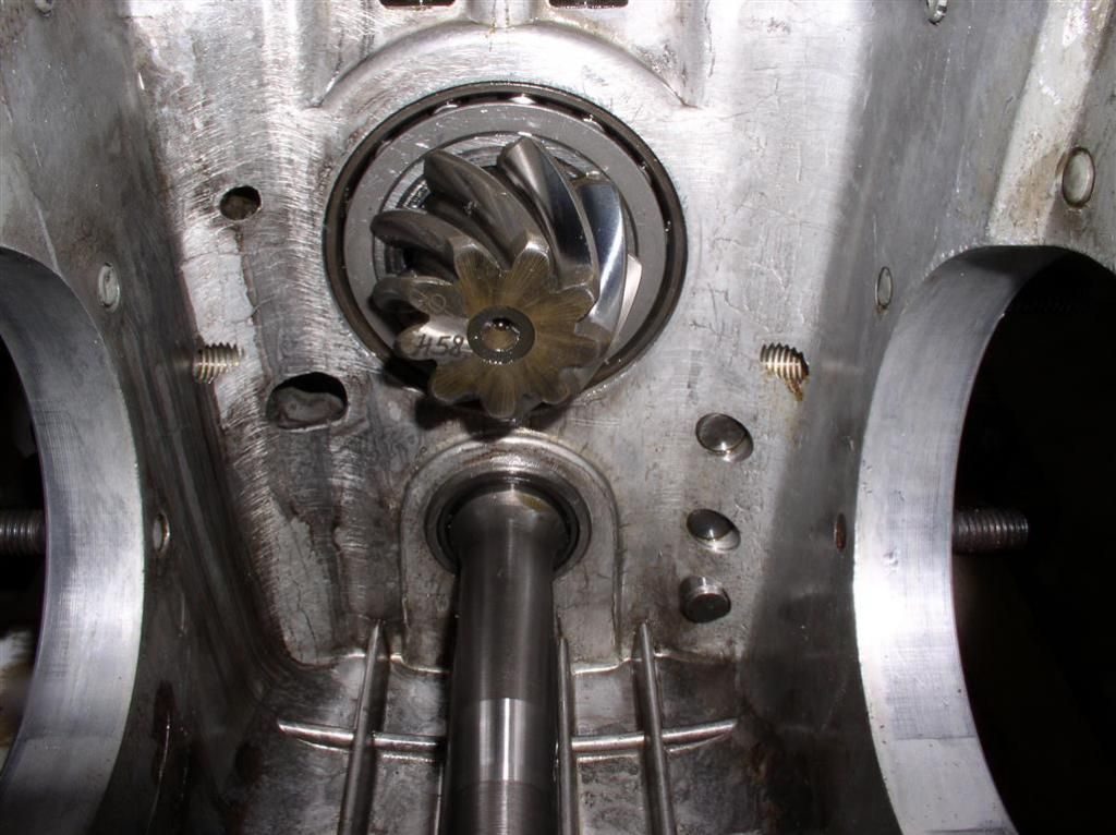
Pinion and ID Data:


Wired Up Ring Gear. Note my poor "Low Impact Hammer" in the back...


Transaxle Installed:


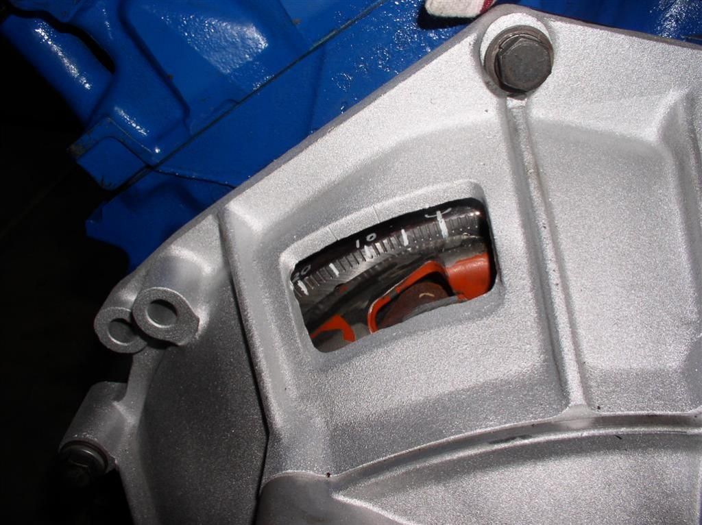
Close-Up of Degreed Flywheel:


Another MAJOR project behind me.

Rocky
Last edited by rocky
Couple of Misc. Photos to get caught up...

Still waiting on my water pump replacement from Summit. Engine is still sitting on the floor of the garage, but is almost ready to drop in.

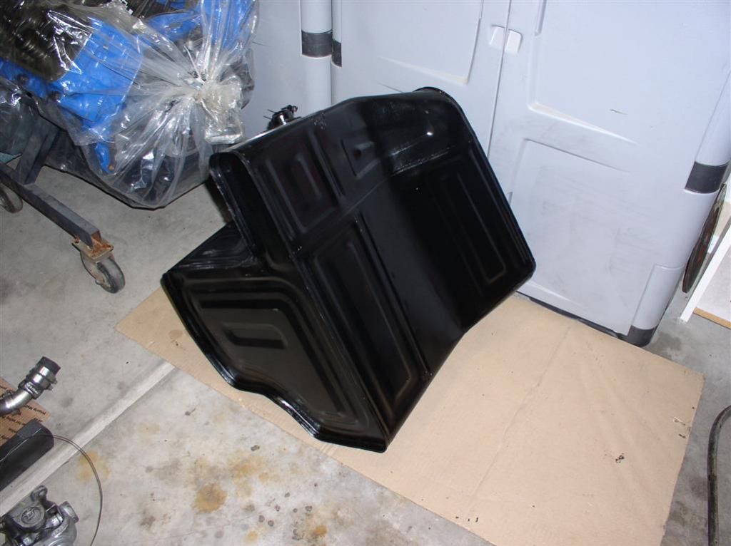
Gas Tank - Cleaned and Painted


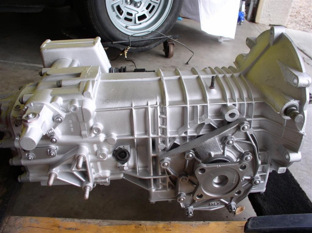
ZF - I can't stop looking at it!


Clutch Install:


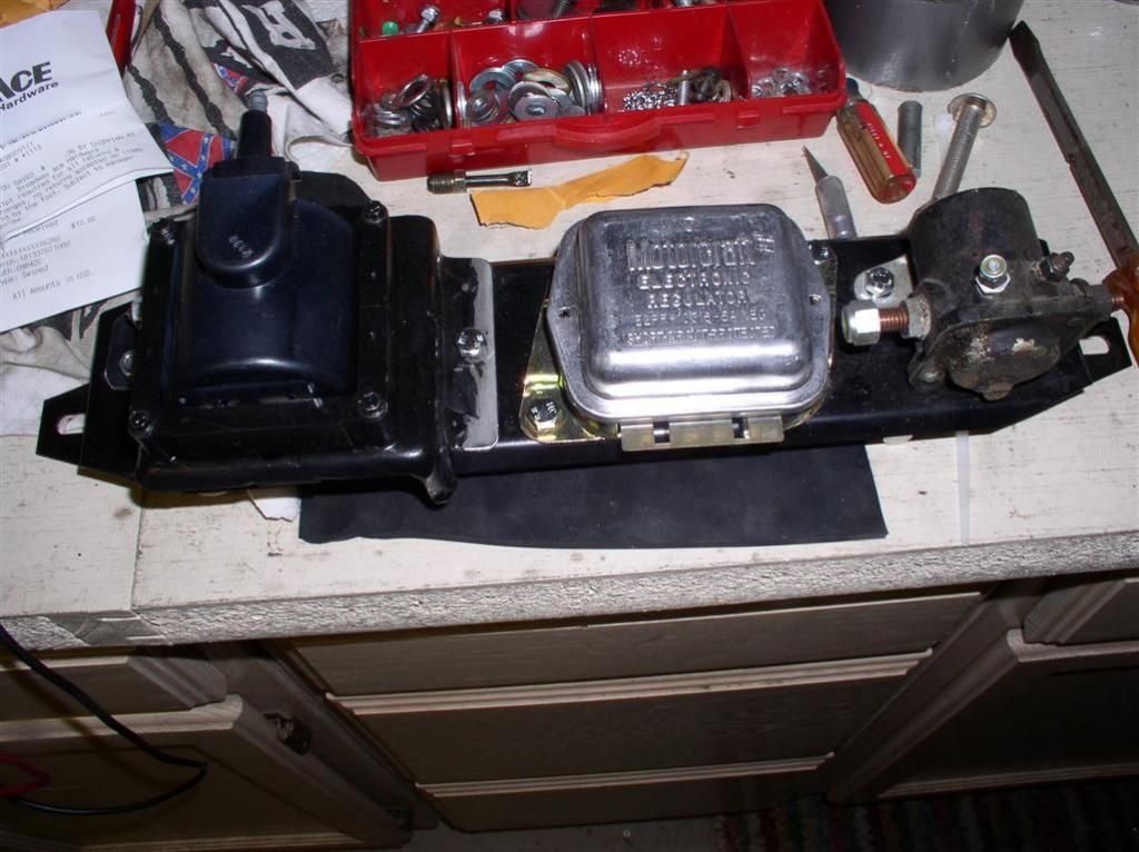
Powdercoated Electrical Panel:

Coil Bracket came from a "generic" Ford Car and was cut to fit the panel (by Wade, of course!).


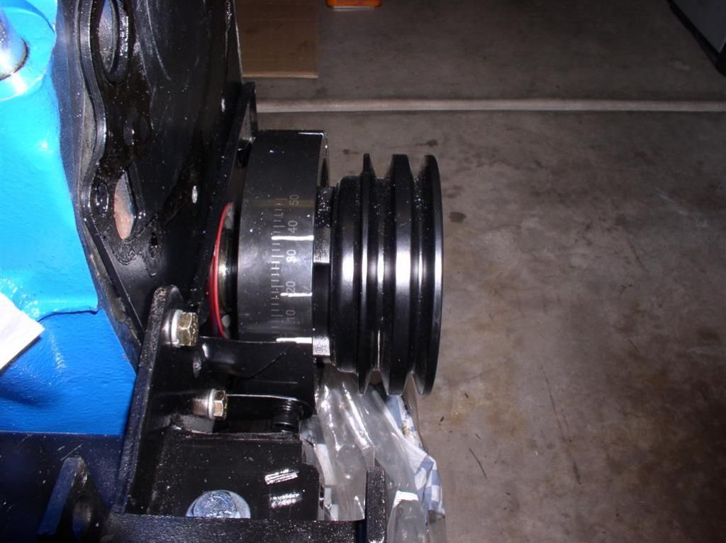
Pioneer Balancer & Powdercoated Pulley:


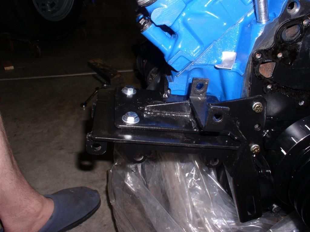
AC & Alternator Mount Adapter on Stock Bracket:


Rear View of Compressor & Alternator:


Rocky
Last edited by rocky

Add Reply

Post
×
×
×
×
Link copied to your clipboard.
×