Looks awesome Rocky! When’s the reveal?
I am hoping they shot the rest of the car today, but if not, it will be Tuesday, since it’s taking up space in the booth.
I’ll have pictures up as soon as I get them!
I’m as excited as you guys are!!
![]()
Rocky
It is taking a little longer to have pictures than I predicted above, but owners are always optimistic, and quality takes time.
The windshield was installed about a week ago, and all the trim (the black underneath) is done. It's in the final stages of paint "conditioning" and reattachment of all the "accoutrements" (handles, trim, lights, etc.)
In addition to the overall paint, I am also having the front bumper, grills, screens, and gills redone in the appropriate black color to match the bottom of the car, and my mirrors.
Great work by the Duval Body and Paint Team!
Rocky
PS. These pictures are from about a week ago.
Attachments
Looks great Rocky! Can you post or PM me the paint manufacturer and color code? Thanks!
Getting very close to delivery. All hardware painted and installed (bumpers, gills, grills, mirrors, spoiler).
A little buffing, a clean up, and she should be ready to hit the road.
Here's a couple of pictures, of both the paint, and some of the finish work on my fiberglass bumper, and new (old-school) spoiler.
I don't know if you recall (I sure do) - but some dude sold me a fiberglass bumper, and after I got it painted and tried to install it - it didn't fit. It was about 2" too short across the front of the car. Discussions with Kirk Evans indicate that fiberglass parts have a tendency to get smaller in the manufacturing process, and that there were front L bumpers circulating around that had this problem. I guess he (the seller of my bumper) forgot to mention that.
The professionals at Duval Body and Paint split and extended the bumper, and then trimmed the back of the bumper for a near-perfect fit to the front contour lines. The split is in the center - under the DeTomaso Logo.
Attachments
That looks awesome!!!
Chuck looks like you got a garage which understands good work, hard to find these days. Looks teriffic.
DO NOT MISS the windshield wipers in rainy Arizona! ![]()
Matthias
Very impressive work! Looks amazing! '
Ron
Hmmmm - I have one of those fiberglass L bumper replicas, and I noticed that it is about 2" too narrow. My car is a pre-L, so fixing and installing the later bumper is a low priority issue, but good to know others have dealt with it also.
Rod - your bumper is probably right near mine in the production sequence. Apparently the amount of "shrinkage" is related to the dimension, and so it is much more apparent in the bumper long axis than the "height" on the car.
So luckily the fitment and geometry relative to the car features doesn't change much, the bumper only needs extension.... There was precision fiberglass work needed to make the recessed emblem hole look right relative to the DeTomaso badge. We could have gone with a flat bumper, but I liked the recessed look.
The car is done - pickup tomorrow. Here's a final picture after cleanup.
Attachments
So when can I come over and check it out?
Mike Mileski
Tucson, AZ
Finished Larry's mod on the rear tail panels.
While these look more "bent" than Larry's do (and they do have about a 30* bend in them), the angle of the camera makes them look more wiggly than they are.
I made my first set of braces out of steel strap, but didn't really like how they laid in there. So I used some steel tubing. It worked out well.
Rocky
Attachments
A little bit of sad news. The Previous Owner (PO) of 5357 (Neil Dettorre) recently passed away. He really took good care of my car before handing it off to me.
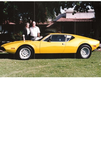
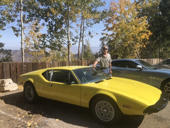
Here's a couple of pictures. First one is from the POCA Newsletter, the Oct. 2020 Issue. Thanks to POCA for the photo and the write-up.
The middle photo shows Neil and his wife Carol, in November, 1991. I believe it was down in Newport Beach or some POCA event where there was professional photography (MIAD?) associated with the event.
The bottom picture is myself and Neil at the same function - the 2016 Fun Rally in Las Vegas. We had taken a tour of the Shelby Museum and Factory.
Attachments
I just heard about Neil's Passing also! Rest in Peace. I first meet Neil and Carol Dettorre in 1993 when I first moved to Nevada! Nice People! Sad News!
I finished the install of the PE (Pantera Electronics) Headlight/Motor Controller.
While I can't say it was a "3 banana job", it took me the better part of a day to do the majority of the work. When you read the manual, it's a little off-putting, because of the number of steps, but once you dive in, the job is pretty straightforward, and the manual is clear. But it really only becomes clear once you make the commitment to do the install and you get under the dashboard!
The first part of the job was tuning up, checking, and lubricating the stock lift motors. It wasn't clear that mine had been looked at in 45 years. I took the headlamp assemblies out, removed the rear splash shields, and removed the buckets.
It was amazing the pile of screws, nuts, washers and lock washers pulled out of the front! While the POs weren't lubricating the headlight system, I think every time someone went up in there, they dropped a washer or two!
I cleaned up the area, lubricated the nylon bushings and the motor drive gear, and the "sector gear" on the headlight lift rod. As you will recall - I had already replaced the broken plastic gear with a brass one. My motor assembly plate needed a little fine tuning to engage perfectly.
I fabricated a little "sector gear stop" that mounts to the driver side radiator support (thanks, Rick), This simple bracket provides a stop for the buckets when extended, and is intended to reduce headlight shake when driving. Mine is based off this photo, but the execution is slightly different.
Once I was satisfied the stock system was OK, I jumped into the install of the PE HMC.
It's pretty straightforward - modification of the limit switches with jumpers, removing the stock headlight relay, mounting the HMC board, and wiring it up.
I made short 3" extensions from the headlight relay wires to the HMC board, it just made the hookups easier. You can see them in the last picture (below).
Next was a single sense harness (2 wires) to the stock headlight switch. Pretty straightforward, and easy routing.
Finally, a 6 wire harness to/from the passenger side fuse panel. For my own convenience, prior to the install, I had contacted Jon Haas (PE), and requested that he fabricate me the wires needed for this one, and the headlight switch harness. This eased the "prep" effort, I got wires with the correct color code, and I was able to create a very neat harness, with good routing from the drivers side relay panel to the fuse panel.
I had a minor "head-scratching" moment when the wires on the fuse panel that I was looking at didn't match the manual's drawing, but it turned out the wires needed are on the BACK of the stock fuse panel. The fuse panel needed to be removed from it's mount to access the three required wires. A quick call to PE (Jon) pointed me in the right direction, and allayed my concerns.
Once the HMC was connected, there is an extensive checkout procedure in the manual - an excellent plan to ensure that "bonehead" wiring errors won't damage any critical systems. I am proud to say, I passed the wiring test with flying colors!
Honestly - anyone can do this install. You just have to be careful, take your time, and follow the instructions.
I reinstalled the buckets, installed the headlights (new Toyota H4 Semi-Sealed Beams), and I am good to go for improved night driving!
Anyway - a couple of tips for those of you doing this install.....
Buy a bunch of the Yellow .250" wide terminals (for 10-12 AWG wire), both male & female. You use a lot of them throughout the project. You also need the Blue and Red ones as well, but not as many.
I used more terminals because of my extensions from the existing relay wires to the board, but having extensions certainly made the connections easier.
John Haas can build you the the harness from the HMC to the fuse paneI if you want. I felt like it was a good investment, and I didn't have multiple sizes of Gray, Orange and Pink wire.
Once you open things up - figure out how you want to mount the controller board on the relay plate. It goes on with only two attachment screws (For the L Model - the two lower holes), and you will need spacers. What I did was run long machine screws from the backside of the plate, and then used a jamb nut to hold the screw to the plate. Then I used two plastic spacers (they were different lengths because of a bend in the plate).
This is another one of these "Gosh, it's working fine, do I really want to do this?" type projects, but I hope it will take some load of my switches and wiring. One nice thing is the board has a lot of indicators that will help you troubleshoot it if things go wrong with the lighting.
Here's a few pictures for your enjoyment.
Attachments
Rocky,
Good writeup of the process. Nice and clean. I'm planning on installing mine this winter.
Haydude
Really great step-by-step here... saving for when I need/want to do mine because I need to replace my manual gear since it doesn't even engage and I don't want to be left with no lights at all if the electronics fail on me in the middle of the night.


