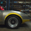
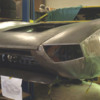
Well I know many of you purists are not going to like this.
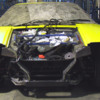
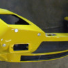
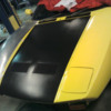
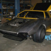
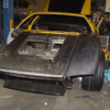
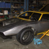
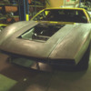
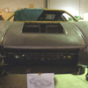
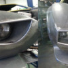
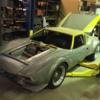
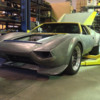
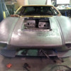
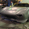
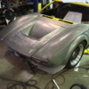
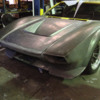
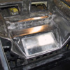
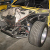
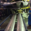
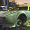
But I bit the bullet a couple of days ago & chopped off the Pantera’s nose.
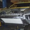
I was gutting out the front lights, radiator etc ready for new fenders to be fitted.
When I had removed most of the surplus parts I found the front of the car at some time had taken a bang & has been straightened.
This section of the car does bugger all except support the lights & radiator as well as make the car look pretty.
So it was not the fact that the car was structurally un-sound, just that with crumpled & then hammered straight steel it was a bit messy & did not meet my standard of being acceptable. (someone had covered a great deal of the creases with bog, (bondo) )
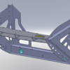
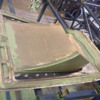
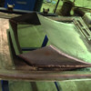
SO……….I took measurements, created a jig that supports the inner fenders from moving during cutting, (the blue structure) as well as another bolt on jig that gives a reference point for the hood hinges.
Then went onto Solidworks & created a new nose structure that supports the bodywork, integrates the hood hinges etc.
This new structure tags together like a jig saw puzzle & laser cut from 2, 3 & 4mm steel plate.
Solidworks tells me I will have a slight weight increase in the region of 4 to 5 kg.
But the alloy radiator has easily saved that amount.
Plus the new nose is a great deal stronger.
Then we cut off the old nose.
This was cut off whilst the car was up on the chassis hoist, not on its wheels which could create chassis flex.
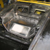
We have added a 65x35x2 RHS crossmember inbetween the the lower chassis rails as well as triangular cut RHS gussets behind this new crossmember.
Also plates to the upper rails that blank them off & give a point to weld the new nose to.
Upon cutting nothing moved at all as 95% of all of the chassis strength is from the front of the suspension arms rear wards.
I was surprised to find no rust at all within any of the structure we opened up.

The old fenders will be completley removed back to the doors & replaced with new items.

Regards,
Tony

Attachments

Images (1)
  • front_cut_copy
Original Post
Replies sorted oldest to newest

And a Solidworks picture of the new nose structure.
Should receive this in a couple of days time from the laser cutters & we will weld it up.
The green tubes you see in the lower crossmember are for access to the lower suspension arm bolts/nuts, so a socket can be passed through the hole.
The hole in the centre of this cross member will have a tube welded through & will become a towing point.
The plates where the hood hinges are located have the same curve as the hoods nose.
We will make all of the front body work on the english wheel, (with a few detail changes such as removal of the indicator pods, removal of that horizontal box that juts down below the grill & intergrate a new spoiler).
Ahhh the work I create for myself !!

regards,
Tony

Attachments

Images (1)
  • pantera_nose
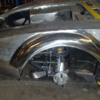
This is a photo of the previously formed fenders we made on the English wheel.
We made a buck out of steel that dropped on top of the original fender as a guide.
These fenders you can see have more of an arch over the wheel, as well as have more of a humped rounded shape as they curve back toward the hood.
Its subtle, but thats what I wanted to do, just a slight tweek on the original shape to take the flatness out of the top of the fender.
Flares have not been created yet as I have yet to finish making the wheels.
regards,
Tony.

Attachments

Images (1)
  • Front_right_side_copy
Reason for doing so?
Well it started with the previous owner’s love of bondo, (body filler).
I personally don't like the stuff being used on nice cars.
A few of the body panels have too much body filler for my liking, as well as rust starting to come through on some of the body work, (no rust in the chassis).
So I set a project to replace some of the panels with new steel items, to rid the car of its last traces of rust & to have a perfectly straight 100% steel body.
So that’s what we are doing.
We are also going slightly thicker on the panels, using 1.2mm sheet.
As I stated at the beginning of this thread, upon removing some of the components in the nose I found traces of the frontal chassis having been damaged at some stage.
So that’s why the nose structure is being replaced.
Pantera nose sections are not easy to find so creating my own seemed the most obvious solution.
At the same time I am changing the contours of the body skin a little to suit my interpretation of the Pantera’s great shape.

Yesterday we removed the doors, gutted them out, cut off the outer skins & we have sent the door frames out for sand blasting.
Once we have new door skins we will then carry on with the front fenders so we can line up the fender lines with the door line.

regards,
Tony.
Gary.
I have had my fibreglass guy make a mould for a RHD dash based on the 73' shape.
He first pulled a lightweight mould from a LHD dash.
Then made a lightweight part out of this new mould.
Cut the part into sections & cut holes in the mould to re-fit the gauge sections back in the mould, but on the opposite side.
Then glass these parts together, lift out, finish the surface of this new created plug & make a new more sturdy mould.
Very cunning as this method retains all of the critical mount points & dimensions so it will be as the original, just mirror image.
Interior wise at the moment will be focused around the RHD conversion.
We tried to make a carbon dash out of the new mould, but as it's a really deep mould its very difficult unless you go to the effort of vacuum bagging.
So I will likely end up with the original trimmed style.

LIV1S
I like your idea of the wall mount mural, that would be a great idea combined with a large background photo of the actual car.
I bet there are very few Pantera front cuts around.

regards,
Tony.

Attachments

Images (1)
  • RHD_dash_copy
quote:
Originally posted by Edge:
Damn Gary you have a lot of Gauges in there.
I love the Tacho, very simple & clear.
Tell me, what are all the small gauges?
You have provision for 9!!

regards,
Tony.


I thought that too. Actually I am missing missing one.

Dash is:
Fuel Level
O2 Gauge

Center Panel:
Oil PSI
Vac
Trans Temp
Air Ride PSI
Volts
Oil Temp
Water Temp

The small switches under the Oil and Water temp are to switch to 2 different locations to check temp.

The PSI is for the front Air shocks but I still need the tank pressure. I need to either add another gauge or use a valve to swap pressure source. I may place a hidden gauge inside the console for tank pressure.

Of course, if you look through the rear view window you also have Fuel Pressure.

Large switch on the right is a momentary toggle up/down to raise and lower front of car using the air.
quote:
Originally posted by Edge:
LIV1S
I like your idea of the wall mount mural, that would be a great idea combined with a large background photo of the actual car.
I bet there are very few Pantera front cuts around.

regards,
Tony.


You are probably right. I see more back halves than fronts. I had an opportunity once to buy a complete back half of a Pantera (from firewall, deck lid, tail, lights and all. I wanted to keep it as a spare but wanted to get some use out of it. I was tempted to louver the deck lid and make it into a barbecue but decided against the whole project Smiler
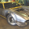
Mr. John Gilbert was busy today fitting the front left fender.
Car is sitting way to high at the moment due to a lack of parts in the nose area.
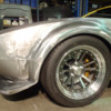
This picture gives a reasonable idea of the shape, tyre tucked in there for reference, but missing the flares.
New pedal box housing welded in on the right side for the RHD conversion.
I will keep the left side pedal box housing as a box for electrical fuses & relays.
Front tyres are 285/40ZR-17 Bridgestone Expedia.
New laser cut nose structure, (second attempt) worked out well & finally got the hood hinges in the correct position.

Regards,
Tony.

Attachments

Images (1)
  • Front_left_fender_3_copy
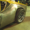
Side view
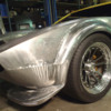
The welded join in the top of the wheel cutout will largely disapear when the flares are installed & what remains will be hammered to shape.
Here you can see how the higher fender with more of an arch to the shape flows into the shape of the door.
If you have a good look at standard Panteras you see that where the top of the fender meets the door it peaks, it does not flow smoothly.
So this is one of the slight alterations we have made to the shape as well as the increased inward curvature to the top face of the fender.
Again, the car is sitting way too high.

regards,
Tony.

Attachments

Images (1)
  • Front_left_fender_copy
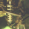
A few modifications to the front compartment.
Now has a new cross member welded in between the shock mount points.
Being that I have cut out the cross member behind the radiator this is the replacement to stiffen the front directly where the stress occurs.
Also seen here is the recessed removable Aluminium battery box.
This is about as low down as you can get in the Pantera & in an ideal position to help balance the car.
Designed to house the big 8037-327 830 CCA Optima battery.
This required a re-location of the sway bar positioned further forward to allow room for the battery box.
You can see a small round bush low down on the right of the picture.
This is a support bush for a Schroeder 26” splined sway bar.

Regards,
Tony.

Attachments

Images (1)
  • Front_compartment_copy
Tony,

Very nice work!!

Your experience that "95% of all of the chassis strength is from the front of the suspension arms rear wards" has certainly been borne out by several "Group 5" or "GTO/GTX" style race Pantera chassis.

My own race Pantera follows a similar approach - get rid of (or at least lighten) the parts not adding structural support, and re-engineer the rest to make it stronger.


I really like your subtle fender reshaping. Look forward to following your updates!

Will you also be cutting off and reworking the rear??
Big Grin

Dave
Dave, you’re correct in where the stress is.
After all it’s the wheels that impose twist into the chassis, so anything forward or aft of the suspension can aid in strength, but not very well.
Best area for bracing is at the source & between the front & rear wheels.
I have also added bolt in tube braces under the fenders that connect the nose to the shock mounts & then back to the foot pedal area. This in turn will have a bolt in section that connects back to the roll cage.
So in effect a full "bolt in" tube roll cage structure made in sections.

The rear is to receive new fenders to wrap around the new larger wheels.
Not sure yet if I will add more stiffening to the rear, but likely bolt in bar work.

Love the look of your race prepped chassis, that looks hot.

Comp2, your build & your site is very inspirational. Lots of really great ideas going on there.
My hood has a similar cut out, but because I have discarded the pop up lights & the cross tube, as well as the forward cross member I have a huge gaping hole for the hot air to exit the radiator.
This gives me lots of options in this area.

My frustration is the shear amount of time involved & progress is too slow.

Regards,
Tony.
I got into this thread late as usual. Larry Stock hit a hump-back bridge at 150 mph in his street '73 during a Silver State open road event in 2006, and BROKE both lower front subframes clear off the tub where they are factory-welded. The uppers were OK. It happened nearly at the end of the run, and a checkpoint worker paced off some 135 feet of 'air time' from the scrape marks he left past the bridge. He runs and sells an elaborate bracing system in front and back that extends some distance from the wheels and requires welding to install properly.
Larry (with a navigator-friend on board the whole time) proceeded to drive the Pantera home some 135 miles at more-or-less legal speeds. It wasn't until later the next week before he noticed some 'looseness'and put the Pantera up on a lift for a check....
I suggest not concentrating your chassis efforts just between the wheels; there are other areas that merit study for stiffening, too. IMHO, seam-welding the entire car is best, replacing all the flexy spot-welds.
Bosswrench.
That’s very interesting info.
When I mean between the wheels, that’s not just side to side but fore/aft as well.
Your right, seam welding would stiffen the car greatly.
That’s one of the things they do to most production race cars, touring cars etc when they add a cage to the car.
Modern cars are often much worse on their spot welding, or the complete lack of adequate welds. There’s so much thin sheet metal in there that’s just barely welded together. The limitations of fast modern production techniques I guess.

A question for you.
On the lower chassis rails, my car has extra stiffner plates added at the area of the bottom of the foot wells.
If you took a vertical line at the front face of the foot wells down to the chassis rails thats where the extra plates are wrapped around the chassis rails.
Like a wrap of sheet metal around the rails, maybe about 4" long down the rails themselves.
Is this original?

regards,
Tony
Slow progress.
Here the front right fender has been partially welded in place.
Still no flares yet & the car still sitting too high in the front due to lots of missing parts.
Just visible is a fabricated RHS frame in the nose which is simply a frame fabricated to line up the fenders & use as a guide for fender position measurements.
This will be removed once the fenders are fixed in place.
The right side fender is showing the slightly more pronounced curvature to the top of the fender.

Regards,
Tony.

Attachments

Images (1)
  • new_front_fenders_1_copy
A little more progress.
Front quarters & headlight surrounds being created.
There is still some work to do defining the correct line for the crease in the front corner of the fender.
As well as correct clearance around the hood & flares are yet to be created.
But you can sort of get an idea of its lines now.
The spoiler will sweep around the bottom of the fender, but will still retain that undercut swept shark chin.
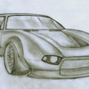
Its fairly close to my original sketch, so we are on target without any compromise.

It’s looking like a cross between a Pantera & a Mangusta, with a little of the GT40 fender bulge.
So much work to do…………….

Regards,
Tony

Attachments

Images (1)
  • Front_quarter_copy
A little more panel work.
Panels surrounding right side headlight & across the underside of the hood.
The idea now is to create a grill recess & box in all four sides feeding into the radiator opening.
The radiator clamps up against a flange with a rubber seal.
So all air that enters from the front grill area has to go through the radiator core.
I’m hoping to pick up a little more cooling efficiency via the bodywork ducting to the radiator.
It all adds up.
The 427 is going to require more cooling capacity than the 351.

Regards,
Tony.

Attachments

Images (1)
  • Radiator_surround_copy
I had looked on his FB page some time ago and unless I'm just not looking in the right place, there isnt much there. 3-4 whole car photos and a bunch of piece part photos sprinkled in with a large numebr of other pictures but not anything like a build log as near as I can tell.

I also looked on Team Pantera of Japan, lot's of good stuff there but only a couple photos Juin's car there too.

The best was the Youtube video. If especially interested in the rear diffuser, decklid, and front fender/headlight treatment. I have pinged the TP of Japan and him before but I dont speak Japanese and received no reply. If anyone has pictures of the above, posting or forwarding would be appreciayed.

http://www.youtube.com/watch?v=VzxOQ3bfdEY

Best,
K
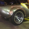
Front left flare made today.
It's about the same size as a GTS flare, but taller & more curved, as I have more wheel travel so the tyre has plenty of room.
(I have my front spring rates very soft at 225 lb so I do have a tiny bit more travel than most Pantera's).
So far the flare goes down to the body fender line crease.
Made from 1.2mm sheet with 12mm round bar forming the outer lip.
regards,
Tony.

Attachments

Images (1)
  • front_left_flare_copy
Last edited by edge
Thanks guys.
When John Gilbert does those welds he uses the Mig welder, along with an air gun.
So he spots the weld using reasonable amps to achieve good penetration.
In his other hand he has the air gun which he gives the weld a quick blast to cool it.
That stops the metal distorting from excess heat.
It’s a fairly rapid process & the results require minimal hammer work to correct.
When the panel work is finished this car is going to require next to no filler as he has achieved a very straight body with just the English wheel & hammer.

Looking forward to the new rear fenders being fitted so I can see the car sitting on its new wheels.
The rears are so massive its going to look like a "Hot Wheels" car.

Regards,
Tony.

Attachments

Images (1)
  • Front___rear_copy_1
If you go here John Gilbert has pictures on his Facebook page of a lot of the body work he has done on my Pantera.
https://www.facebook.com/media...5502897847903&type=1
He also has pictures mixed in there of my stuff like the wheels & the mechanical work, laser cut nose etc.
Also, If you start at the beginning of this thread you will see from the start with the nose being chopped off till current.
regards,
Tony.
Some more work this week.
Front corner of spoiler made & blended in with the flare.
Has an indicator built into the lower corner of the spoiler, although the intention now is to reduce the height of that lip so it’s not so deep, as well as increase the radius on the top edge.
Again the car is sitting too high as there are a lot of components missing from the front of the car.
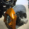
New front brakes are now installed

Regards,
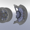
Tony.

Attachments

Images (1)
  • Front_left_spoiler_copy
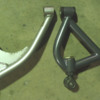
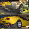
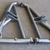
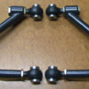
New top rear suspension arms have been fabricated.
Comparing the old with the new.
New arms are longer to stand the wheels more upright due to the negative camber change which occurs when lowering the car.
Also included is camber adjustment with a “quick turn” adjuster so camber can be fine tuned.

Regards,
Tony.

Attachments

Images (1)
  • Rear_arm_2_copy
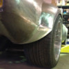
New left rear fender being fitted.
Lower section of the fender is still not attached & has not yet had the body line crease created.
Wheel arch is simply hacked out at the moment to get the wheel on.
At the moment I’m trying to get the ride height correct so we can make the wheel flare to suit.
A lot of material around the wheel arch will have to be removed as the flares will be quite large.
(This is the 345/35-19 Bridgestone tyre)

Regards,
Tony.

Attachments

Images (1)
  • Rear_left_fender_copy
Tony,

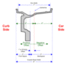
I'm a bit confused. A 9.5" wide rim with centre (zero) offset could not have 4.75" backspacing. A 9.5" rim with zero offset would have 5.25" backspacing. Conversely, a 9.5" wheel with 4.75" backspacing would have .50" negative offset.

As far as I know, all wheel manufacturers calculate offset and backspacing the same way as pictured in the diagram below.

Attachments

Images (1)
  • offset
One tiny note on David Nunn's excellent drawing: not all wheels have the outboard 'bump' for wheel weights or whatever on the extreme edge of the rim, so technically, the backspace should go from the flat part of the wheel to axle flange rather than including the bumps. Sure, all Campys have them, but aftermarkets, steel etc vary all over the map as to the heights of bumps or whether they're there at all. Thats also why some people get 4-3/16" for 8" Campy backspace while others get 4". Just a thought for consistency.
quote:
One tiny note on David Nunn's excellent drawing: not all wheels have the outboard 'bump' for wheel weights or whatever on the extreme edge of the rim, so technically, the backspace should go from the flat part of the wheel to axle flange rather than including the bumps. Sure, all Campys have them, but aftermarkets, steel etc vary all over the map as to the heights of bumps or whether they're there at all. Thats also why some people get 4-3/16" for 8" Campy backspace while others get 4". Just a thought for consistency.


Excellent point. My aftermarket rims don't have that extra lip. So instead of an extra 1/2 on each side like the drawing, mine have approximately 1/4 extra on each side. So my 9 inch rims measure 9.5 inches from the outside to the outside portion of the rim. They measure 9 inches where the tire seats.

My rear 12 inch rims measure 12.5 from the outside lip to the outside lip.
quote:
Excellent point. My aftermarket rims don't have that extra lip. So instead of an extra 1/2 on each side like the drawing, mine have approximately 1/4 extra on each side. So my 9 inch rims measure 9.5 inches from the outside to the outside portion of the rim. They measure 9 inches where the tire seats.

My rear 12 inch rims measure 12.5 from the outside lip to the outside lip.


This is exactly why most high-end wheel manufacturers nearly always refer to offset as opposed to backspacing. With offset, the thickness of the outer "lip" doesn't effect the measurement. You would typically only have a half-inch thick outer lip with a cast alloy wheel.
My front rims are centre offset.
I take the measurements from the important part of the rim, the bead area.
What is outside of the bead face is of no consequence & varies greatly between pressed steel, cast alloy or spun rims.

Kirk, I’m in Perth Western Australia.
Yes it would be great to catch up.

Regards,
Tony.
To David's point, if we don't use a consistent way to measure the offset or backspace, the data is useless or misleading. Offset may be a better number since the lip type doesn't matter...

Thanks for all the info, I wasn't sure how to measure rim width and offset/backspace until this topic came up.
Larry.
So that extra plate that can be seen in my original arm is not "original" & possibly modified?
With my huge 345/35-19 tyres I needed to lower the car alot to get the stance right.
So I made my new top arms a little longer to dial out some of the excessive negative camber & included the adjustment for fine tuning.
regards,
Tony.
Tony, most Panteras' upper rear subframes tend to spread and distort over time, developing excess negative camber. Huge, sticky rear tires tend to make this situation worse, even cracking paint on the rear fenders. The stock bay brace is almost useless in preventing all this since, along with the upper front ball joint mounts, one simply cannot tighten the bolts tight enough to prevent bumps from making the bolts move.

With a good aftermarket (or home-made) adjustable upper bay brace, the rear chassis can be preloaded enough, slowly over time, to tease the rear subframes back into stock alignment. This makes longer upper rear a-arms redundent, although most I've seen appear stronger than stock. And at least they're better than some early efforts to 'correct' excess rear camber by lathe-cutting the lower a-arm clevis-ends so the lower a-arms were pulled inward more.... while weakening the attach points to the frame.
Good points Bosswrench.
I love hearing the history of Pantera issues, cures & modifications.
My negative camber issue is the top arm going past horizontal.
This is due to lowering the car so much due to the large wheel diameter.
As the car lowers the top arm arcs inward & progressively throws the rear into negative camber.
Here is a picture of my engine bay brace.
The rear attachments connect to the old bumper mounts.
Although I’m going to have to gut out the engine bay for the new engine, which gives me the opportunity to reinforce these areas & add bar work as required.
Regards,
Tony.

Attachments

Images (1)
  • Cooling_system_copy
More slow progress.
Front hood being made.
A curved piece of 20x20 RHS has been tack welded across the Hood to help keep its shape whilst the rolled edge for the radiator ducting is being formed.
The front edge of the ducting has yet to be formed.
The hood has been made from scratch with internal pressed bracing that mimics the original Detomaso factory part.
Side rockers have also been cut off ready for rolling new items.
Regards,
Tony.

Attachments

Images (1)
  • Front_Hood_2_post
The new hood has been receiving more attention.
The internal panels that form the radiator duct are being formed.
Here they can be seen tack welded in place.
A jig needs to be made to make sure right & left sides of the duct are welded in symmetrical.
Panels have to be removed, trimmed to size, slightly re-shaped before being finally welded in place.
Regards,
Tony.

Attachments

Images (1)
  • front_hood_duct_1_copy
Kjeld.
The distance is around 350mm.
But it is to be ducted as well with a shroud that fits with a rubber seal against the back face of the radiator.
And the hood opening will seal against the top edge of this shroud.
The shroud will contain two fans.
So the shroud becomes an adaptor between the radiator & hood.
It is designed so the radiator seals with rubber against the front of the bodywork.
So all the air that enters the grill must go through the radiator, then through the shroud & up out of the hood.
The air flow through all of these parts flows very clean with no obstructions.
regards,
Tony.
Kjeld.
I sent you the laser cutting file for the weld on Pantera nose didn't I ?
Yes, both the bib spoiler & the shroud/hood will produce down-force.
I also plan to install little wing shaped aluminium louvers where the shroud joins the hood.
This will act as a grill & block out vision of the fans & radiator so our law enforcement idiots cannot see the radiator.
(some stupid law they have regarding fluid getting on your windscreen from rear facing holes in the hood).
regards,
Tony.
Thanks Rob.
I like the look of the lights without the covers.
That dark eyed hooded recessed look, a little like the mustang.
The headlight bucket has a vent to prevent air pressure build up which will likely be vented to the brakes.
The idea of the car has always been performance & function first, & if we can give it a tough elegant stance at the same time then that's a bonus.
regards,
Tony.
Nice metalwork and a lot of it! The only known reason for pop-up headlights in any car are the old headlight-height laws some areas specified for unknown reasons. They seem to have mostly gone away.

The GT-40-look hood exhaust requires cutting the front section of the front trunk away, and that part is a structural part of the Pantera's front monococque, so I suggest some sort of bracing should be added back. I put an aluminum angle-iron crossmember between the lower frame rails behind the steering rack, and it not only stiffened up the front structure, its what my dropped battery sits on with no battery box needed.
This is the crossmember added between the shock mount area.
You can also see the recessed battery box which is a bolt in alloy item.
The panel work has been re-plated around the box to stiffen that area.
The new nose structure which is welded into the chassis is also a thicker material.
regards,
Tony.

Attachments

Images (1)
  • Front_compartment_1_copy
You can see here, when the nose was first cut off a section of RHS added between the very front mount point of the lower suspension arm.
This RHS also gives a sturdy area for the new nose to weld to.
You can also see wing plates added forward of the upper suspension arm mount point.
These plates not only tied in some of the flappy panel work to the upper chassis rails, but gave the mounting point for the bolt in bar work, (shown above) & again a weld point for the new nose.
regards,
Tony.

Attachments

Images (1)
  • Front_left_fender_removed_copy
Interesting you mention the sills, (rockers).
The reason I took the car off the road in the first place was to do some panel work to the left side sill.
Someone had jacked up the car, let it down too quick & crunched the sill.
That exposed layers of bog, (Bondo) which made me see red!
Hate bog in nice cars.
The silly thing is, we have replaced just about every panel on the car except for the roof skin.....................and the sills.
The very reason the car was taken off the road was those sills. And although we have cut them off, new ones are still yet to be made.
I'm fitting a 38x2.6 CDS tube the length of the sill, which will be tucked up inside & welded into the chassis before the sill goes on.
Tied into this tube will be pickup plates where the main rollbar hoop & rollcage sections bolt in.
So all bolt in rollcage tubes tie in together, but some are hidden away & become part of the structure.
regards,
Tony.
Your sheet metal work is fantastic. Love it.

I can't help but compare the addition chassis tubing to what Hall did with "Purple passion", the t-top car.

I suppose when it comes down to it, there are only a few places to put it though in the spaces that are available to the car?

One thought I had was that if the original sheet metal in the outer/inner rockers, i.e.,"pontoons" itself could have been made of a thicker steel, then it could eliminate the need for the tubing?

I thought about what you did also, BW, with the aluminum L's but shouldn't that have been steel?

All of this "investigation" is really just showing me the flexibility of the front of the "monococque".

The first time I saw the front of the GT40 chassis with the nose up, it scared the heck out of me.

It was essentially just made up of 1" square, 1/8" wall tubing with very suspicious looking welds.

I think much like the original Pantera, when you design it for 6-7" wide rims with 185 profile tires it doesn't bring out the weaknesses to the design.

When you start to squeeze 285-30 profile tires on 10" wide rims, all the monsters start coming out of the closets?

It just makes me think, why not just cut the entire front chassis off of the car and build a complete bird cage for it? Where does this stop?


Now if you are thinking to yourself I wish Doug really would stop this thinking business, you aren't the first one to come to that conclusion.

I had a Professor threaten to duct tape me shut and put me in the corner facing the wall.
Also, I debate things with myself as well so don't feel singled out. It gets really ungly when I grab myself by the throat and beat my head against the wall.

At least the pain from that keeps me from thinking for a while but the pain starts me moaning from the discomforts? Go figure?
Doug, most of my mods are of the 'looks OK- lets try it' type. I had a length of 1-1/2" x 3/16" aluminum L and a need for a dropped battery support. The piece is so short (less than 12" I think) the material is unimportant, given its multifunction. And I LIKE light-alloy! A suspension cross-brace probably should be between the upper frame stubs, not the lowers but I had also discarded Bill Stropp's rack-brace when I did the factory-type bump-steer mod. So I thought I ought to attempt a little stiffening in the vicinity.

As far as 'flexible fronts', Larry Stock's SS Pantera once hit a hump-backed bridge at 150+ mph and flew nearly 140 ft during an event. On landing, the entire lower front frame assembly cracked off the areas where it was factory-welded to the tub. Had he not had a welded-on chassis bracing system, things might not have turned out so good. As it was, Larry and his navigator picked up their trophy and drove the '73 200 miles back to Carson City without noticing the front frame extensions had broken free. Surprisingly, the much heavier rear area was unaffected & held its alignment specs. Too bad I couldn't mention this to Carroll Smith who thought the main problem with Pantera 'racers' would be in the rear assembly.
When most are speaking of these radical modifications whether it be sheet metal or just chassis, there is no point in doing this just for the jollies.

I would think if serious racing was involved as in Larry's car, I think there is significant evidence that the original monococque chassis is being over challenged?

I have always wondered what the difference between courage and stupidity is? It would be very stupid for me to go 200mph in this car.
Most of the items I have made for my Pantera I have designed on Solidworks.
Such as the rollbar, suspension arms, font nose module, remote thermostat, 930 CV upgrade, Taper roller bearing rear upright upgrade, wheel rims etc.
If the part was structural I have conducted FEA on the part, (Finite element analysis).
Such as the nose & suspension arms & wheels.
To a certain extent there is a bit of educated guesswork involved to determine how much stress the part actually sees in the real world.
But if nothing else the program shows where the main stress areas are, the weak points.
And that means you have a better idea of where strength or stiffness is required.
It's a good tool to aid in design & removes the hit & miss approach.
regards,
Tony.

Attachments

Images (1)
  • 17_cutaway_forum
Last edited by edge

Add Reply

Post
×
×
×
×
Link copied to your clipboard.
×