Hi everyone,

Need a bit of assistance from all you great Pantera experts answering so many difficult questions. Btw - thanks for always being so helpful to all in here. :-)

Now to my question - where I need help. 

I got a Pantera 1974, mostly stock, very few modifications (done from before I bought it), only real big difference is engine has been rebuilded and added MSD box. Again done before I bought it. 

I've got the problem the temperature gauge is always at "zero" or better said, at lowest possible indication. It always stays there no matter, if engine is just started or after 1 hour of driving, still "zero". 

Now my question is, what the best sequence to debug this problem?

Or perhaps some one knows what's the typical problem is in such a case?

Any help is very much appreciated. :-)

Cheers

Chris

Last edited by George P
Original Post

Replies sorted oldest to newest

The Ford temp sending unit is prone to failure. 45 years of age is a LONG life for a $6 sender. That's the first thing I'd try. Note that the sender should be in the block just below the thermostat, NOT in the surge tank. That was an early attempt by Ford/DeTomaso to fix high temp readings that scared drivers with the early 0-220F gauge. Next was a 6 watt resistor twisted, not soldered, into the rear wiring loom. They come loose from vibration. Third was a non-soldered 10-watt resistor, and finally, no resistor at all and a 0-260F gauge (with a resistor built inside) in 1973.

So your '74 car's 0-260F gauge should not have any external resistors for reasonably accurate readings, but it's worth checking. I've seen resistors crack. If it's actually the gauge, most vendors stock replacements. Fixing a stock gauge will cost at least as much as a new gauge.

If you are just troubleshooting to see if the problem is in the gauge or the sender...

Pull the wire off the sender and connect a 50 Ohm (or 30, or 20, or 100 Ohm, whatever is easy to find) resistor via a wire with alligator clips to a good ground in the car.

Your gauge (if working) will swing to full scale (or close to it).

Go from there.  It's a pretty simple - low resistance = higher temperatures.

Good Luck -

Rocky

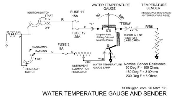
PS>  Data from SOBill, at Pantera Place.

Resistor_Temp_Guage


Attachments

Images (1)
  • Resistor_Temp_Guage

Hi everyone, 

Spend some time last night measuring continuity, the wires going from the gauge to the sensor (at least the one, I think is being used) is fine. The wires works, there's connection.  Also it seems the wires are connected correctly on the back side of the temperature gauge.

I've taken a few pictures, and will add a link to the picture here in the post. 

http://tinyurl.com/yxjxhlbd

It puzzles me from the pictures, why the sensor seems to have been move to a coolant pipe....don't believe it's correct location for it. Please let me know if I'm wrong?

Also one of the wires on the sensor, I would have though should be pink (power), but it seems it's a full RED instead. Don't know if that's stock for a Pantera from 1974?

 Above one asked my if the gauge ever worked in my ownership, and the answer is no. Don't recall it ever worked.

 Haven't tried the latest ideas mentioned, but will do tomorrow. Initial one will be the resistor replacement, that sounded like a very good idea. Then I'll try the other good ideas as well. 

 Finally, just want to remember to mention a VERY BIG thanks to all helping me, really impressive, I surely appreciate it. :-)

Last edited by George P

Me thinks I have a very good idea what your problem is.

You say you’ve traced wires and they go to the temperature sensor that has two wires.

 Whether it is an idiot gauge temperature sensor or the variable temperature sensor used on the Pantera, a 70’s Ford sensor has just one wire.

 The other electrical connection is provided through the engine block. 

An idiot light sensor is just a switch that closes at a preset temperature, turning on your hot coolant light.

The Pantera gauge sensor is a actually a variable resistor,  controlling the voltage to the gauge and thus the movement of the needle. 

 I suspect you have an idiot gauge sensor and the extra wire is the ground? 

 The factory installed the sensor, incorrectly, in the surge tank where if you lost a lot of coolant the sensor would be surrounded by air not coolant.   

 Proper location for the sensor is in the face of the engine block just below the thermostat. 

Buy a proper sensor for a gauge, not an idiot light equipped, 1972 mustang. Put it where it belongs and hook up the signal wire to it.D5731510-7218-485B-8917-E1B1BABEC763

I imagine you will then have a functional gauge.

Larry 


Attachments

Images (1)
  • D5731510-7218-485B-8917-E1B1BABEC763
Last edited by lf-tp2511
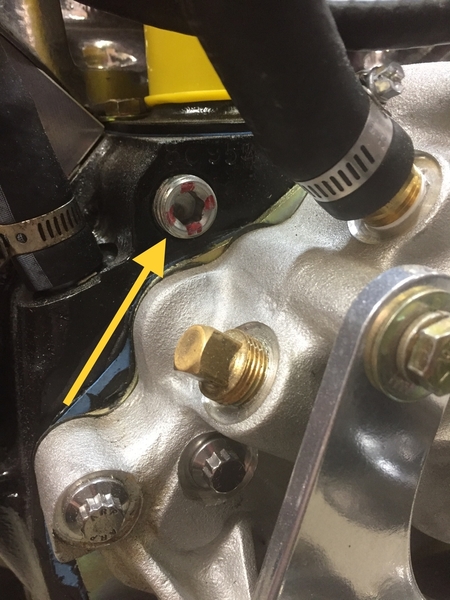
BTW, the place on the engine block the sensor should go (where millions of Mustangs have it) will have a 1/4" pipe plug in the hole. Remove the plug and install the sensor, then use the factory plug to stop up wherever the sensor was. Threads should be the same.
Second note: use one turn of teflon plumber's tape on the pipe threads. If you use too much teflon tape, the sensor will certainly not leak but also may be electrically insulated from ground. That may in fact be why your current setup doesn't work. Good luck- J DeRyke

🤔🤔 Had to Google the vacuum switch that George mentioned and it looks like he is correct. Having never had a stock Cleveland in 2511 the photos didn’t ring any bells for me.

Granted, it shouldn’t be connected to the temperature gauge but if he has followed the wires to it then maybe it is, in fact, the problem? 

 I think Chris needs to do some more discovery research. 

 And take pictures and share them with us. 

Larry

Chris, Looks like some funny wiring has been done on your car which sadly is the norm after 45 years.

the SOBill Wiring diagram shows a red with black stripe wire going to the temperature sensor.

One of your photos shows a red with black stripe wire connected to your device but it has a non-factory terminal.

 I also think I see a red with black stripe wire at the gauge.  

 I suggest you get a long jumper wire and test continuity to determine if the red with black stripe wire at both locations is in fact the same wire. 

 If you find that to be the case then follow my previous advice, buy the proper sensor, mount it where it belongs  and attach the red with black stripe wire.

That could make your temperature gauge functional.

But I have no idea what you should do with the vacuum device shown in your photos  

Larry

If you want advice from a recliner want to be mechanic ;

Ignition OFF

Locate water temperature sender

  • Front of block under thermostat
  • Mid way down on the coolant tank

Disconnect single red with black strip wire from sender

Measure resistance of wire back to gauge, 100 to 200 ohms

Switch ignition ON

Measure voltage of wire from gauge, 4 to 8 volts

With wire disconnected, gauge should be full cold

Using jumper from good ground to wire and gauge should go full hot

If not, problem with gauge

Use jumper from wire to temperature sender outer hex, gauge should go full hot.

If not, installed sender is not connected to ground.

If so, replace sender.  

trouble shooting sender . . . . . (to be continued)

But suggest testing new sender before installing by measuring resistance cold and boiling water.

WATERTEMPERATUREGAUGEANDSENDER_000001

Attachments

Images (1)
  • WATERTEMPERATUREGAUGEANDSENDER_000001
Last edited by George P

Hi all :-)


Followed up on all your good advises and have take more pictures and added to the folder in the link:

http://tinyurl.com/yxjxhlbd


Dismantled the seats, firewall and got access to the front of the engine. 

Searched for the temp sensor in the engine block, and found it, not wire on it. Hence either the previous owner disabled it, either because it didn't work or else because he wanted a different solution. I'm leaning toward that....due to the sensor the RED/BLK wire is attached to. (some called it vacuum sensor yesterday). I don't know if it a "vacuum sensor", not even sure I know what such a thing is....but on my car this sensor is place in the middle of a big metal pipe going directly to the water pumo, hence I do beleive it was suppose to work as a temp sensor - at least my guess. 

Anyway - I did a resistance meassurement on the temp sensor in the engine block, and the resistance was 373Ohm at a temperature of 22 degress Celcius (71,5 degress Fahrheit). To me that sounds to little, I would have though it should be higher - but if anyone out there know right resistance for the sensor at 22 degress Celcius, I would love to know it. Because it if its not working right, I gotta replace it, if I want to re-wire to this temp sensor, instead of the strange solution being called a vacuum sensor. 

Then I continued to do testing of the Temp gauge. I toke the RED/BLK wire from the Temp gauge and placed a resistor between that wire and ground. The results can be see from the pictures in the folder. But to my knowledge it seems the temp gauge works just fine. If anyone looks at the pictures, and mean differently, I would love to hear about it. 

So this is how far I got today, based on all your help and good ideas/advises... :-)

a) Would really love to hear from anyone who can tell me how I figure out if the existing temp sensor in the engine block is working as it should? or perhaps how to test it extensively. 

b) Also would also like to hear if you all as I, believe the temp gauge works correctly, because then that can be disregarded as a source of failure.

c) Finally, I'm still puzzled about this called "vacuum sensor", was there ever place a sensor in the big metal pipe going to the water pump? or have the previous owner of my car have had he small weird projects and created something peculiar?


As always, thanks for all your interest and help :-)

Cheers

Chris


Hi Chris -

You can do an easy check on the temperature gauge on the block by:

1.  Looking at, and understanding the graph I posted.

2.  Taking your ohm meter and measuring the resistance from the center conductor of the original temp guage and the engine or a good solid ground.  With the engine cold, it will be higher than 160 ohms.

  • That's the first test.

3.  Then start your engine, and either drive your car, or let it idle until you think the engine is warmed up.  Then measure the resistance of the temp sender.  If you have a thermal IR gun, you can find the temperature of the swirl tank, or the engine block right next to the gauge, and it SHOULD match the solid purple line.

  • That would tell you if the sender is working as it should.


If it is:  Then hook the ground line on your gauge to the vehicle's solid ground.  Then hook up the "(+)" wire on the guage to your temp sensor.


Rocky


Chris, the schematic posted by Joe (JFB05177) provided temperature sender ohmage for three temperatures. Its in the lower right corner. 90 degrees F = 100 ohms, etc.

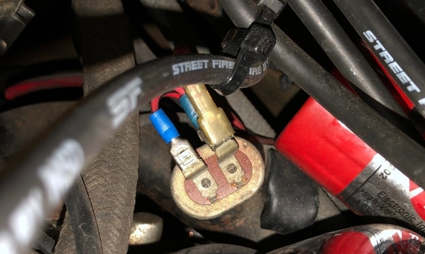
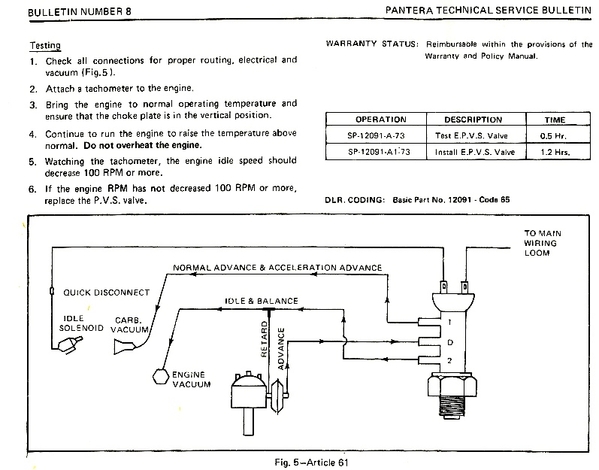
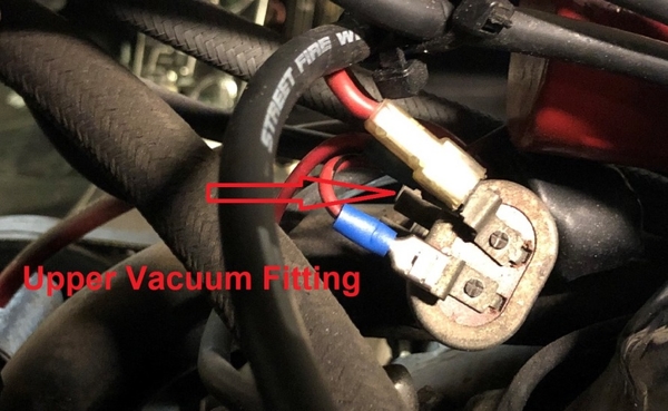
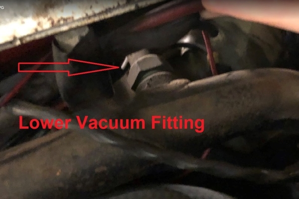
Here's the Ford documentation regarding the electric ported vacuum switch. Please note that it has 3 vacuum fittings, plus 2 electric terminals. The EPVS incorporates a switch to interrupt power to the idle solenoid, plus it manipulates the vacuum to the distributor advance mechanism. The overall purpose of the EPVS is to reduce engine idle speed by 100 rpm upon rising temperature.

Since it is actuated by rising temperature it had to be screwed into the coolant system in order to "sense" temperature.

epvs-schem

In the first picture below you can see the upper vacuum fitting, nothing attached to it.

epvs-1

In the second picture you can see the lower vacuum fitting, nothing attached to it. It is safe to say the vacuum controls of this switch have been disabled.

epvs-2

"Senders" provide a variable resistance in order to modulate the current flowing through gauges. As Larry (LF-TP2511) pointed-out previously "senders" only have one electrical connection, their other connection relies upon being grounded by whatever they happened to be attached to.

The EPVS however has two connections … because it is a switch, not a sender. True it senses temperature, a necessity of a temperature switch, but it has no provision to provide a variable resistance. 

Coolant pumps are engine driven. Does it make sense to reduce engine speed, and pump less coolant, when an engine over heats? Of course not. The EPVS did more harm than good, so my advice is to always disable it. 

EPVS

Attachments

Images (4)
  • epvs-schem
  • epvs-1
  • epvs-2
  • EPVS
Last edited by George P

Add Reply

Post
×
×
×
×
Link copied to your clipboard.
×