Does anyone have experience torquing the rear axle nuts to 400lbs using a torque multiplier tool? I already own the special socket. I wish to back the car onto ramps, remove the half shafts and use this tool to torque the nuts.
Thanks, Blake.


Does anyone have experience torquing the rear axle nuts to 400lbs using a torque multiplier tool? I already own the special socket. I wish to back the car onto ramps, remove the half shafts and use this tool to torque the nuts.
Thanks, Blake.
Replies sorted oldest to newest
The multiplier will need something solid to react against, and the wheel's going to want to rotate. Careful up on the ramps. 400 ft/lbs at the wheel, something's likely to move.
There's other ways...
Thanks for the reply.
Wheel chocks on front wheels, strap the rear wheel to the ramps with compression straps.....who know what else....lower the tire pressure. All to avoid taking everything apart😁.
Let you know what happens. I have read about a gear driven torque multiplier. Maybe my Snap-On buddy can give me some insight.
I always use a high torque air gun, 150 psi and just let it hammer away until it doesn't move anymore, you can actually here when it is tight by the tone of the air gun.
I have done this with everything assembled on the car but it is not easy. The available arc of travel for your socket handle is minimal and requires patience, but can be done.
As for the torque multiplier I have never used one but I do believe it is appropriate for this operation.
Larry
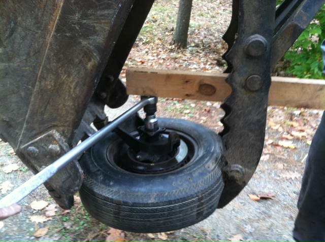
Yea, this is a sucker to do. I didn't have access to a torque multiplier so I had to do it with a 4 foot pipe on a 1/2" breaker bar.
I made a 1/2" thick plate that went over the wheel studs and welded an arm to it, then did it on the car using the car lug studs to hold it in place, the bar turning against the floor.
That is so much leverage that you need to be careful you don't pick the car up off of the floor when you stand on the pipe.
I think I tried it on the workbench like in the above picture but I tore the vise loose from the top it being only 3/4" plywood. I figured on the car was "safer". (Yea, that's the term...safer)
For the weld, you need to go back to your "strength of materials" class and calculate the size of the weld needed with an e60 electrode. It's pretty big and the "stick welder" was on like 150 amps.
I calculated that if I stood on the "arm" being 220 pounds that at 36" when the nut wouldn't turn anymore, it would be about right.
I'm not sure that you can do it accurately with an impact gun at 150 psi air pressure? I was more comfortable with my method, and I don't know if I was "fortunate" not to break a leg or arm, but I got it done.
You do need to be concerned with over stressing the gun, the air hoses AND the compressor itself.
Don't forget that the "impact gun" IS going to "kick" when you hit it with full tank and that you can shatter the gear in the gun. I didn't want to take that kind of a chance. I don't do this every day.
The issue is that there is little procedure for accurately measuring the applied torque without the multiplier.
To this day, I still don't think there are any local shops I could rent or borrow a torque multiplier from?
Maybe the "semi" shops have one but none of the big "semi" guys will even talk to me to this day. They suddenly become mute.
They get like $500 an hour with the "vehicle" on the lift in the shop and helping you takes "food out of their kids mouths".
Caution should prevail. Use the black impact wrench sockets, extensions and components. You don't want even a Craftsman forged socket suddenly shattering on you and throwing shrapnel in your direction. This ain't for "kids" to do. You can get killed doing this.
As I recall, I MIGHT have broken the pin on the 1/2" breaker bar on one, then bent the pipe too? I'm not sure? I prefer not to think about that. Gives me chills thinking about how freakin' crazy I really am? Next I'll be catching bullets in cotton padding? Well, maybe not?
You can twist yourself up really good with doing this too? My chiropractor wants to know exactly WTF I do, being so twisted? I think she means my back but I'm not completely sure that's what SHE meant? Maybe that's why people are afraid of me? Hum?
I have found a multiplier that Snap-On makes. The small unit will do up to approx 650lbs. It has a 1/2 inch input with a 3/4 inch output. I should be able to use my standard 1/2 inch torque wrench set at max. Hopefully I can borrow one from my Snap-On buddy.
i also located a more heavy duty unit at my local rental shop that goes up to 1000lbs. - United Rentals.
Thanks for the replies and photos. Always leaning new things with the Pantera😊.
How much is the rental?
Not sure. They were closed yesterday(Sunday). I will post when I find out.
have you checked with brand name car parts stores
they loan tools for free
don't know if multiplier is one they would have
thinking,. . .
doing it on the car (or any where else) do you have a way to push and hold the socket HARD on tthe nut?
Second person pushing?
That was not an issue for me. The clearance difference (.008") between the socket and the nut kind of locks it in place within reason.
COMMERCIAL tool rentals here do not have torque multipliers. Forget about chain parts stores.
The best bet is to watch ebay for a good used one. They come up occasionally as the big trucks need them just for the lug nuts alone.
marlinjack posted:…A 4 Foot Bar with 100 Pounds on the End will give you 400 Ft/Lbs.
With the Assembly Mounted ON THE VEHICLE; I torqued the Nuts until they would Not Tighten Any Further.
Had a Helper hold the Brakes, and had the Tire on the Floor, with the Full Weight of the Car, to hold from turning. Tighten Beyond the Brake Slipping and the Tire Slips on the Floor, repeat as Necessary. As Tight as You can get it, will be More than 400 Ft/Lbs.
REMEMBER! The Drivers' (On American Cars) LEFT side Nut has the LEFT-Hand Thread!! 'Mass at Rest 'Tends' to Stay at Rest!'
...Last, You are NOT to Re-Use, the Original Nuts! They must be New.
Marlin
Well sure, but it depends on where you stand on the bar. You need room for two feet and be positioned so you don't hit yourself in the private parts. ![]()
I said this isn't easy and it's a wonder I didn't kill or mame myself right?
Also, YOU CAN'T just hold the assembly on two lug studs, you will snap, shear those suckers right off. The studs, not your privates...but . Best to make a plate and use all 5.
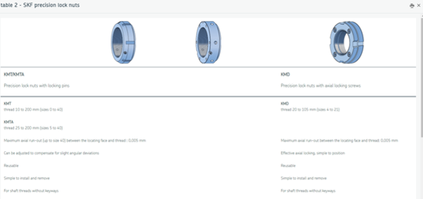
By machining a groove in the shaft and using a SKF nut and a tab lock washer, it becomes unnecessary to tighten to 400 ft.lb, the nut can no longer loosen
It isn’t often one sees an entirely new solution to a Pantera problem, but this one is certainly new to me.
Thank you very much for sharing. Studying the photographs clearly shows how this was accomplished.
Would you happen to have a part number or source for the lock washer you used ?
👍👍
Larry
As well as the P/N for the SKF nut, if it's unique as well. Thanks.
Rocky
René cool as ever!
we need the Part Numbers for SKF and the nice washer!
(i have not done it, but if needed happy to see you in the Perigord!!)
mercy!
matthias
As I do not have a milling machine, I made the groove by hand with a grinder .......... it is not very beautiful
the references are KM7 and MB 7:
https://www.skf.com/group/prod...ts/keyway#cid-465338
https://www.skf.com/us/search-...ite=327&q=MB%207
matg posted:René cool as ever!
we need the Part Numbers for SKF and the nice washer!
(i have not done it, but if needed happy to see you in the Perigord!!)
mercy!
matthias
When you want and with pleasure in the Perigord
René, thank you for this priceless information.
Do you have the reference number for the left hand thread also?
Can't seem so find it on the SKF site.
The torque number is to load the bearings, not necessarily to keep the nut tight. You can do that with Lok-tite.
If you aren't torking to 400 then the bearings aren't loaded correctly.
It's the factory's number, not something out of the blue or from outer space. Modify it at your own risk.
panteradoug posted:The torque number is to load the bearings, not necessarily to keep the nut tight. You can do that with Lok-tite.
If you aren't torking to 400 then the bearings aren't loaded correctly.
It's the factory's number, not something out of the blue or from outer space. Modify it at your own risk.
Preload is only justified with tapered roller or possibly angular contact bearings, not with simple ball or deep groove bearings.
At least, it was like that when I was studying in an engineering school in the early 70s, when the Pantera were produced.
brickdrifter posted:René, thank you for this priceless information.
Do you have the reference number for the left hand thread also?
Can't seem so find it on the SKF site.
I did not find it at SKF and bought it from Hall Pantera, but the locking washer can be used with.
rene4406 posted:panteradoug posted:The torque number is to load the bearings, not necessarily to keep the nut tight. You can do that with Lok-tite.
If you aren't torking to 400 then the bearings aren't loaded correctly.
It's the factory's number, not something out of the blue or from outer space. Modify it at your own risk.
Preload is only justified with tapered roller or possibly angular contact bearings, not with simple ball or deep groove bearings.
At least, it was like that when I was studying in an engineering school in the early 70s, when the Pantera were produced.
I agree, I would expect a torque rating like that to be used with tapered bearings. I don't know where 400lb-ft is required at all UNLESS the consideration (a paranoid one maybe) was that the designer wanted the bearings and the spacer for all intents and purposes to act as a single machined piece and he had previous experience maybe from Formula 1 that a torque like this was the safest bet?
I don't like that much torque particularly considering that the axle hardness to begin with is questionable (shown to be too soft and not hardened adequately by the original manufacturer) and worry that maybe I'm stressing out the threads and stretching the axle by going to that much torque?
Still, I am not Giancarlo Dilara. If he tells me to jump, my only question is how high?
I like your creative thinking on your modification but am concerned for 1) the crushability/durability of that lock washer and 2) something I'm missing that Dilara knows and I don't.
How much torque are you going to use with your modification? 400 I think is ridiculous to begin with? How can you calculate a preload with the modification? If I knew why it was 400 to begin with then maybe an educated guess would be in order?
Formula 1 cars of the era were only about 450hp and weighed around 600kg (1320lbs). Maybe the Pantera rear uprights are a common F1 design of the time?
A lot of experienced designers use an empirical method. They use what they know works. If it breaks, make it thicker/stronger, then if it doesn't break, they give it to a mathematician to write a predictable formula for it. Does that sound like Dilara? I don't know?
Oh...I give you high credit and kudos for the courage but I stand by my original comment of "modify at your own risk", because of all of the above. ^. No offense intended
Do you really think that Dallara calculated all the assemblies, that would surprise me. At the time there were far fewer engineers than today and many sub-assemblies were designed by less qualified people, especially in a small company like De Tomaso. So I'm not sure it was an engineer who was responsible for the rear hubs.
Dallara has certainly calculated the chassis himself and we all know that it is not a model of rigidity, as what even the engineers of formula 1 may not always be skilful.
I think a torque of about 150 lb.ft is more than enough.
I have no idea how he would have worked.
I know as me being a "junior structural engineer", nothing I did got done without a two step oversight of approval.
In the '70s, "modelling" was being used. It was before computers and still the age of slide rules.
As I said, I don't know where 400lb-ft comes from or is necessary to begin with. I will add that the rear upright of the Pantera resembles that of the Ford GT. That one being cast in magnesium though.
Was that modelling? Why reinvent the wheel. Take one off the shelf and plug it in.
I think the issue with stiffness of the "chassis" is just an under estimate of horsepower and tire gripping capabilities using 1968 standards.
The Mustangs, Cobras and GT40s all show similar indications of lacking here and there. Race cars were stiffened with roll bars and cages AND NO manufacturer (including Ferrari ) provided for their cars to still be around over 7 years. That number is still used and proven by the actuaries the makers use.
150 sounds like a guess? Got the formula? ![]()
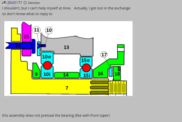
I shouldn't, but I can't help myself at time. Actually, I got lost in the exchange so don't know what to reply to
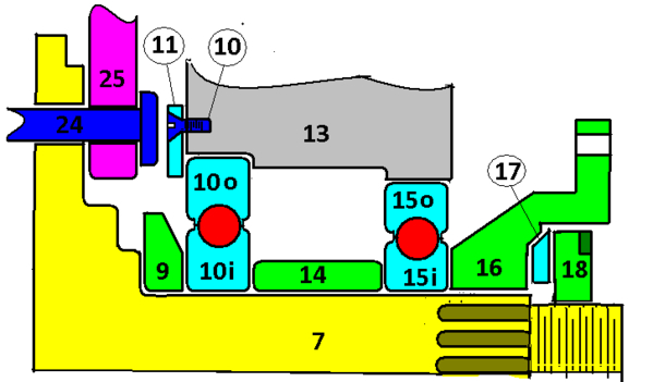
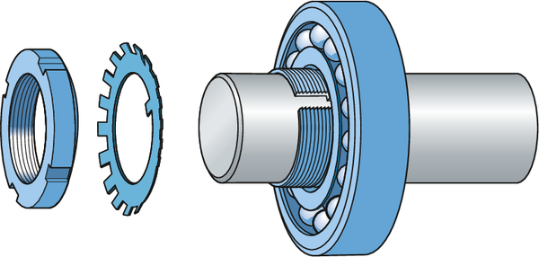
this assembly does not preload the bearing (like with front taper)
the nut is to make the inner two races (10&15) one with the axle (7)
the threads are a 1 3/8" bolt thus a "normal" torque for a cheap bolt would be ver 400 ft-lbs. (almost 3X)
In my previous life (back when I knew how too) Verify bolt torques use to be one item I had to calc. the reduce outer diameter of the locknut versus a normal bolt head will reduce to required torque somewhat. (I just don't fell like calculating anymore)
the locking washer (installed between 17&18) would have no compression, thus a solid washer as the outer tabs are outside the nut face.
Tired now and going to take a knap!
edit. . couldn't sleep
a quick run through a MathCad routine I used for land base turbine bolting
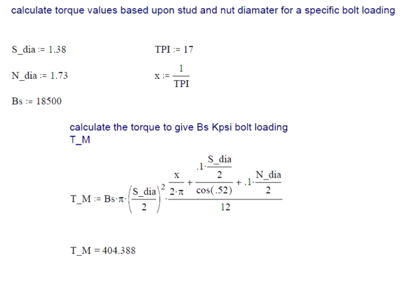
I played around with the Bolt Strenght value to see what the threads would be loaded to at 400 ft-lbs. Note a cheap bolt would have a strenght of 60kpi.


jfb05177 posted:Tired now and going to take a knap!
LOL! Me too! Calculating gives me a headache. Nappy time!
I doubt if any even cares, but I had an epiphany!
looking at the data sheet for the lock nut
https://www.skf.com/group/prod...way/productid-KM%207
It states an axial static loading, (but not specified as recomended nor maximum) of 50 KNextons (11,240 lbf)
using the known area of the threaded section, the Kpsi tension loading caused my tighten the nut is easily found
Then with that Kpsi, the torque can be calculated with the equation I used above.
I was surprised! Not wanting to give this as a recomendation so I will let oneone interested find for theirself, But I will say, use the nut ONCE!
panteradoug posted:
..........................
150 sounds like a guess? Got the formula?
I obviously did'nt do any calculation, it is just because 150 ft.lb is roughly the maximum capacity of my dynanometric key.![]()
When I was a student in the early 70's, our teachers told us that about 80% of the parts were not calculated but estimated empirically! Among the 20% calculated, many were by hand because personal computers did not exist, there were only large computers which were expensive, relatively slow and were used only for the calculations of the main and complicated parts.
rene4406 posted:panteradoug posted:
..........................
150 sounds like a guess? Got the formula?
I obviously did'nt do any calculation, it is just because 150 ft.lb is roughly the maximum capacity of my dynanometric key.
When I was a student in the early 70's, our teachers told us that about 80% of the parts were not calculated but estimated empirically! Among the 20% calculated, many were by hand because personal computers did not exist, there were only large computers which were expensive, relatively slow and were used only for the calculations of the main and complicated parts.
Yes. That's what I mean by "modelling".
For instance, if you were designing a building, every time you come to bath room as a component, you don't need to redesign it. You have a saved, already proven design that you can insert as a unit.
The front suspension of the Pantera, if you compare it to that of the '65 Mustang, you could clearly notice that the spindle size, bearing size, lug studs, all of these components have already been calculated for the Mustang and just need to be plugged in?
This is what I mean about the rear uprights. They resemble the Ford GT40. In that sense I think this is what Dillara did. He didn't reinvent the wheel. He selected components already of know and desirable quantities.
You can still do that today, not needing to recalculate the loads on a 1/2" grade 8 wheel stud. Just plug them in to the design. How many do you need, 4, 5, 6, 8?
As an aside, long ago here, I asked if race Panteras used the stock production front spindle diameter and wheel bearing. The reason was, that noticing that the Pantera front spindle was "modeled" after the '65 Mustang, when Ford introduced the "wide oval" tires for the '70 model year, they immediately started to have front spindle and bearing failures.
Their solution was to increase the diameter of the spindle and made running changes to put those into production. The main Mustang racing at the moment was Trans Am.
Shelby was no longer involved and the main racing engineering element of Ford became Kar Kraft. They immediately adopted those larger spindles into the Mustang front racing design.
When I asked that question here of the Pantera racers and if there was a Group 4 front spindle, (a larger diameter spindle then stock) the reaction here from the Pantera racers was, "what you talkin' about Willis?" ( ![]() yes, Rocky, that Willis)
yes, Rocky, that Willis)
I should be used to this lack of communication between one side of the "Ford Community" to the other but honestly, it never ceases to amaze me?
The explanation of where the 400 comes from is interesting and comprehensive. It sort of illustrates to me, the strength of materials vs. the weakest link battle that most assemblies derive from.
I was just looking at the wrong component as the needy child for the loading but sort of had the idea.
where does the 400 ft-lbs come from?
shop manual
tech service bulliten
or
what
jfb05177 posted:where does the 400 ft-lbs come from?
shop manual
tech service bulliten
or
what
Yes, it's in the list of torque specs in the shop manual.
I do seem to recall a mention "somewhere" about using a new nut and not re-use them? I don't remember if that's in a TSB or the shop manual?
The basic idea behind tightening any threaded fastener is to stretch the bolt so the applied load in the assembly exceeds the expected force the system must retain. The axle is a 1-3/8" OD fine-thread fastener. 400 ft-lbs is the minimum torque to stretch the system sufficiently to withstand 350-400 horsepower the engine is sending thru to the tires. The SAE stated shearing force of a 1-3/8" fine thread fastener is around 1200 ft-lbs, so no worries about stripping a usable axle thread with a cleaned and lightly lubed nut. Note those nuts are supposed to be one-use-only, but I know the price of new nuts is high ($16 ea?) So we all reuse them. Mostly, this works.
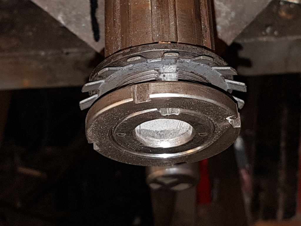
There are two different axle nut sockets: the OEM factory tool is a face-pin spanner with four square protrusions. The late model socket now sold by the vendors is a socket with 4 protrusions inside so the socket completely encloses the nut. This is a much stronger, more slip-proof design, well worth the price. There are also two different axle nuts: one is fully threaded with 4 full height notches; the other has cut-down sides about half way resulting in half-height notches. The Factory face spanner socket will not reach far enough down to fully engage the cut-down nut's notches and may deform or strip the notches at 400 ft-lbs torque.
One last warning: if a previous owner was a little paranoid and used red Loc-tite 271 AND torqued the assembly to 400+ ft-lbs, it may be better to blow the nut off with a cutting torch or use a Dremel grinder rather than hurt yourself- or the assembly- trying to loosen the nut. If the nut simply won't move and you're turning the nut in the correct direction (dextro is right-hand-thread and sinistro is left hand-thread; the marked axles may have swapped sides), try a little heat: hot Loc-tite has an acrid odor instantly detected by your nose. If you smell something 'sharp' while heating, I suggest cutting the nut off. I have several such 'keepsakes'.
Tightening the nut creates an axial tensile stress in the axis to oppose the lateral force exerted by the tires when cornering.
This effort is completely independent of the power transmission (350-400 or 500 or 600 or .... PS), or rather of the corresponding torque, which creates a torsional stress in the axis.
These two stresses are independent, even if they combine to produce the total stress in the axis.
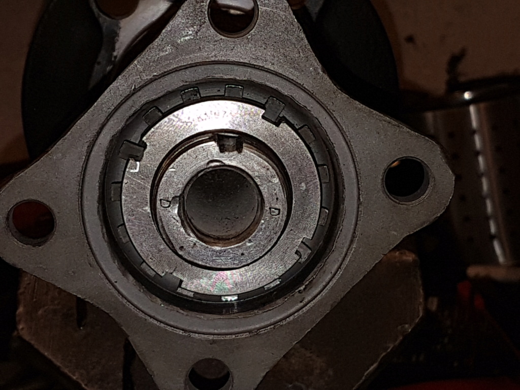
The axial force in turns is only supported by the outer bearing, this is why it is better to replace the outer bearing with a double row ball bearing rather than the inner bearing, but this requires to machine the hub:
The older I get, the more giant tools I buy.... 15 yrs ago I bought a used 0-750 ft-lb Snap-on torque wrench (3/4" drive) specifically for Pantera rear axle nuts. Also works for other very hi-torque car fasteners; original Mini flywheels, RX-7 rotary gland nuts, etc). Because such large torque wrenches are heavy, 3-1/2 ft long and bulky, they are often for sale used at ridiculously low prices on E-Bay. I paid $110 including shipping, in perfect condition. This model (and an even larger 0-1000 ft-lbs one) has a removable handle and a settable dial that lights up a small AA battery powered bulb when a preset torque is reached. So its a one-man wrench in spite of its size. Last time I looked, Snap-On still sells this model new.
Rene
You seem to be the go to guy with the axle nut questions. I have the rear fully dissembled now. Two questions - with your locking nut idea using the SKF MB7 , I suspect you dispensed with the backing washer item 17 ? ( thanks for the sketch jfb!). Or did the locking not go on top ?
I hope so, because old 6997 was missing one on one side. One locking nut was pretty well loose - likely because the washer was missing and the nut was likely just run upon the inner hub lip.
Alternately any ideas where you can buy one of the chamfered washers no 17 ? I have been looking everywhere with no luck.
I purchased two brand new axle nuts, with the locking cut , lh and rh from Halls. Both don't seem to have a run in taper on the thread. Very difficult to thread on the axle because they look like a straight cut thread. The old nuts run on and off no problems.
Any one had this problem ??- very concerned about stripping the thread on the stub axle. Easy job made difficult.

Panteras by Wilkinson for the washer.
The axle nuts are a cinch nut that should bind, in fact this is where many who use new nuts fail to tighten down enough as they think it's tight, but it's not. I always use a high torque air impact wrench, you can actually hear the change in sound as the nut gets to it's final tightness.
I kept the washer 17 to have a good support on the part 16 and to be sure that the nut does not come to lock on the end of the thread on the axis, but compresses all the stacking well.
No, first of all because I didn't know them, but it's still a friction braking system, whereas with the toothed washer it is a positive lock.
Shaft grooving should normally be done on a milling machine, but since I had not done it with a grinder and the result is very acceptable.
Thanks all - Just a note to forestg - after going through the ordering system by the catalog on the Wilkinson I realized the car had been missing both the back and front bearing covers in both the half shaft assembly and a wide variety of plainly non essential obits and pieces.
Could explain the somewhat gritty nature of the bearings when I dissembled them....! Well worth while!
Bear in mind the stock axle washer has a rounded lower surface to match the curved inset on the mating halfshaft hub. Putting the washer in upside down will soak up part of the axle nut torque by bending things without contributing to assembly tightness. The shop manual torque is too low. No need for tricky nuts- the desired torque on that axle spanner-nut is 350-400 ft-lbs. Properly torqued, they survived LeMans & other contests just fine. Do not worry about stripping the threads- the SAE says that a 1-1/2" fine thread like this in mild steel strips at around 1200 ft-lbs! And please- do NOT use red Lock-tite. Poor guys like me have had to remove such nuts with a cutting torch after breaking a factory socket.
Leaving the axle nut washer off effectively lengthens the axle so the splined hub may bottom on the axle splines before things ever contact each other. So the parts will normally be sloppy-loose even at full torque. Both Wilkinson & Larry at PanteraParts.com in NV have new repro nuts & washers in stock, cheap. Good luck.
Thanks bosswench -dont worry I have ordered all of those "non essential" bits from Wilkinsons! May have explained why one nut was virtually finger tight when I took it off.... Also some very nice bluing on the bearing spacer
I have a full blown 500ft lb 1 ' drive torque wrench ( a hand me down from my dear old Dad who was a master mechanic with Ford for many years. ) so the tensioning should not be an issue.
If I had him here I would driving down the road by now! it will be a red letter day when this thing starts up again - 29 years now and counting !
Hold just reread the tread and Bosswrench says no - so sorry - no Locktight for this black duck. It going in dry.
And have new axle washers and have checked - in the right way.
Off to do the business.
Fantastic you have posted JFB . On your picture I notice 17 and 16 are faced together with the chamfer facing to the inside of the assembly. In addition 18 the lock not is shown as having it shoulder outwards. The shoulder on the nut appears to be designed to match the upper part of the inner washer to provide a precise contact area.
- I am just going to get a picture to explain it better.
Here is the orientation these were installed on disassembly . face chamfer on the washer outwards- you are showing it inwards , and bosswench says it should also be inwards. the nut had the ridge on the inside - looking at the drawing the ridge should be outwards

the chamferred outer edge on the NUT is for the pre raised tabs on the locking washer.
since the pantera configuration does not use a lock washer, not really that critical.
HOWEVER, I would go with the norm orientation of the NUT champer against the washer. Possibly the nut's "Flat" outer face will provide a more positive engagement of the socket wrench

Thanks JFB and Bosswrench . Ok - have gone with the axle washer rounded lower surface matching the curved inset on the mating half shaft hub and the raised face of the nut facing to the inside of the assembly mating to the flat back of the axle washer. It seems to make the most sense and it pulled up well. I pulled them down to 350 Ft/lbs.
I don't think they are coming loose anytime soon. Workbench is pretty solid but it started to move a bit - ML63 became a handy bench backstop!
Also attached a picture of the vice mounting jig I made up for the hub. It is heavy high density fiber board around 22mm thick and it had no issue with the loads. And it is pretty kind on the wheel studs.


For the sake of the record at 350 ft /lbs starting from hard snug position, initially pulled up firmly with a 3/4" ratchet drive , then tensioned with a 1" drive tension wrench pulled to 350 ft /lbs tension , the nuts moved from hard snug by a full 1/4 turn of the nut +1/4 " to the final tensioned position .
All surfaces super clean , a little smear of bearing grease. If you could not obtain a tension wrench it would turn out pretty close.
This is consistent with structural friction joint bolting method on high strength bolts. FWIW.
FWIW, the more desirable full-height axle nuts (both left and right hand threads) may be partially split horizontally. This allows the upper and lower parts of the nut to distort slightly in one or more planes during tightening, so as to provide an integral locking function. Whether this distortion returns perfectly upon nut removal is not known. If not, re-use of the nut may mean much higher run-on torque and a lower holding power than what the nut originally delivered for a given torque. In spite of their cost, the safe move is to not reuse such nuts. I don't know what SAE grade any of the available nuts are, either. A pure guess is gr-5.
@Percy posted:F,,,the nuts moved from hard snug by a full 1/4 turn of the nut +1/4 " to the final tensioned position .
This is consistent with structural friction joint bolting method on high strength bolts. FWIW.
Thanks, good to know
did you notice what the thread pitch of the nut.
for the heavy equipment i use to work, Torque was very rarely used (only for the small stuff <1")
"Turn of the nut" was the most used method with actual bolt strain measurement being the preferred. as BossWrench just noted, too many things effect "torque"
Just thinking, for this assembly the amount of bolt "strain" probally is less than the inner /outer bearing spacer compression.
Oh, you said 1/4 turn, what is the 1/4" meaning? (is it, you went 1/4" on the outer diameter past 90 degrees?)
1/4 of the circumference of the nut + about 1/4" at the circumference more. That is it was consistently just a fleas dick over a quarter turn. If you did not have a LH tension wrench this would likely do the job and get you well over 300 Ft/lbs.
I did a google to find a conversion factor between the minimun measurable unit I was familiar with, RCH (red pubic hair) and your use of "flea dick". Unfortunately I did not get an answer and shockingly, I learned the phrase "Hung like a horse" does not do a flea justice!
SO I will assume a flea dick is several times greater than a RCH, but still a small amount ![]()
There is always confusion about such conversions. To really understand them one has to look into the origins of the two measurements. RCH (red pubic hair) originates back to intercourse between the British Screw Association (BA) and British Standard Pipe (BP) that declared several such measurement units . RCH (red pubic hair) was used for all visible measurements and the ubiquitous SMH ( Short mickey hair) for much finer tolerances.
The fleas dick unit , as you would know , was conceived by Dick Whitington, the inventor of the Whitworth system as an attempt to provide a standard that could be easily checked anywhere in the world by the use of the standard flea.
Less well known , the inclination angle of the appendage, was was in fact the basis of the 55 degree thread angle still with us today on our beloved Whitworth fasteners , and copied on by all proper fixings such as Brass Threads, British Standard Conduit (BSCon), Model Engineers (ME), and British Standard Copper (BSCopper).
Both terms , unfortunately , have defied all attempts at direct conversion into metric, although there was a rumor that a conversion table had been prepared by the French Meccano company based on MHS ( Milli Hair Standard.)
It lost something in the translation and never took off.