quote:
How close do you think I can mount the O2 to the head? I have completely different type of headers with all 4 primaries going to the back. The primaries land in a common muffler far down the line.

I am afraid if I put it in the muffler section it will be too far away and not heat up adequately. Since they need to be mounted at least partially upward, this limits my location to the top of the runners here. My concern is that the O2 sensor does not get too hot:


I have O2 sensors as close as 5 inches to the heads and they work fine there. I also have an O2 sensor mounted right before the muffler. It also works fine there. Since most O2 sensors have a heating element built into them I do not think mounting them far down the line would be a problem. However, if they are being used to control engine management (as opposed to just a air/fuel ratio gauge), I was told they need to be as close to the engine as practical...
I would think in the collectors is a good compromise. That's where mine is. Would you want to read just one cylinder?

Most current cars would have two locations. First as close to the engine as will fit which means right after the headers but before the pre-cat and the second after the cat.

The closer to the engine that you go, the shorter the lifespan of the sensor.

Of course those locations are for different reasons than yours.
Last edited by panteradoug
So guys, if you run IDF's and air cleaners, are you going to have a fire? I'm sure it has to do partly with the cam selection. I read an old post from Dave (Whiplash) that said he took his air cleaners off after having two air cleaner fires. Not having air cleaners seems like it would shorten the engine life.

Are you going to have engine popping when decelerating with webers, or can that be tuned out?

Do elevation changes make huge drivability issues?


I have been thinking about this topic for a week or so, and here's another thought with that Cain manifold: Run TWM/Borla IDF throttle bodies and EZ EFI... In other words, run IR fuel injection under the decklid in a different way than the common Hall Manifold/IPSCO throttle bodies or Kirby manifold/IPSCO throttle bodies.
http://www.youtube.com/watch?v=JRdwWgSGqvc

Watch the top of the carbs in this video. Do you see the fuel mist coming out of the stacks?

That is the reversion caused by the overlap on the camshaft.

This video has a better side view of the reversion.

http://www.youtube.com/watch?v=caGWuuXqZq4


It doesn't matter what carbs you use, it is the effect of an individual runner intake manifold that has no common plenum.

The Trans-Am Boss 302 with the dual Dominators does it, so does a Doug Nash with dual Autolite inlines.

If you put any kind of an air cleaner fabric over the stacks the fabric will be saturated not just by fuel, by atomized fuel.

The ONLY way with carbs not to have issue is run no fabric over them at all AND/OR use a camshaft that has something like 28-30 total degrees of overlap. That reduces the reversion to almost non-existant.

If you look at cam specs, that is very close to the stock 351-c Cobra-jet cam these engines came with new from Ford.


There are two 351c cam profiles I know of that are refered to as "Weber Cams". The one sold by "Inglese" is the Comp Cams version. Hydralic lifters, .586 lift, yada-yada-yada. The other is by Cam Techniques and is the virtually the same.

Look at the power numbers and the flow rates of the heads on these engines. You will notice that the engines start to make 500hp + with over 600 lift. Heads start flowing over 300cfm over 600.

The "Weber Cams" only start to approach this lift. The CJ cam isn't even 500 lift. It is 480 something.


Whiplash I think, is talking about the comp car he has? The factory comp cars ran 48IDAs. Holman-Moody solid roller lifter camshafts and were the same as the 4v Bud Moore race engines with his special "race plenum" intake manifold. (Ram boxes for lack of a better, or correct term).

The GT40 Mark I's ran 48IDAs Webers and the T/A Boss 302s, ran the dual Dominators on an IR intake "XE" manifold, have air chambers over them on which the mist accumulates like early morning due on the grass. All run with regular big overlap race cams. The 289 "LeMans cam" has 82 degrees of overlap. No special Weber cut cam there.

You need to keep the mist away from the headers and run no stack covers and you are generally ok with fire risk. I can tell you that you smell the gas when you come back off of the track OR back to idling with no motion after a flat out run.


The engine itself is going to have a shorter life span because of the cylinder washing from the volume of fuel being "dumped" into the engine. It doesn't matter if it is IDAs or IDFs. The end result will be the same.

Regardless of how clean you can get the carbs to idle and run, every time you mash the throttle, or even just move it, you have eight accelerator pumps jets doing their thing and the instantaneous black smoke from the exhaust is noticeable.

Interestingly enough, not many talk about the pump jets while tuning these carbs. I found that I could almost eliminate the pump shot (.050 vs stock .100) with no noticeable effect EXCEPT it made the cold engine very difficult to start without them.

The oil rings do not like it and you will build up a black film in the exhaust which is the engine oil you are washing out of the engine. It's the accelerator pumps doing the cylinder washing.

THEORETICALLY, you could reduce 7 of the pump jets to minimal except for 1 and use that one to start the cold engine...THEORETICALLY. I don't know how practical that actually is though. The engine is VERY easy to flood trying to start it cold if it doesn't fire up on the first crack of the key.

In addition, the air filters just make the engine harder to tune right and if you are going to do open track days then you take the filters off.

However, I do that even with the dual Holleys which seemingly adds 100hp to the engine at WOT.


The only way to avoid most of these issues is to run IR EFI, as you mentioned. Then that's an entirely different animal, but they still will like to run around naked with no tops. Why not? I like to encourage that behavior as much as possible too?

The IDFs don't fix any of these issues. Most of the issues are created by using carburetors on an IR (independent runner) manifold. The IDFs just have a different idle system. Are you SURE they fit UNDER THE SCREEN? The front of the screen is very low.


Consider this...even if they fit.

Rule of thumb on any carb is you need a MINIMUM clearance over the top of the intake stack that is approximately equal to the OD of that stack, i.e., 48mm, 1.89". This includes air cleaners. Many of the air cleaners offered, simply stated are built WRONG for these carbs. Maybe they belong on your leaf blower but not on a Weber with velocity stacks.

The IDAs were run by some of the biggest race teams ever assembled, and some of the most successful too. There is a reason they were used, and there is method to the way they were applied. Think you are smarter then Fords GT40 program with unlimited budget? Really?

Want to duke it out with Phil Remington? Go ahead. Be my guest. I know better.


IDA's always pop at deceleration, not bad, but a sure characteristic that you are running IDAs. I would PRESUME the IDF's do also?


Running "Webers" is hardass. There is no way to pussyfoot around them. A love/hate relationship with Malaria type re-occurrances and Lord knows, psychotic masochistic undertones? But then again, you would probably only know this all from experience, are hopelessly addicted and understand that having the ultimate doesn't stop the desire for more. Frankly, it just never ends.

Oh..."your mileage may vary". Big Grin
Last edited by panteradoug
quote:
Originally posted by PanteraDoug:
What are you doing for a roll bar? Is it in the engine compartment?


I wanted to bring it into the engine compartment but I could not figure out how to make it removable. I wanted it removable if for no other reason the paint process.

I did mount it in the cab but it comes through the back ties into the roof at the decklid hinge then comes back into the wells. The wells are reinforced with a plate then a built a ladder bar:

http://www.rc-tech.net/pantera1/rollbar/roll.htm


http://www.rc-tech.net/pantera1/ladder/lad.htm
1)Thank you for the compliment but I post it to try to illustrate what someone is getting into with these 8 stack IDA setups.

2)I had Halls 3 point roll bar in the cabin and got tired of just catching my left hip on it getting into and out of the car. Sold it to LastPushbutton, Bill Gaino. He loves it.

It didn't really occur to me that the profile on either side of the firewall bulkhead was the same in the cabin or in the engine compartment until too late.

I invision being able to cut that bar into left and right halves, welding flanges to it and bolting it to the roof as well. This would let me have my cake and eat it too since I could run the rearward braces as well.

Why can't that all bolt together?

Gary Hall had cautioned me that the gas tank would need to be "slightly modified" to clear the bar. He had built a bar for "Purple Passion" to stiffen the chassis when he turned it into a T top. It shows in one of the Hall Pantera color catalogs but apparently it is the only bar ever built and the fabricator, Bob at Precision Proformance, refuses to build one. Sounds like a tough job?

When I asked Bob at Precision Proformance about it, he said the tank would need a lot of modification to do that.

Why not tie that together with doing a new stainless tank is what I thought?

Anyway, thanks for the links on your bar fabrication. Looks like you have a lot of fun with that? I want minimal fabrication chores to do these days. I've had too many years of having cars apart on a "two week" project? Wink

Vacuum. Interestingly enough, my manifold came with a 3/8 pipe port drilled and threaded into the #8 intake runner.

This is for the vacuum line for the brakes. It makes enough vacuum to operate them.

I've been thinking lately of plumbing the runners together for a vacuum gauge. I think I want to put carb spacers in and plumb the fittings to them? Maybe 1/16npt to keep it minimal OR maybe press in 1/8" steel tubing like a carb would have in it's base for vacuum connections?

Whether or not those -3 lines provide enough vacuum is going to be trial and error. If not, like you said, you can always try a vacuum reservoir hidden somewhere on the firewall?
Last edited by panteradoug
Thanks for the info on the vacuum; that's helpful. You know on my MGB (GM V6) I put the 02 and vacuum gauge behind the radio delete plate which is held in by super magnets. Tuning the car with 02 has been fantastic:


As far as the roll bar behind the firewall I think if you broke it up you could make it removable but I took the main hoop and spent the afternoon trying to snake it in. I was never able to get it in. If you do let me know I would like to see how you do it.

As far as the gas tank, did you see my headers?

Stock tank wouldn't come close. This is the tank design I am working with. I am just waiting my turn at the laser to cut the aluminum. We were down for a week and a half due to a lightning strike and personal projects are on the back burner right now.


I wish I could fix it that easy. This exhaust is radically different.


I am also moving the tank to the right side of the car and putting an oil cooler on the left. I don't like oil lines running under the car. I am ducting the air through the side vent with a fan.

You can see how the primaries shoot out and the aluminum on the left inside which will duct the air through for the oil cooler:


quote:
Originally posted by Corey Price:

So guys, if you run IDF's and air cleaners, are you going to have a fire? I'm sure it has to do partly with the cam selection. I read an old post from Dave (Whiplash) that said he took his air cleaners off after having two air cleaner fires. Not having air cleaners seems like it would shorten the engine life.


Corey

I know you're capable of researching the internet ... and that's what I encourage you to do.

If a person's only exposure to the world of Weber carburetors is the IDA, then it has only scratched the surface, and not the best surface either. Weber carburetion is popular world wide on smaller engines, both with plenums and with individual runners. The american V8 muscle car crowd are the only hobbyists that adore the IDA carburetors, its actuallly a small market for Weber. As they were originally designed they are a racing carburetor for a motor that is either accelerating at WFO or braking. I'm sure there are guys who can modify them to work better ... if that's where your head is at.

The IDF's are used in many more applications than the IDAs; like the DCOE, the IDF is a very popular twin throat racing & high performance carburetor. It has been used as oem equipment in a few limited production vehicles, including a Ford Escort (the European Ford Escort RS2000 Group 1 cars). And it is accepted by very many sports car hobbyists as an acceptible replacement for various Delorto and Solex carburetors. It is also sold by Pegasus Racing due to the demand for the carburetor. IDF Webers are offered in 40, 44 and 48 mm bore sizes. The main, idle, air correction and accelerator pump jets, the emulsion tubes and venturis, are interchangeable. It has a float design that makes it very popular for off-road applications, a vacuum advance port, and four progression holes for smooth light-accelerator response. The differences between the IDA and the IDF, like the additional transfer circuit, add up to make a big difference in performance. You can bet the IDF would not have been selected for oem applications if it's calibration were as easily upset as the calibration of the IDA is reported to be.

Individual runner carburetion has been used on many production automobiles and motorcycles ... AND Every Single Cylinder Internal Combustion Engine Ever Made ... think lawn mowers, leaf blowers, chain saws, generators, etc. They don't have problems with altitude and fires. So continue your search on the internet, you'll find the answers you seek. I'll tell you what I know. Inglese uses wide lobe separation (115 degrees) for the cams he sells for IR. So one can assume from that bit of info that overlap is the source for some of the problems with IR systems. I have helped a couple of guys install IR weber systems in my past; one was an IDF system on a Ford Fairlane (Windsor) V8 ... the owner was happy with the results. Another guy chose an IDA system for his SBC, he was unhappy with the results, so he eventually sold off the IDA system, purchased an IDF system, and has been using it for over 20 years.

Pictured below is an IDF system fitting under the engine screen of a Pantera

-G

Attachments

Images (1)
  • weber_IDF
Last edited by George P
quote:
Originally posted by Kid:
If you want/need vacuum only for the brakes, you could consider to run an electric vacuum pump in the front, instead of the hassle of working with a line from the back to front. Some modern cars (electric and non electric), do run those little electric vacuum pumps.


I considered an electric long time ago but I already have added many electric items; electric power steering pump, trans cooler pump, fans, etc. I like the simplicity of a vacuum line if it works ok. I can always change it if it doesn't.
Doug,

So I think you're trying to say that the cams that work best with Webers are lower lift and less duration (and overlap). Your post is misleading- do the "Weber cams" have .586" lift, or do they have .5" lift? Are you saying that a street-able Weber-compatible cam would make it difficult to make 500 hp without tons of reversion? Is this the cam you're talking about- http://www.compperformancegrou...e=FordWeberCamshafts


George,

I have been searching, but probably not in the right places. I'll look some more.


If you could build a IR EFI system that would fit under the decklid with off-the-shelf parts & no significant fabrication, modification of existing manifolds for injector bungs, etc, wouldn't that be cool? I think we have that here in addition to the Weber IDF idea. Yes, there will be some fab work on a center bell crank and linkage, but I'm sure that it isn't anything new or super difficult. The Cain manifold has a tower for the bell crank in the center.
That is the "Inglese" "351c Weber Cam" (CompCams). The CamTechniques is as I recall, .586 lift. That cam I saw run on the track with this setup. In my opinion, the car was way down on power. It didn't even sound right and have that howl you hear from a distance?

But...first off Corey, you have to define the term "BETTER"? Everyone will have a different interpretation of the term. That's where it gets a little sticky (controversial).

The IDAs offer the possibility of this duality, in that they can be "tuned", as in tuned down to make them more livable as a mostly street driven induction system, OR they can be tuned to run them flat out as was done in the 60s and 70s as the ultimate (for the era) naturally aspirated induction system.

The carbs themselves are easily changeable, relatively speaking, from day to day because of the top access to the jetting.

The camshaft of the engine is not.

It is up to the owner to decide the nature of the engine.


To me, it is difficult to live with them on a daily basis with a big overlap cam like those run on the race cars. Being a Walter Mitty type I suppose, that's what I really want though. Dam the practicality?

By the same token, the nature of this setup of constantly wanting more out of them makes running the "Weber Cams" somewhat of a bear trap.

Those cams are simply de-tuned to eliminate the reversion of the fuel.


As with any cam selection, you really have to try both of what you are considering. You can only get a cam recommendation from a cam company. It's up to you to decide which and it is a lot of work to try various cam profiles...but that's the gig?


For the amount of usage I give the car, running the carbs with the open stacks and the big overlap is ok with me. I'm not crazy about all that fuel being blown back, but knowing the alternatives I can accept that fait.

When you select a camshaft, you match it to the flow characteristics of the heads do you not?

If you are making your maximum power at say .650 lift, why would you put in a cam that is .571 or .586?


The simple thing in the end I think is not to get invested into Weber carbs in the first place. The better alternative now is to use the Classic Fuel injection which looks just like them. Then all of this debate on which door to choose, the Lady or the Tiger becomes purely academia.

Problem solved...no more reversion. No fuel in the bowls to be reverse flowed because now there are no fuel bowls?

Everything computer designed, matched, and optimized from the beginning. Then you just tune the setup with your laptop. "Hands on" ultimately is sooo over rated...right?
Last edited by panteradoug
Tom that is an up-loaded picture, not a linked picture. You have to be logged-in to see the picture, if a person is not logged-in they see the red circle.

Corey the IDF is popular with VW (dune buggy) and classic Porsche owners. I believe its the carb of choice for the poeple who race the 1.6 liter in line Fords too. Check out various other small sports car groups like Fiat, Alfa, Lancia. A forum for rally racing will probably have info too.

I hope everyone understands I'm not trying to step on any toes, I respect you guys who love your IDA Webers. But Corey's original post asked for IDF information, and there is not a lot of experience with them among our members. So I made the suggestion for him to look elsewhere, because I know that carburetor is actually very popular in other areas of motorsport.

-G
I have posted this in a similar thread some time ago.
But here it is again.
A different take on the Weber look, using injection.
My Pantera runs fuel injection, 8 x 48mm throttle bodies.
Similar set up to Weber’s & a similar look.
This is an old “Pantera Performance center” kit I found on Ebay.
I assume from the 1980’s.

Velocity stacks I custom made, they are in two pieces where the top screws on to clamp in place a stainless mesh screen.
I have run the car with & without the screens on the Dyno & it made zero difference to the tune or power output.
Not that was easily noticeable anyway.
Computer is a Motec with crank angle sensor, TPS & MAP sensors only.
I rebuilt the throttle bodies & re-set the butterfly clearances.
Runs really nice, easy to start & reliable.
Combined with the 11:1 CHI 4V heads it made more responsive & snappier power.

I don’t run the car in the rain, nor do I wash the car with water.

The only issues I have had is balancing the throttle bodies to make sure they are all breathing the same amount at idle.
Also, because of the high air flow of 8 x 48mm butterflies it requires a corresponding amount of fuel when snapping the throttle open from idle.
So running rich at idle was causing the spark plugs to foul.
Re-tuning the car at idle & leaning off the fuel didn’t work, it simply backfired.
So now I have changed the Spark plugs from NGK BCP6ES to a hotter BCP5ES.
Yet to try it & see if it has cured the plug fouling problem.

The other issue is that each throttle body has its own return spring. And they certainly are required to get the butterflies to snap closed.
But combine the tension of 4 x springs & it makes a very stiff throttle pedal.
So at some stage I’m going to have to look at a progressive throttle linkage to gain some more leverage & better throttle control.

In regards to Vacuum.
I run an 8” dual diaphragm booster as my master cylinder is 1 1/8” bore, (4 piston rear calipers).
I also run a vacuum bottle up front with an extra check valve.
I tried supplying vacuum from one port & it was no where near enough.
So tried 2 ports, still not enough.
Then went to four ports & that was sufficient.

regards,
Tony.

Attachments

Images (1)
  • Engine_copy
That's a very early system. Generally you need three inputs to make the program work. Oxygen sensor, TPS, MAP.

There is the identical set up here on a wide fender car Dennis did and the car runs like do-do because it lacks an oxygen sensor. Glad yours works ok.

Last I heard about the car here is it was being "revised" to include more inputs.
quote:
Originally posted by PanteraDoug: That's a very early system. Generally you need three inputs to make the program work. Oxygen sensor, TPS, MAP.

That would be a pretty crude set of inputs by today’s standards. However, some have achieved good results running IR EFI set ups with scheme’s as simple as just Alfa-N +RPM if the owners put the time into tuning under both controlled and road circumstances. If you have stable altitude and atmospheric conditions it can be sufficient but sort of depends on your engine specs, driving, and expectations. A big cam and a lot putting around town driving will require more effort to produce more civil street manners, but IR with good ECU and additional sensor schemes can be uniquely suited to do so. In closed loop most find that that O2 sensors aren’t very useful for much more than trimming idle and cruise, even with wideband O2 sensors. They are of course essential when it comes to emissions control if that is important to you. Things change too rapidly for closed loop O2 control to be very useful across the entire rpm range as far as performance goes for most street tuners. The race team’s set ups are much more sophisticated and can be a totally different story in this regard. I think wide band O2 is certainly useful input for tuning but position in the exhaust circuit and leaks can often create transient responses and false readings. For street driven IR, I’d recommend TPS, MAP, RPM, Inlet air Temp, Engine/Coolant temp, wide band O2, and maybe Idle Air Control (IAC), depending upon your control scheme. I’d also recommend that you run a crank trigger and gain full control of your ignition maps while you’re at it; why not have any advance curve for any set of conditions? Many of the modern ECUs have excellent subroutines that give you a great head start on schemes for idle, cold start/warm up, off-idle and enrichment schemes, etc. A lot of sensors and full control or fuel and ignitions MAPS means great potential for tuning but will also mean a lot of tuning to achieve the results. Be prepared to invest the time. Most find they can get to acceptable results fairly quickly and then just evolve and refine their schemes over time.
quote:
There is the identical set up here on a wide fender car Dennis did and the car runs like do-do because it lacks an oxygen sensor. Glad yours works ok. Last I heard about the car here is it was being "revised" to include more inputs.

I’d say it’s either poorly sensored/equipped and/or tuned but the O2 sensor is probably the least of the issue if that is the case.

Best,
K
quote:
Originally posted by Edge: My Pantera runs fuel injection, 8 x 48mm throttle bodies.
Similar set up to Weber’s & a similar look. This is an old “Pantera Performance center” kit I found on Ebay.

I followed your build Tony and must compliment you on executing it very well. It’s very nicely done.
quote:
I assume from the 1980’s.

Probably at least mid 90s or more recent. If it has TWM throttle bodies without the “Oldham” couplings, I believe Garry Polled implemented those about 10 years ago. He installed those between the barrels on his IDA throttle bodies because he said in instances where there was big temperature rise, the thermally enduced growth would cause binding due to the difference in linear thermal expansion between the steel shaft and aluminum TB. I have never had that issue (at least between barrels), and think this is more likely attributable to deformation of the intake manifold while mounting with the throttle bodies already mounted. This binding was a common problem on the older Hilborn, Enderle, Falconner, etc. and like units with a single shaft spanning all four barrels. Now, the connection between the two TB shafts on each bank on a set up such as yours is a totally different story.
quote:
Velocity stacks I custom made, they are in two pieces where the top screws on to clamp in place a stainless mesh screen.

Those are very nicely done.
quote:
Computer is a Motec with crank angle sensor, TPS & MAP sensors only. I rebuilt the throttle bodies & re-set the butterfly clearances. Runs really nice, easy to start & reliable. Combined with the 11:1 CHI 4V heads it made more responsive & snappier power.

That’s pretty Spartan as far as sensors go. I would think you would want to add several temp sensors for inlet air and coolant/engine temp. When you say MAP, are you trying to run a speed density scheme such as employed on a 4-Barrel by using a plenum plumbed to each barrel of your IR set up? Or just using it as atmospheric pressure correction? When you mention crank angle sensor, are you able to actively manage your ignition maps as well? As I mentioned in the earlier thread, the rest of the sensors such as O2, idle air valve, are really just for idle, warm up enrichment schemes, and leaning at cruise.
quote:
The only issues I have had is balancing the throttle bodies to make sure they are all breathing the same amount at idle. Also, because of the high air flow of 8 x 48mm butterflies it requires a corresponding amount of fuel when snapping the throttle open from idle. So running rich at idle was causing the spark plugs to foul. Re-tuning the car at idle & leaning off the fuel didn’t work, it simply backfired. So now I have changed the Spark plugs from NGK BCP6ES to a hotter BCP5ES. Yet to try it & see if it has cured the plug fouling problem.

This is where you might benefit from some additional sensor input. Many of the aftermarket ECUs now have many algorithms and subroutines for cold start, off idle enrichment, warm up, idle control, that are very useful and user friendly. Not sure what Motec ECU you’re running. I’m not very familiar with them but in the past have known them for their high end racing stuff. Many people have had very good results plumbing a vacuum line from each runner to a plenum and using an IAC and closed loop O2 to regulate idle. Those doing so on plenums that also run their MAP sensor may find some problems caused by the IAC altering the MAP signal. Some isolate the two plenums. IT should be noted that these plenums can be sized and remotely mounted.
quote:
The other issue is that each throttle body has its own return spring. And they certainly are required to get the butterflies to snap closed. But combine the tension of 4 x springs & it makes a very stiff throttle pedal.

I’d recommend you either put lighter springs in each TB or as you mention, consider different linkage. A spring on each TB is a good safety measure.
quote:
So at some stage I’m going to have to look at a progressive throttle linkage to gain some more leverage & better throttle control.

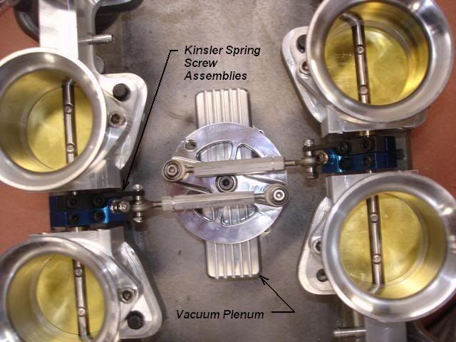
I’ve fiddled with a bunch of schemes and for the last ten years have always used the one pictured on the IR system below. I use this scheme on all my IR set ups from EFI, to Weber IDAs, and Inline Autolites. The throttle plates in each bank counter rotate to promote flow symmetry. The spring loaded balance bar linkage in the center between the TBs are very important. The ones pictured are a Kinsler product but the allows for axial growth and misalignment between TBs without binding. The cable actuated wheel is important feature of the linkage. In the initial position, the link arms are set close to center so that it takes much more rotation of the wheel in the early movement to produce the same change in angular position of the throttle plates. This gives good resolution with the accelerator pedal. It then get’s gained up progressively as you put your foot into it. The cable actuated wheel also has one subtle advantage over typical bell cranks schemes; you can calculate the diameter of the wheel for the exact amount of pedal/cable stroke for a given degree of rotation. The other thing is the mechanical advantage of the wheel on your linkage is always the same because the cable pulling force is always applied at a point the makes the applied lever arm half the wheel diameter. I mount the wheels in ball bearings and the linkage feels very nice. High quality linkage is very important for IR for performance, safety, and reliability to stay in tune.


These set ups will fit under a Pantera deck lid with 2" tall filter elements without notching the lid.
quote:
In regards to Vacuum. I run an 8” dual diaphragm booster as my master cylinder is 1 1/8” bore, (4 piston rear calipers). I also run a vacuum bottle up front with an extra check valve. I tried supplying vacuum from one port & it was no where near enough. So tried 2 ports, still not enough. Then went to four ports & that was sufficient.

Mixing your comfort accessories with performance is like mixing business with pleasure. I’d recommend running a vacuum pump and separate plenum and circuit for your brake booster and call it a day.

Take care,
Kelly
The system does include coolant temp & RPM.
When we made the new exhaust system we fitted a socket for the O2 sensor.
This was plugged in during the dyno runs to get the correct fuel/air ratio, but the Motec does not use it.
The MAP feeds off of a vacuum port on each throttle body.
I’m pretty sure it’s for atmospheric pressure correction.
The Motec has provision for more sensors & given more time in the future it will be expanded upon to refine the tune.
Inlet air temp sensor is possible, could be fitted above the velocity stacks, or in the side of one.
I also have a cam angle sensor which plugs in where the Distributor was, not set up yet.
There is a spring loaded connection between each throttle body that has a screw adjustment for synchronizing.
I’m not right up on the tuning of this system & I need to learn a lot more.
It’s been a steep learning curve.
I have simply done all of the mechanical side & the manufacture of components etc.
I have a friend who does the electrical & another who has tuned on the Dyno.
So I rely heavily on them for tuning input.
Kelly, your comments here are most helpful, the more information the better.
I like the Kinsler throttle wheel that would give a nice progressive feel.
I did consider a vacuum pump but was trying to get it right using manifold vacuum & reduce the number of electrical accessories.
I may need to chase down an OEM type vacuum pump from a modern car.
We are machining up new rims right now, (17x9.5” front & 19x13” rear).
I have some 8 piston Brembos to put on the front; they tuck nicely in the 17” rims with big Wilwood rotors, so I will need good vacuum supply.

Regards,
Tony.

Attachments

Images (1)
  • Cooling_system_copy
We'll let Corey's thread get back on topic one of two ways.

If one of the members wishing to discuss IR EFI wish to start a new thread on that subject I'll gladly move the appropriate posts to that thread, and the off topic conversation can carry-on over in the new thread.

Or we can just let the off topic coversation end, and allow Corey's thread to stay on topic.


-G
I take back the part about the thread getting off-course. The IR EFI stuff is great to augment the Weber IDF stuff.

I've been researching IDF's a little more. I am going to order a few books on tuning. I have also researched IR EFI a little more, as well as the standard 4-bbl carburetor. There are so many choices that it's actually fun to think about!

I sent a message to the company that has the manifolds in Australia. I know there are other people who were looking at this manifold and hoping for a group rate or going in on shipping, but I haven't heard any more about it. I am considering using this and IDF Webers or using 2930 Series TWM throttle bodies for IR EFI. Looks like the manifold has a center post that is probably meant for a bell crank or for the wheel approach...

If I do this, I might spring for some AFD heads as well and see about getting it all shipped together.
I have been looking into IDF's a bit more again for fun.

It turns out there is a local VW shop near where I live (in Salt Lake City) that rebuilds Weber carbs. I talked at length with the guy who rebuilds and tunes Webers, Solex, Zeniths, Delortos, etc. I even compared first-hand IDA and IDF carbs and investigated differences with them both in my hands. If anyone is wondering, the IDF is about 4" tall from bottom to top of carb, not including the main jet extension. IDF's are made to take air filters, have the same jets as IDA's, and have four progression holes instead of the IDA's standard two. While the IDA can have another progression hole drilled, (the so-called "intermediate circuit") the IDF is the true street carb according to the rebuilder/tuner. The rebuilder/tuner seemed to like the Delorto carb that has the same mounting pattern as the IDF, but said that they are no longer being made and scrounging up four 48mm versions all the same would be much more expensive than four brand-new IDF's.

Four 48 IDF's are actually cheaper than four 48 IDA's...
It isn't just the height of the carb, you need 48mm clearance over the top of the velocity stack clearance to the deck for proper flow.

The IDA is about 7" to the top of the velocity stack but I think the main advantage of the IDF is that the manifold is lower then the IDA's.

You can run the IDA's with a shortened velocity stack and auxiliary venturi like the Cobra Daytona Coupes did. You can get them down to about 6".

I've done this and it doesn't seem to effect the performance of the carb at all.

I would also say that you can come as close as about 1-1/2" clearance to the decklid.

You could shorten the IDA, cut our the reinforcing to the decklid and probably clear without cutting through the skin.
Doug, you might have missed the point of the IDF discussion. Hope this helps:

quote:
Originally posted by PanteraDoug:
It isn't just the height of the carb, you need 48mm clearance over the top of the velocity stack clearance to the deck for proper flow.


IDA's need velocity stacks to help the venturi work properly as the guy at the shop I visited said. IDF carbs do not have the same venturi design and should not need velocity stacks. IDF carbs were made to readily accept air cleaners due to the flat top plate. To get an IDA to accept an air filter, you have to use a velocity stack extension and modify it. Please google a Weber IDF and compare the image with your IDA's. They are different carburetors. If you needed the velocity stack, a standard 4-barrel carb would need it too, right? Yes, the velocity stacks create a nice transition for the air to go into the carb to reduce loss of flow, but I would be surprised to see it make a big difference for the street-going average joe with an air cleaner instead of the velocity stack. Give me an air cleaner & better engine longevity any day in trade for a small percentage of power lost.

quote:

The IDA is about 7" to the top of the velocity stack but I think the main advantage of the IDF is that the manifold is lower then the IDA's.


I held both an IDF and an IDA in my hand yesterday. The IDA is around 1" taller than the IDF. The IDF has a flat top plate, whereas the IDA doesn't. The IDF is 4" tall and the manifold is shorter. The advantage to the IDF is actually the short size, ability to run an air filter without stack adapter, more progression holes for better transition from idle to full throttle, and you can run it under the decklid and engine screen without cutting through the decklid and engine screen.

quote:

You can run the IDA's with a shortened velocity stack and auxiliary venturi like the Cobra Daytona Coupes did. You can get them down to about 6".


IDF's will be shorter, even with velocity stacks.
Hum. I don't think I missed the point. They are two different carbs.

Not intending to be argumentative, lecturing etc but the point of multiple carbs on an individual runner manifold is for performance.

Everything about the IDF is a compromise system. Why would I want to compromise with less performance?

Sure they look great. In design there is a school of thought that form follows function. If they work...they are beautiful.

So maybe you're right? I don't get the IDF's? Smiler
Last edited by panteradoug
If you plan to go for a kind of linkage which will connect the carbs of the two sides by means of a rod, then study the movement of your butterflies closely. I can't properly judge the levers used in the 302 set-up your blog links to, but I found out my original set-up made the butterflies of both sides move in an ansynchronous way. They would close at the same time, and reach WOT at the same time, but midway there was a significant difference. The set-up as I originally had it, is in use though by many people using Webers. Apperently nobody notice(d) this...

Add Reply

Post
×
×
×
×
Link copied to your clipboard.
×