Some time ago, I decided I would put a roll cage in my car. Mostly for occupant safety, but also thinking about possible track day adventures. The SCCA rules describe the requirements, and I also looked at the work of other Pantera owners. (Thank you all for documenting your work; you know who you are).
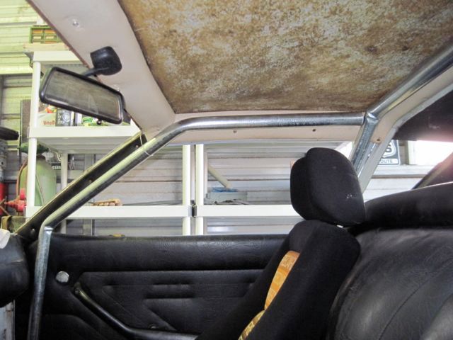
I started by locating the end points of the main hoop and side hoops. You can see I’ve temporarily installed some of the interior trim. The green marker in these photos is a milk jug cap, which just happens to be 1.5 inches in diameter, the size of the cage tubing:
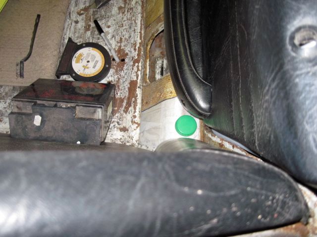
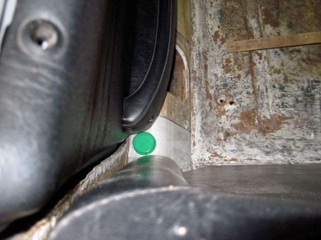
I did not have an idea how to make the tubing pieces fit, and I imagined that trial and error would take a lot of time and effort, along with a lot of mock up material. After giving it some thought, I decided to try a 3-D CAD model. Essentially, I would make a 3-D model of the car’s interior, and then draw a roll cage to fit within it.
These next pics show the set up of the X-Y-Z coordinate reference. Nothing more than some wooden yard sticks clamped in place inside the cockpit, and another yard stick with a level taped to it, free to move about and measure things.
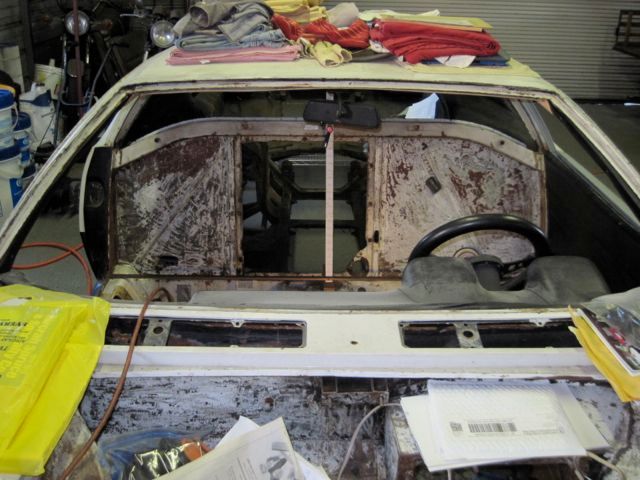
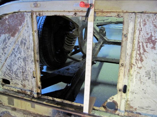
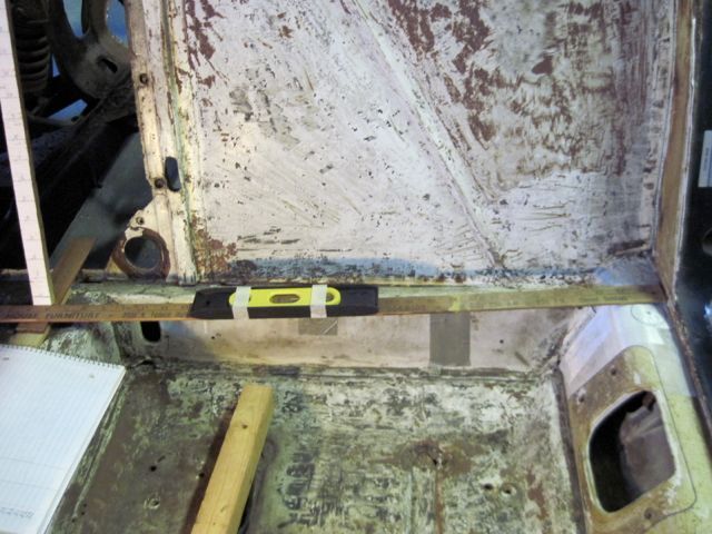
Except for the mounting points, I did not measure where I wanted the roll cage to be; I measured the constraints. In other words, I measured the things the roll cage would have to clear. One point at a time, I filled in a table of X-Y-Z data points, with notes about what it was I had measured. I suppose this took a few days of shop time, a “shop day” being usually only a few hours a day. When I entered this data into my CAD program, the result was a crude, but accurate, model.
Once in the CAD program, I could model the roll cage, and try different designs. I let the computer figure out the lengths of the tubes and angles of the bends. I bought some 1.5 inch electrical conduit to use for a mock up. The bends kinked kind of bad in the mock up, so I’ll have to take care to avoid that in the real thing. The mock up verified for me that I had a good model, as these photos show:
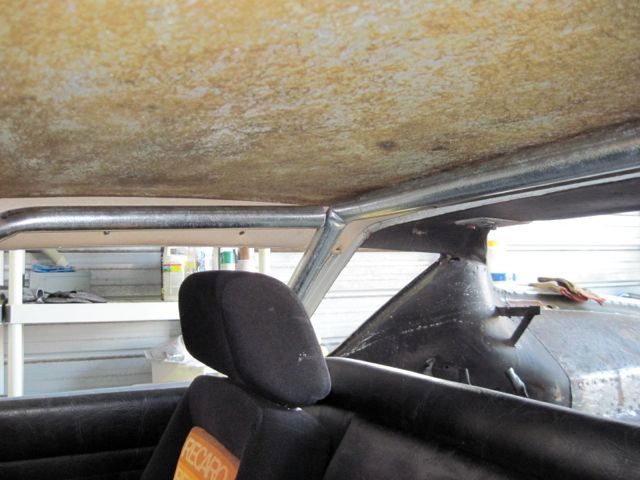
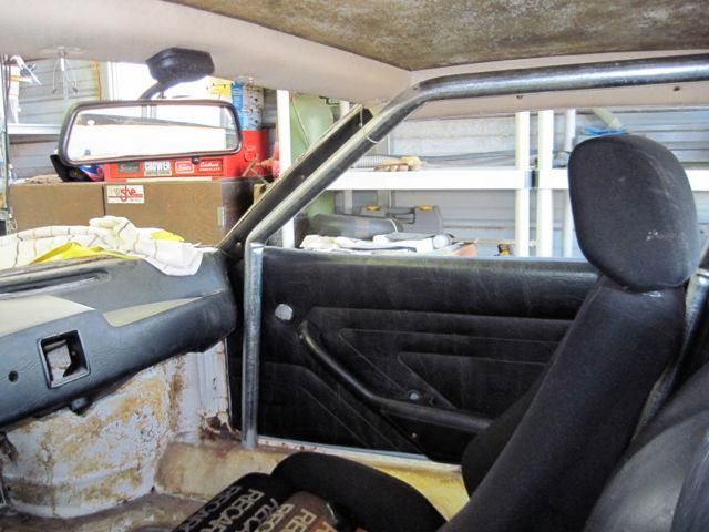
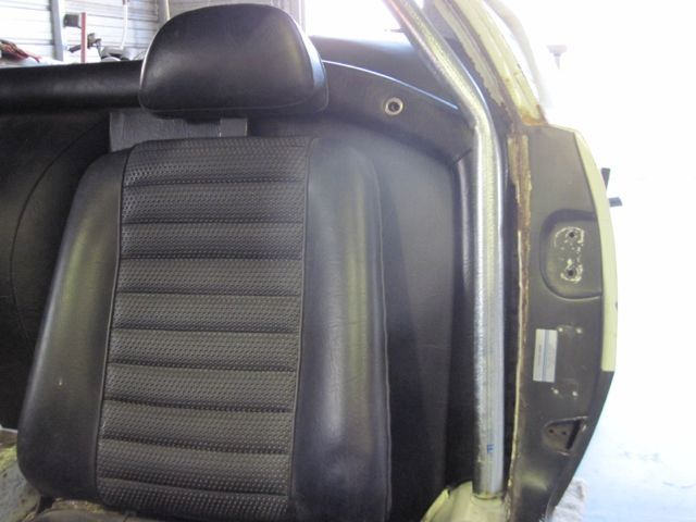
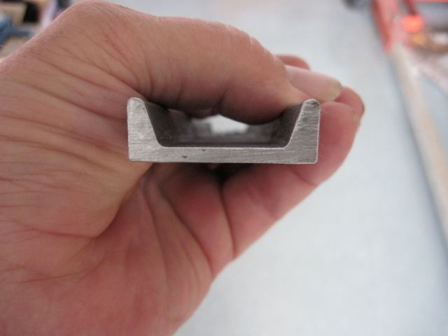
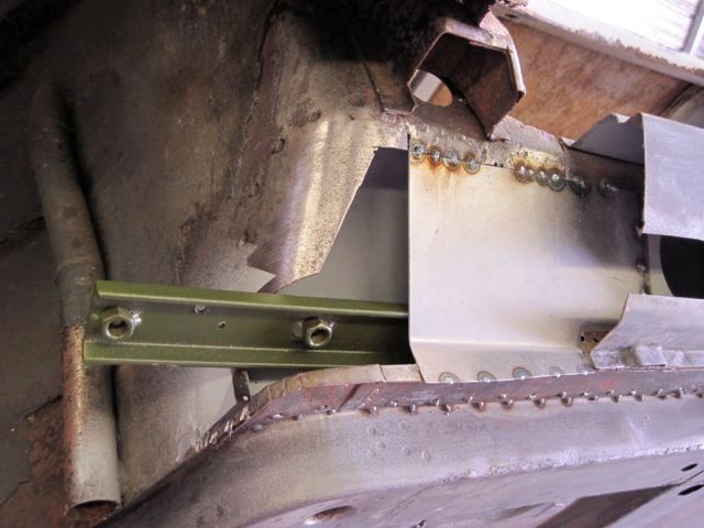
While doing this I was thinking about the mounting points. Attaching a tubular structure to a unibody is not easy. Most designs use a steel plate contoured to fit on the inner rocker and held with multiple small bolts. I decided to use a different approach; a structural stiffener made of channel steel, inside the rocker. The roll cage will be welded to short segments of the same material, and these will bolt to the stiffener. The inner rocker metal will be sandwiched in between. These pics show it better than I can explain it.
The channel steel stiffener cross section:
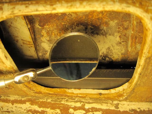
The edge of the seat belt retractor opening is rolled in. I had to trim maybe 2 mm off the inside edge to allow the stiffener to sit flat on the underside of the inner rocker sill.
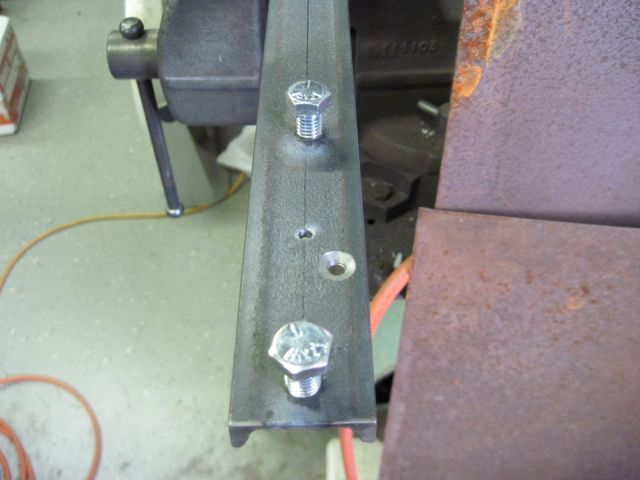
The mounts are two 3/8 - 16 grade 5 bolts at each mount, with nuts welded on the back side for more threads:
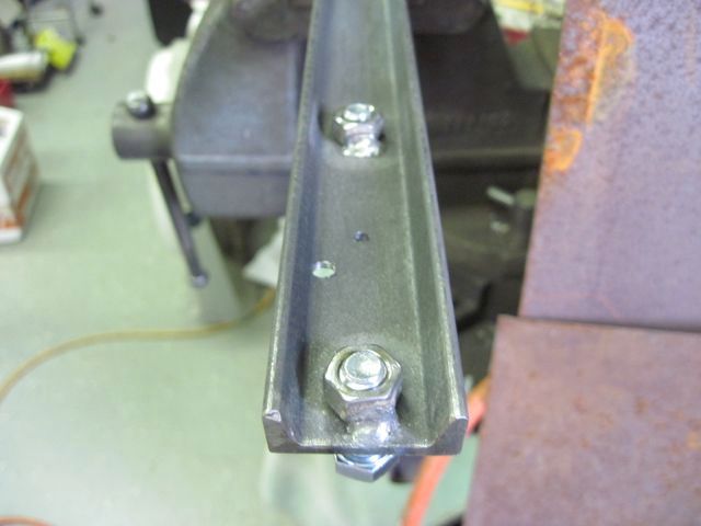
Here they are complete, one for each side, before and after painting:
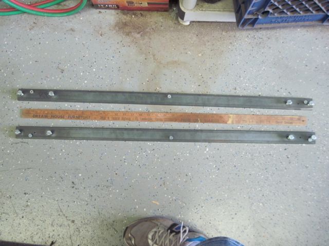
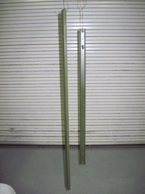
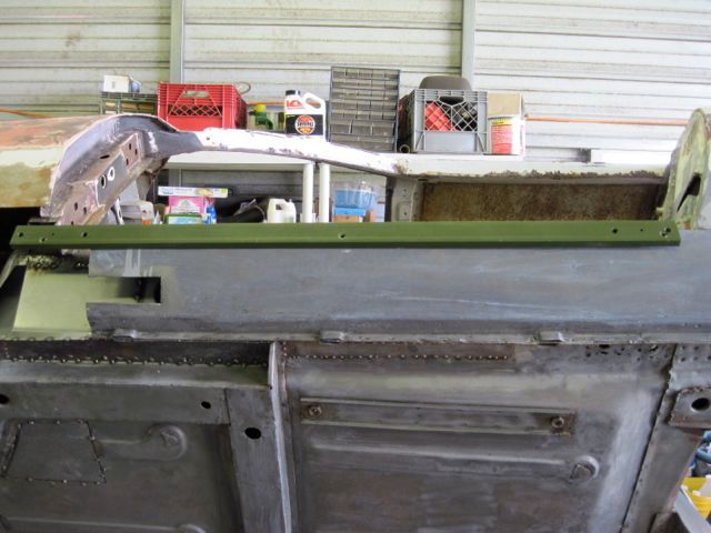
Now, back to where was I? These stiffeners can only be installed with the front of the inner rocker channel open, as mine was thanks to all the rust repairs. Once it is installed, the opening is welded up, and it does not come out again.
Here is the inside view (this pic is the right side, while I’m working on the left; did not get a pic of it):
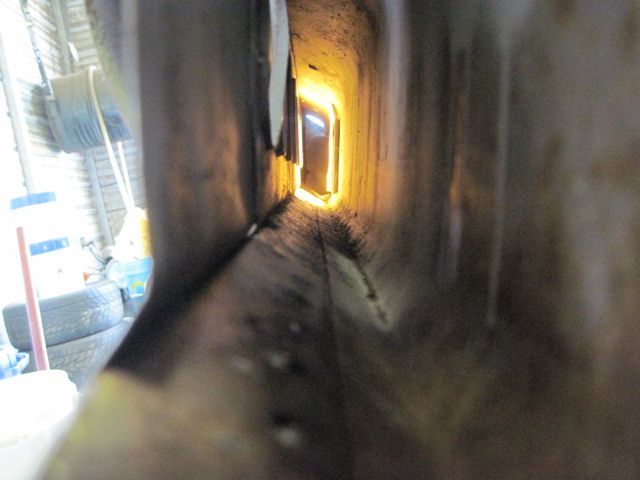
And finally the installation:
Standard disclaimer of liability: I can offer no assurance that this design offers any benefit or meets any specifications, or is suitable for any specific purpose, yada, yada, yada. If anyone chooses to copy it, you do so at your own risk. Nuff said.
Next episode; closing up the rocker and finishing the metal work.

