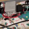
George - thank you for the response - attached is photo of my set up for which I followed your instructions and I am using a relay- now I have more questions.
If I don't use the OEM wiring to supply power to the positive side of the coil, what source should I be using to power the coil?
You say "The wire which previously provided power to the coil (coil's + terminal) can be used to pull-in the relay." If this is the case, this is what i was planning to do and I was asking whether the pink wire or blue/black wire (they are together in a two prong plug) that went into the ballast resistor then from the resistor to the coil would be the right wire to attach to the 86 terminal on the relay - please advise
Similarly, you indicate "The wire which originally supplied the tachometer (coil's neg terminal) will need to be spliced into the green wire circuit (or green with light green stripe) between the coil negative terminal and the Duraspark module. While I don't see this on your wiring diagram that I am following, this can easily be accomplished as I can add a ring terminal to the OEM blue/black wire and connect that to the negative side of the coil - Correct?
Finally, I can't turn the car on now to do any tests - it's all apart and at this point in the restoration, I am cleaning up all the harnesses and adding the Duraspark and a GM 94 AMP alternator.
I look forward to getting your insights on this - Thank you
PANTERA INTERNATIONAL
A DE TOMASO CAR CLUB
Presents the De Tomaso Forums
The On-Line Meeting Place for De Tomaso Owners and Enthusiasts From Around the World
Clicking on the banner will take you to the sponsor's website.


