


click above
The 351C was manufactured in the US for 5 years, in a period of time in which society (supported by US auto manufacturers, yet opposed by the petroleum industry) was seeking to remove lead from gasoline. During the last 3 of those years the 4V version of the 351C was equipped with open chamber heads; these were the Q code engines, the engines we call the "351 Cobra Jet". The majority of the 351C 4V engines manufactured were Cobra Jet versions; the majority of Panteras were equipped with Cobra Jet engines as well. The Cobra Jet engines were equipped with either D1ZE cylinder head castings (1972) having 75.4cc combustion chambers and 8.7:1 static compression or D3ZE cylinder head castings (1973/1974) having 78.4cc combustion chambers and 8.1:1 static compression.
Compression makes a big difference in the way an engine performs, raising the compression ratio is the single most important step to take towards improving the performance of these engines. Raising the compression ratio of any low compression 351C shall increase the engine’s output by about 20 horsepower and improve the engine’s responsiveness. Although this does not sound like a lot of horsepower the amount of snap added to the engine’s performance gives the impression that the horsepower has increased much more than it actually has. The performance most people are looking for from an engine shall only be realized by raising its compression.
To raise the static compression of an engine equipped with open chamber heads usually means (1) replacing the heads with quench chamber heads, (2) installing pop-up dome pistons, or (3) installing flat top pistons (1973/1974), "zero decking" the block, and milling the heads. Most people prefer to install the earlier quench chamber cylinder head castings of 1970 and 1971 (D0AE and D1AE castings). The quench chamber heads are the "easiest" way to raise an engine's static compression; some people also believe the quench chamber heads make more horsepower by virtue of the combustion chamber's shape. In the minds of some people the D1ZE castings are "second class" and the D3ZE castings (equipped with 2V size valves) are "undesirable".
However my personal experience and what I've learned from several folks over the decades has given me a different perspective of the open chamber cylinder head castings, I don't perceive them as second class or undesirable, I don't think owners need to replace them, and in fact they may be throwing away horsepower in doing so. The challenge of raising the compression of an engine equipped with these heads remains however. I would like to propose a fourth method for achieving higher compression, which is to focus on raising the engine's dynamic compression employing a camshaft that closes the intake valve 10° earlier than what is customary.
The purpose of this post is to propose a couple of 351 Cobra Jet engine projects to a dying breed of owners who want to build an engine themselves rather than buying a crate engine or paying someone else to build an engine for them. The projects utilize the OEM block and cylinder head castings. One project utilizes the OEM crankshaft, the other utilizes a crankshaft with a conservative increase in stroke (3.75"). So there's minimal investment in aftermarket parts, however component choices also include forged "round-skirt" racing pistons, a custom ground camshaft, and tappet bore bushings. These choices add about $900 USD to the price of an engine project and have traditionally met with resistance from some owners. My focus is upon building usable street engines that retain factory-like drivability and reliability while releasing the unique potential designed into the factory Cobra Jet (Cleveland 4V) cylinder heads. These are engines appropriate for sports cars like the Pantera, and for street-driven performance cars like Mustangs and Aussie Falcons; they usually attain 100 to 200 more horsepower than their original factory ratings and they operate with vigor over an amazingly wide power band. I don't consider what I do to the engines as "hot-rodding" them but as enabling these amazing engines to achieve the potential built into them. Its tantamount to loosening one's grip on the reigns and giving a race horse its head.
FUEL OCTANE AND COMPRESSION RATIO
The compression ratio of an engine is limited by the octane of the gasoline that shall be used. There are two rating systems for octane being used around the world. Since this is an international forum, it’s important that we are all on the same page. The octane of pump gasoline in Europe, Australia, and most countries of the world is rated using a method named the “Research Octane Number” (or RON). However, the octane of pump gasoline in the US, Canada, and Brazil is rated using the average of the RON rating plus a second rating method called the “Motor Octane Number” (or MON); the formula for the averaged rating is simply (RON + MON) ÷ 2. Fuel rated 95 RON is equivalent to fuel rated 91 using the (RON + MON) ÷ 2 averaged method.
What is not well understood is that 95 octane fuel is the lowest octane fuel available in some European nations, yet the equivalent fuel rated 91 octane in the US and Canada is the HIGHEST octane fuel available in some states; predominantly western states (including California) and Rocky Mountain states. No matter where we are driving in Europe, North America, Australia or New Zealand this 91/95 octane fuel is available to all of us, the car can be driven anywhere or sold to anyone without fuel becoming an issue. For some Europeans it’s the “cheap stuff”, for some folks in the US it’s the “expensive” stuff, and for everyone else it’s a mid-grade fuel. The 1970/1971 versions of the 351C 4V were built to use this fuel off the showroom floor. All of these considerations are factors in my choice to assemble street engines designed for this fuel octane.
An engine’s compression ratio can be understood or defined in three ways:
• By the static compression ratio, which is the total volume above the top piston ring at BDC divided by the total volume above the top piston ring at TDC. This is the most quoted compression ratio, but it is also the least meaningful.
• By the dynamic compression ratio, which is based upon an engine’s effective stroke. The effective stroke begins in the range of 60° to 80° after bottom dead center (ABDC), when the intake valve comes to rest on its seat (is fully closed). This compression ratio is more realistic than static compression, and better for predicting an engine’s anti-knock capabilities. This is the compression ratio engine builders pay attention to. In the "good ol' days" we used to measure this stroke empirically with a camshaft timing wheel and a machinists ruler, today there are "calculators" for doing this, using somewhat complicated mathematic formulas.
• Both the static compression ratio and the dynamic compression ratio "assume" 100% volumetric efficiency (VE). A third method of defining an engine's compression ratio known as the effective compression ratio does not assume 100% VE, it takes into account the density of the air/fuel mixture within the cylinder. Thus effective compression defines a race engine’s compression ratio under wide open throttle conditions, and how it varies with volumetric efficiency and engine speed. This number can be higher or lower than the dynamic compression number, depending upon the intake valve's closing point and the engine's VE at various engine speeds, particularly influenced by "intake charge ram tuning". Street engine's operate 99% of the time at part throttle, therefore this method has no pertinence in building a street engine, I only mention it for the sake of thoroughness ... and to kindle thought.
Although we usually refer to compression ratio in terms of the “static” specification, it’s the “dynamic” compression ratio that more accurately describes the limitation in the amount of compression a motor can tolerate. Based upon the empirical experience of many owners, including myself, the factory Cleveland cylinder heads (iron) can safely tolerate dynamic compression up to 8.0:1, naturally aspirated, carbureted, with full ignition advance, burning 91 octane pump gas (US/Canadian); in fact I know of engines operating just fine at 8.25:1 dynamic compression.
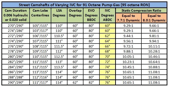
• One method to achieve 8.0:1 dynamic compression ratio is via 11.00:1 static compression with the intake valve closing at 75° ABDC. 11:1 compression is not as big of a deal as some people blow-it-up into being. A cam with 285° intake duration and 113° intake centerline closes the intake valve at 75° ABDC.
• Another route towards achievement of 8.0:1 dynamic compression is via 10.50:1 static compression with the intake valve closing at 70° ABDC. A cam with 280° intake duration and 110° intake centerline closes the intake valve at 70° ABDC.
• A third route towards achievement of 8.0:1 dynamic compression is via 10.04:1 static compression with the intake valve closing at 65° ABDC. A cam with 275° intake duration and 108° intake centerline closes the intake valve at 65° ABDC.
• A fourth route towards achievement of 8.0:1 dynamic compression is via 9.66:1 static compression with the intake valve closing at 60° ABDC. A cam with 270° intake duration and 105° intake centerline closes the intake valve at 60° ABDC.
The point I wish to make from all of this is that an engine having 11.0:1 static compression can operate on the same fuel octane as an engine with 9.66:1 static compression. Conversely an engine having 9.66:1 static compression can make just as much horsepower as an engine having 11.0:1 static compression. In either situation it is merely a matter of camshaft design. The interaction between fuel octane, static compression ratio, and camshaft design must ALWAYS be considered when assembling an engine in order to keep the dynamic compression ratio within the anti-knock capabilities of the engine's cylinder heads.
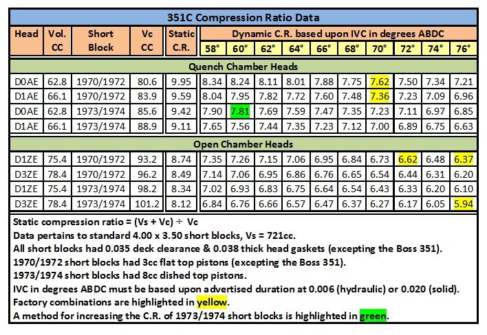
It is my convention to design Cleveland street engines conservatively, for 7.7:1 dynamic compression. By doing so I leave room for variation; variation in assembly, variation in tune, variations in volumetric efficiency, variation in fuel quality, and variation in operating conditions (weather, traffic conditions, engine load, etc). For your comparison, the factory 351 Cleveland engines with the highest static compression ratios, i.e. the 1971 BOSS 351 and the 1970 351 4V, had “nominal” dynamic compression ratios of 7.69:1 and 7.62:1 respectively.
The engine projects I shall propose are designed to operate "comfortably" on 91 octane US/Canadian pump gasoline (same as gasoline rated 95 octane in Europe & Australia). They are designed to achieve 7.7:1 dynamic compression (as per my normal convention) by virtue of balancing when the intake valve closes with the engine's static compression ratio. The dynamic compression ratio is the same whether the engine has 10.0:1 static compression and an intake valve which closes at 70° ABDC, or 9.3:1 static compression and an intake valve which closes at 60° ABDC.
POWER BAND AND HORSEPOWER
The M code version of the 351C 4V was rated for peak horsepower at 5400 rpm whereas the Q code version was rated for peak horsepower at 5800 rpm, which is 400 rpm higher. Both engines utilized cylinder heads with the same size valves and the same size ports, they both utilized camshafts with approximately the same intake duration, they both used intake manifolds of basically the same design, and they both used the same cast iron exhaust manifolds. The engine speed at which peak horsepower occurred rose by 400 rpm by virtue of a camshaft with higher valve lift and a larger carburetor. As we "uncork" the engine further the engine speed at which peak horsepower occurs shall continue to rise, this is the nature of the 4V cylinder heads. The 4V cylinder heads are high port cylinder heads designed in their day to be state-of-the-art NASCAR racing heads, they were significantly tamed for street operation. Peak horsepower of the proposed engines shall occur at approximately 3750 fpm mean piston speed, this is equivalent to 6400 rpm (3.50 stroke) or 6000 rpm (3.75 stroke).
Do not be alarmed by these engines achieving peak horsepower at 6400 rpm! The revised Cobra Jet cams I have designed for this project have no more intake duration than the originals, they are NOT long duration racing cams. We are simply "uncorking" the potential of the engines, allowing them to perform as they were designed to perform. It is not as though they are high rpm engines with no low rpm power, these engines have plenty of low rpm power, peppy throttle response, and good drivability. Factors contributing towards the low rpm performance include good dynamic compression (7.7:1 to 8.0:1), a low-overlap camshaft (60° or less), a dual plane intake manifold, a moderately sized carburetor (750 cfm or less), a carburetor having low speed (part throttle) circuits which are tuned properly, and an ignition calibrated to provide plenty of spark advance at idle (16° to 18°).
The engineers at Ford chose the canted valve cylinder head design for its distinct properties which promote wide flat torque curves. The Cleveland 4V cylinder heads are thus notable for the wide flat torque curves and wide power bands they are capable of creating when assembled accordingly. The 351C with 4V heads is most notable for its tremendous mid-rpm rush of acceleration. However, due to the wide flat torque curve of the Cleveland 4V cylinder head, the power of a 351C simply does not "roll-off" at high rpm like it does with other engines, the engine keeps pulling and pulling, it revs its heart out for you if you ask it to. The engine's ability to accelerate and to rev at high rpm is either frightening, awe inspiring, or intoxicating ... depending upon your personal perspective.
The “typical” engine from which I have extrapolated the data below was equipped with 4V quench chamber heads, flat top pistons, 8.0:1 dynamic compression, 36°/38° total ignition advance, a hydraulic camshaft (typical specs: 275°/285° duration at 0.006, 0.550/0.560 net valve lift, 52° overlap), stiff push rods, and recommended valve springs (Crane, Manley or PAC Racing). Engines with hydraulic roller cams used Crane or Morel tappets, never OEM Ford tappets. Induction and exhaust included a dual plane intake manifold (usually Blue Thunder) with exhaust heat in service, 750 cfm carburetor, and headers with 2” OD primaries (amongst Panteras the Hall GTS headers were predominant). The engines possessed good drivability, and strong mid-range acceleration that doesn't roll-off at high rpm, it just keeps pulling and pulling.
ENGINE DEMAND, CAMSHAFT TIMING and CYLINDER HEAD FLOW
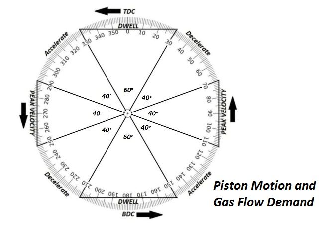
An engine's demand for gas flow is based upon piston motion. A piston begins descending on the intake stroke at about 30° ATDC, it reaches the maximum velocity of its descent at about 70° ATDC, it begins decelerating at about 110° ATDC, and comes almost to a stop at 150° ATDC (30° BBDC). Therefore an engine's demand for gas flow begins accelerating at 30° ATDC and its highest demand for gas flow occurs between 70° and 110°ATDC. There are two criteria therefore that impact our ability to design an induction system to complement these demands:
• An intake lobe centerline of 90° ATDC (half way between 70° and 110°) would be ideal, however such camshaft timing for a street engine would require an intake lobe of only 240° duration. I don't think conventional minds are ready to accept a camshaft having 240° intake duration and an intake centerline of 90°. The small selection of camshaft lobes having 240° duration, none offering very high lift, is another drawback. So for now it is best to time an intake lobe centerline for a street engine's camshaft as early as acceptable, and to use lobes of longer duration in which there is a wider selection of choices. An intake lobe centerline varying from 103° to 113° is acceptable, but such camshaft timing shall be out of sync with piston motion by 13° to 23°!
• Since camshaft timing is not synchronized perfectly with piston motion the more air flow the cylinder head can provide throughout the entire range of valve opening is important, NEVER just the peak number. After 60° of duration the valve must be lifted open high enough, and the cylinder head must flow sufficiently, to meet the needs of the accelerating piston. Mid-lift flow after 100° of duration capable of meeting an engine's peak demand is significantly important. If a cylinder is filled with air/fuel almost 100% (or more) by 30° ABDC there is little to be gained by ram tuning.
ARE THE OPEN COMBUSTION CHAMBER 4V CYLINDER HEADS REALLY SECOND CLASS?
Quench
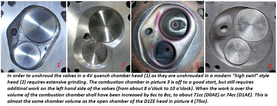
The flow coefficient of a shrouded valve is worse than the flow coefficient of an unshrouded valve. Valve shrouding is a big issue in cylinder head design. Cleveland valves unshroud themselves as they open by virtue of the canted valve geometry, but the low lift flow coefficients of all "quench chamber" Cleveland cylinder heads are significantly impacted by shrouding. The issue of shrouding is one of the reasons why the modern “Yates high swirl” combustion chambers are superior to earlier quench designs; the high swirl chambers do a better job of unshrouding the valves while promoting a "specific" type of turbulence within the combustion chamber known as swirl (diffusion of the air/fuel mixture and funneling of the exhaust gas are also promoted).
There is a belief system within hot rodding that "quench" makes power. While this is true for some cylinder heads it is not true for all. Some cylinder heads shield a significant portion of the fuel/air mixture within the cylinder from the flame front. Of course unburned fuel does not contribute to making power. The idea behind "narrow quench space" in those heads is to squeeze as much air/fuel mixture as possible out of the quench space and into the actual combustion chamber where it is no longer shielded from the flame front, where it shall be ignited and thus contribute to making power. Combustion chambers with lots of quench are an inherently faulty design, and the convention of narrowing the piston clearance in the quench area is a "means" for extracting more horsepower from engines equipped with such cylinder heads. We are of course talking about the wedge chambers of small block Chevys and small block Fords.
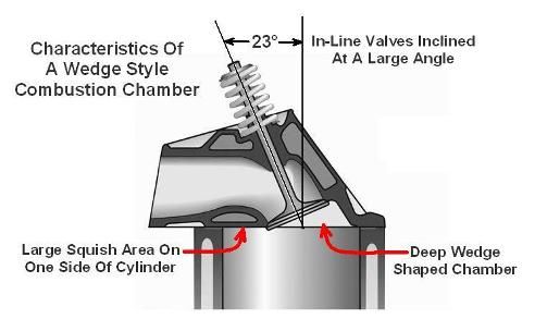
The broad and shallow Cleveland chambers, resulting from the low valve angles, are superior to wedge chambers. Open chamber versions of the Cleveland head obviously have no quench areas to shield any portion of the combustion chamber from the flame front. There isn't enough quench area to make a detrimental impact upon horsepower in the quench chamber versions of the Cleveland cylinder head either; no part of the combustion area is significantly hidden from the flame front, minimizing quench clearance is not needed to expose otherwise unburned air/fuel mixture. The Cleveland cylinder head creates turbulence within the combustion chamber by virtue of the chamber's shallowness. I know from experience the open chamber heads resist detonation equally as well as the quench chamber heads, both versions can operate at the same compression ratios.
So how does the performance of quench chamber and open chamber heads differ?
The small amount of quench surrounding the combustion chambers of the Cleveland quench heads is intended to squeeze the fuel and air mixture around the periphery of the cylinder towards the middle thus improving low rpm power (faster combustion at low rpm), but Ford engineering stated that design didn’t contribute significantly to mid or high rpm power. Unfortunately the chamber design of those heads shrouds the valves extensively, especially at low valve lift. Open chambers corrected this problem, which is a far more important aspect; they improved the cylinder head’s low lift flow coefficient via unshrouding the valves. The low lift air flow of the intake port of an open chamber 4V cylinder head exceeds the low lift air flow of the intake port of a quench chamber 4V cylinder head by at least 25 cfm from 0.100" valve lift to 0.300" valve lift.
The D1ZE open chamber cylinder head went into production about May 1971. Ford engineering promoted the D1ZE cylinder head for racing in the Off Highway Parts manual of 1972. They claimed the heads flowed better, but they also advised using the D1ZE heads would require the development of custom pop-up dome pistons to raise compression. Ford engineering was no longer as closely involved with the race teams as it had been, because Ford pulled financial support from the entirety of their racing operation at the end of the 1970 season. The Off Highway Parts operation was shut-down too, in February 1973. Development of the open chamber heads for racing fell by the way-side.
I have known people racing the 351C in competition who have preferred the open chamber D3ZE cylinder heads as far back as the 1980s. Each of them had developed their own custom pop-up dome piston to build compression. They could have used any factory cylinder head they chose, and they were adamant that their race car was fastest using the D3ZE cylinder heads.
Valve Sizing
While big valves offer improvements in performance, there is such a thing as too big, the issue is again related to the subject of valve shrouding. The optimum balance between valve size and valve shrouding is considered today to be about 53% of the bore. Big valves are beneficial, because for a given amount of lift a bigger valve opens more curtain area ... so the big valve exposes more curtain area faster. But if the valve is so big that shrouding becomes an issue then that curtain area will not be realized. You're fooling yourself if you think a big valve is always better, even when its shrouded. BUT (that's a big but) a valve is only capable of allowing a certain throat diameter. And a certain throat diameter is only capable of supporting a certain bore and stroke up to a certain rpm (I calculate maximum throat as valve diameter minus 0.3"). So the first question is how much throat does your engine need to avoid sonic choke?
The Cleveland cylinder heads were first produced with 2.23 intake valves (1969 Boss 302). The intake valves were downsized to 2.19 in 1970, that valve was still too big for a 4.00 bore, but they were planning to use 4.080 bores in NASCAR (the Chevy 396 also had a 2.19 intake valve, its bore was 4.094). The intake and exhaust valves of the production head (street engines) were downsized again in 1973; some will disagree, but I believe the engineers at Ford were still learning and each change was intended to improve the engine.
Those last 4V cylinder heads, the D3ZE castings, down-sized the valves to the size of 2V valves (2.05 intake valves and 1.65 exhaust valves); these 4V castings had combustion chambers which were for the first time a perfect 4 inch diameter circle, and the 2V sized valves actually fit within that 4" diameter combustion chamber ... the result was of course less shrouding and therefore improved air flow. The D3ZE cylinder heads were in fact the first and only factory 4V heads truly designed for a 4.00 inch bore. A 2.05 valve should be capable of being ported to 1.75 throat. This will supply a 357 at 7300 rpm.
Remembering the 53% rule, the 2.05 inch diameter 2V intake valve of the D3ZE cylinder head could have been upgraded to a 2.12 valve, which is certainly a "big valve" for a 4" bore but one that is not "over-sized". A 2.12 valve (1.82 throat) will supply a 357 at 7900 rpm. This valve is all you're gonna stuff into a 4" bore without getting into shrouding. So here's the point where we achieve the best curtain area and largest throat; anything larger is a compromise between throat diameter and curtain area. If we select a larger valve it should be because we need the increased throat size, and are willing to sacrifice air flow to achieve a higher sonic choke point. However, even with a bigger intake valve the D3ZE heads would have still had one down side; like the D1ZE heads, their 78.4cc combustion chamber volume made it difficult to build compression with flat top pistons.
NASCAR lowered the displacement limit to 358 cubic inches as of the 1974 season (4.030 bores). In spite of the reduction in bore diameter the NASCAR teams continued to use 2.19 intake valves (capable of being ported to 1.9 throat) which supplied a 358 up to 8500 rpm. The NASCAR teams needed this rpm capacity, but there was a price to pay for stuffing that much throat capacity into a 4" bore.
Port Height
At this point some people may ask, if open combustion chambers and smaller valves are better, why not use US 351 2V heads or Australian 351C heads?
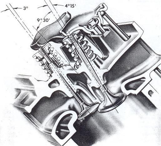
Canted valve cylinder heads have several advantages, among them is (1) the ability to use larger valves than what is possible with a “wedge” head, (2) smaller valve angles promote higher thermal efficiency via a broad and shallow combustion chamber, (3) the push rods are angled apart eliminating the pinch point where the intake port passes between them, and (4) the valves “unshroud” themselves as they open. There is however one drawback to cylinder heads having “small” valve angles, for a given port height the angle at which the intake port intersects the valve pocket is less favorable. Therefore canted valve cylinder heads with small valve angles NEED higher ports to achieve an interface angle between port and valve pocket equivalent to the interface angle of a wedge head, and thus to realize the air flow performance they are capable of achieving. The Cleveland 2V intake port is the same height as the intake port of a small block Ford wedge cylinder head, and thus at a disadvantage in this aspect. The "low port" (i.e. 2V) Cleveland cylinder heads are decent heads, many people are quite satisfied with their performance, but they do not have the air flow capabilities of the high port (i.e. 4V) Cleveland cylinder heads. The Cleveland 4V intake port is a 1/2 inch higher and the ramp cast into the entrance of the 4V intake port enables it to behave as an even higher port; port height is precisely why the 4V heads flow better than the 2V heads.
Port Size
You may next ask isn’t the 4V intake port too large?
The 4V intake port is physically large at the inlet, but it becomes quite a bit smaller further inside. In spite of the large inlet the port's average cross-section is only 2.9 square inches, and its volume is 242cc. It is tuned for about 6400 rpm (3750 FPM mean piston speed). If you compare the average cross-sectional area of the 4V intake port to the average cross-sectional area of the intake ports of several popular aftermarket SBF or SBC cylinder heads, tuned for about 6000 rpm, you shall find that rumors of its “largeness” are exaggerated. If you want to argue that 6400 rpm is too high for a street engine, that is of course a valid argument ... but only in a world conditioned to thinking that anything more than 6000 rpm is too much. That was not the prevalent perception in 1970. In the case of the 351 Cleveland peak horsepower can be attained at that rpm while maintaining good low rpm performance, and without great expense. The Cleveland Ford's wide power band and willingness to rev is an intoxicating discovery for many owners.
The 4V cylinder head was designed to make the intake valve size the limit to gas flow, the intake ports were logically designed to support the capabilities of the intake valve. The maximum throat diameter of a 2.19 intake valve is 1.9 inches; sonic choke at that throat diameter occurs at an average piston speed of 5000 fpm; equivalent to 8600 rpm in an engine having a 3.50” stroke. It has been long held that the maximum average piston speed for an endurance racing engine is about 5000 FPM; the coincidence between these two parameters was not accidental.
The 4V port gas velocities are indeed on the low side of modern standards, but not tremendously so. Ford was paying close attention to gas velocities within the ports by the time the Cleveland cylinder heads were being developed. Careful attention was paid to avoid sonic choke at peak piston acceleration. Piston speed is the source of gas velocity; whenever the cross-sectional area of an intake port is reduced to "artificially" increase gas velocity beyond that which is the result of piston speed, that intake port becomes a restriction to gas flow at high rpm. The 4V intake port was sized to be big enough to avoid becoming a high rpm restriction to gas flow, but it was also sized to avoid reducing gas velocity more so than what is necessary. Thus in spite of its high rpm capabilities the 4V intake port remained viable as the intake port for a 351 cubic inch street engine. This is what was meant when back in 1970 Ford engineers described the ports of the 4V cylinder heads as having been “carefully” sized. “Ram tuning” however was not the “hot topic” in 1970 as it became in the 1990s. The port gas velocity goals in that era were simply not as vigorous as they are today; the 4V Cleveland intake port was however designed to operate on the “high side” of those older standards. It is my understanding that race engine designers target about 325 fps in a modern port, whereas the Cleveland port “cleaned-up” for racing operated at about 305 fps. In order to operate at today’s higher gas velocities a modern race port must be straighter, have constant cross section and shape, and have a very large short-side radius (it must be a higher port).
One of the challenges in induction system design is enabling the air/fuel mixture to transition from the intake port to the intake valve pocket in a manner that does not impede flow. As gas velocity within the intake port increases it becomes more difficult for the fuel/air mixture to negotiate the short turn radius from the intake port into the intake valve pocket. There are three methods in which ports are tailored to accomplish this. The first is to raise the port in order to make the short turn radius larger; the second method is to increase the size of the valve pocket and the size of the port at the valve pocket entrance in order to reduce gas velocity as it negotiates the short turn radius, the third method is to adjust the average cross-section of the port and therefore adjust the average port velocity. These parameters are interactive, and they are influenced by factors such as engine height limitations, engine output expectations, and the engine's power band. It is my experience that the Cleveland 4V intake port is a good compromise of air flow, port height, and engine power band; any cylinder head claiming to have equal or better gas flow AND higher gas velocity has a higher port entrance, or a dropped combustion chamber, or both.
The inlet of the 4V intake port is large because there is a ramp built into the floor of the port. The port floor was lowered about 1/2" to accommodate the ramp, adding about 15cc to the port's volume in the process. The ramp was put there to improve air flow in lieu of raising the port any further. NASCAR had rules back when the Cleveland was designed that prevented using cylinder heads that resulted in engines too tall for production automobiles. This is the same ramp design that was employed in the medium rise FE cylinder heads, after NASCAR had outlawed the high rise FE cylinder heads. The ramp actually works, it does indeed increase airflow, unfortunately it also results in a port having an irregular shape. The irregular shape does not seem to hinder performance at engine speeds below 7000 rpm however. Of course I would prefer a 1/4 inch higher intake port without all the tricks of the 4V intake port, one that is consistent in shape and cross-section, and about 7% smaller in average cross sectional area; that more or less describes the intake port of the Ford Motorsport M-6049-B351 cylinder head of 1985. But in the absence of that option amongst the factory iron heads I prefer the 4V intake port with its tricks over the lower 2V port.
I have found 4 common themes amongst owners who are unhappy with the lower rpm performance of the 4V head equipped Cleveland engines in their car: (1) insufficient compression, (2) too much cam, (3) a poorly operating or poorly calibrated carburetor, or (4) not enough gear. It is not commonly understood in the hot rod community that engines with large canted valve cylinder heads cannot tolerate as much overlap as other engines if low rpm performance and drivability are desired. When it comes to the 351 Cleveland everyone’s first reaction is to blame the intake port for being too large.
Summary
The engineering that culminated in the 4V Cleveland cylinder head was the result of extensive research, testing, and the experience of professional engineers and championship winning racing teams. The 4V Cleveland cylinder head was a landmark development, its engineering continues to be the foundation of OHV racing cylinder heads to this day.
There are no bad production Cleveland heads, they all have their merits. They all share the same excellent "shallow poly-angle" combustion chamber design and canted-valve geometry. The 2V (low port) heads are tuned for lower rpm, they can be fitted with 2.12 intake valves (as advised for the D3ZE heads), and their open combustion chambers have the advantages of improved low-lift air flow. Although their air flow flattens out at 0.500" lift due to their "low port" design, they are still capable of supporting over 400 horsepower. The D0AE and D1AE quench chamber 4V heads offer excellent air flow capabilities due to their big valves and high ports, their reduced chamber volumes make it easier to achieve 10:1 static compression with a standard displacement engine, and the small amount of quench provides good low rpm torque. The D1ZE open chamber 4V head castings have the same big valves and high ports, but they trade the low rpm torque of the quench chamber heads for improved low-lift air flow at ALL rpm. The D3ZE castings have the same port height as all 4V heads, they have the open chambers which promote better low-lift air flow, and they have chambers and valves sized properly for a 4" bore thus un-shrouding the valves even better than the D1ZE heads. The 4V heads which some people consider "undesirable" are possibly the best factory "iron" Cleveland head produced for the standard 4.00 bores of the production engine. They are not perfect by any means, but they are in most ways the best choice amongst all the factory castings from the US or Australia ... their one drawback being the 78.4cc volume of the combustion chambers. Milled the maximum amount (0.060") their chamber volumes can be reduced to 66cc (same as the D1AE quench chamber heads), but I'll explain a better way to resolve this issue below.
THE REVISED COBRA JET CAMSHAFT
The original Cobra Jet camshaft combined a race cam exhaust lobe for good high rpm performance along with a short duration intake lobe for good drivability, the specs were 270°/290°. The camshaft had low overlap (46°) which also contributed to good low rpm power and drivability. It opened the valves quite a bit for a street cam designed in 1966 (the original application was the 390 GT), the lift specs were 0.481/0.490.
I've revised the Cobra Jet camshaft lobe centerlines, setting them at 105°/115°. This has the effect of narrowing the lobe centerline separation angles to 110°, and timing the camshafts 5° advanced. That's fairly standard camshaft timing for this day and age. Be assured I haven't done anything strange or wonky. Thus reconfigured the intake valve closes at 60° ABDC, which is 10° to 16° earlier depending upon which camshaft timing you are comparing it to. The purpose behind this change is to build good dynamic compression with lower static compression. Narrowing the lobe centerline separation angle increased overlap, which is now 60°. This is very close to the same overlap as the original Boss 351; its not excessive but you wouldn't want any more than that for a street engine. The overlap period is now centered very well around top dead center, and it is within the dwell period at TDC. This serves to minimize the effect overlap has upon the engine's low rpm performance and drivability. The exhaust valve opens early enough to encourage high rpm performance even with a quietly muffled exhaust system. The intake valve begins opening 10° to 16° earlier and reaches full open 10° to 16° earlier, this makes more horsepower. Thus the revised Cobra Jet camshaft has all the benefits of an aftermarket narrow LSA camshaft without any of the typical drawbacks.
Unfortunately camshafts ground to this specification are not available off-the-shelf, they shall have to be custom ordered. I shall provide specifications for moderate lift hydraulic cams, high lift hydraulic cams, and high lift solid tappet cams, for either flat tappets or roller tappets (something for everyone) in another section below. When combining these cams with the factory iron heads I recommend keeping the static compression ratio within the range of 9.05:1 to 9.65:1, with a recommended target of 9.3:1 static compression or 7.7:1 dynamic compression.
The Cobra Jet engines, equipped with open chamber 4V heads and my revised version of the Cobra Jet camshaft, shall achieve higher output than engines equipped with quench chamber 4V heads due to (1) improved air flow at low valve lift as a result of unshrouding the valves and (2) due to opening the intake valve significantly earlier due to moving the intake lobe centerline to 105° ATDC.

Continued Below
.