

Flat Tappet Camshafts, Tappets, and Springs
These camshafts are flat tappet camshafts. Camshafts number 1 and number 2 are both hydraulic flat tappet cams differing mainly in the amount of valve lift they provide. Camshaft number 3 is a solid flat tappet street cam.
In order to find a high-lift hydraulic flat tappet lobe in the Bullet Cams catalog for the intake valve of camshaft number 2 it was necessary to stray a bit from the 270°/290° duration of the Cobra Jet cam, I ended up using lobes of 275°/286° duration; therefore the overlap period is not as well centered within the dwell period at TDC, but the amount of overlap is unchanged. The EVO, IVC and LSA also remain unchanged.
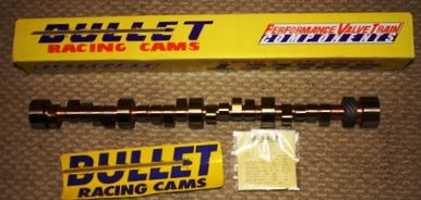
(1) Custom hydraulic flat tappet cam ground by Bullet Cams (lobes H270/306 and H290/312), spec: 270°/290° duration @ 0.006, 222°/240° duration @ 0.050, 0.521/0.531 net lift, 105°/115° lobe centerlines, 110° lsa, 60° overlap, EVO = 80°, IVC = 60°. Speed Pro HT900 hydraulic flat tappets.
(2) Custom hydraulic flat tappet cam ground by Bullet Cams (lobes HF275/328 and H286/328), spec: 275°/286° duration @ 0.006, 223°/230° duration @ 0.050, 0.559/0.559 net lift, 103°/117° lobe centerlines, 110° lsa, 60.5° overlap, EVO = 81°, IVC = 60.5°. Speed Pro HT900 hydraulic flat tappets.
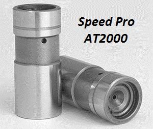
(3) Custom solid flat tappet cam ground by Bullet Cams (lobes FF271/333 and F292/334), spec: 271°/292° duration @ 0.020, 236°/256° duration @ 0.050, 0.548/0.545 net lift (0.028/0.033 lash), 105°/115° lobe centerlines, 110° lsa, 61.5° overlap, EVO = 81°, IVC = 60.5°. Speed Pro AT2000 or Crower Cams 66915X980-16P solid flat tappets. These are Boss 351 style tappets with an internal metering plate system for controlling the amount of oil flowing to the valve train.
When ordering a flat tappet cam you must specify to the cam grinder that the camshaft (a) should be ground on a best quality iron cam core, (b) it should be ground with a guaranteed 0.002" lobe taper, (c) it should receive their best quality hardening treatment (nitriding), and (d) it should receive their best quality lobe polishing.
Note:
Hydraulic Flat Tappets - I am always careful to use and recommend parts of known quality, and which are manufactured in North America or Australia. I have used Speed Pro tappets (originally manufactured in the US by Johnson) since I was a young man. Speed Pro is now part of the Federal Mogul group of businesses, they acquire parts globally, they do not advertise where the tappets are manufactured or which company manufactures them. Therefore I am unsure if they are made to the same high quality they once were. Tappets manufactured by Johnson can be identified by the "smooth waist" (no ridges) and the single groove machined above the waist, see the picture below.
One aspect in which the performance of modern hydraulic tappets has suffered is the tappet's bleed down rate. Some cam grinders & engine building businesses are capable of checking the bleed down rate prior to shipping them to you, the extra cost for this would be worthwhile considering.
One possible valve spring for the flat tappet cams is Crane 99839, it is a single valve spring plus damper, 1.50 diameter, 354 pounds per inch spring rate. When installing this valve spring please ignore the factory specs, and adhere to these: 1.82 installed height, 114 lbs. seated force, 0.590” maximum lift.
Another possible valve spring for the flat tappet cams is PAC Racing 1900, it is a single valve spring plus damper, 1.50 diameter, 376 pounds per inch spring rate. When installing this valve spring please ignore the factory specs, and adhere to these: 1.82 installed height, 120 lbs. seated force, 0.605” maximum lift.
Roller Tappet Camshafts, Tappets, and Spring
These camshafts are roller tappet camshafts. Camshafts number 1 and number 2 are both hydraulic roller cams, only differing in the amount of valve lift they provide; camshafts number 3 and number 4 are solid roller street cams.
Camshaft number 4 intentionally strays a bit from the 270°/290° duration of the Cobra Jet cam, in order to achieve a "super hot" street cam. I ended up using lobes of 275°/284° duration; therefore the overlap period is not as well centered within the dwell period at TDC, but the amount of overlap is unchanged. The EVO, IVC and LSA also remain unchanged. This camshaft pushes the Manley 221432 valve spring close to the limits of its maximum rated valve lift.
(1) Custom hydraulic roller tappet cam ground by Bullet Cams (lobes HR270/313 and HR291/312), spec: 270°/291° duration @ 0.006, 218°/238° duration @ 0.050, 0.533/0.531 net lift, 105°/115° lobe centerlines, 110° lsa, 60.5° overlap, EVO = 80.5°, IVC = 60°. Crane 36532-16 or Morel 5323 hydraulic roller tappets.
(2) Custom hydraulic roller tappet cam ground by Bullet Cams (lobes HR270/3533 and HR291/356), spec: 270°/291° duration @ 0.006, 216°/236° duration @ 0.050, 0.603/0.607 net lift, 105°/115° lobe centerlines, 110° lsa, 60.5° overlap, EVO = 80.5°, IVC = 60°. Crane 36532-16 or Morel 5323 hydraulic roller tappets.
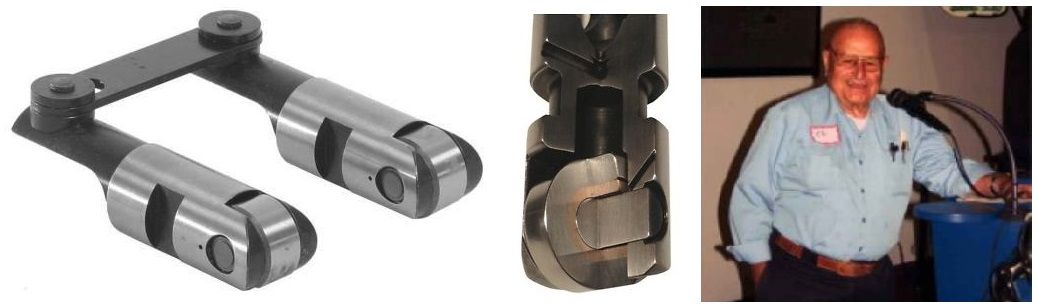
(3) Custom solid roller tappet cam ground by Bullet Cams (lobes R270/363 and R291/363), spec: 270°/291° duration @ 0.020, 237°/255° duration @ 0.050, 0.607/0.599 net lift (0.021/0.029 lash), 105°/115° lobe centerlines, 110° lsa, 60.5° overlap, EVO = 80.5°, IVC = 60°. Isky 3972-RHEZ solid roller tappets. The Isky tappets roll on bushings rather than needle bearings, and they are force lubricated rather than splash lubricated. Tappet bore bushings with 1/16" orifices are a necessity when utilizing solid roller tappets.
(4) Custom solid roller tappet cam ground by Bullet Cams (lobes R275/3685 and R284/370), spec: 275°/284° duration @ 0.020, 240°/248° duration @ 0.050, 0.616/0.619 net lift (0.022/0.021 lash), 103°/117° lobe centerlines, 110° lsa, 59.5° overlap, EVO = 79°, IVC = 60.5°. Isky 3972-RHEZ solid roller tappets. The Isky tappets roll on bushings rather than needle bearings, and they are force lubricated rather than splash lubricated. Tappet bore bushings with 1/16" orifices are a necessity when utilizing solid roller tappets.
When ordering a roller cam you must specify to the cam grinder that the camshaft should be ground on a core manufactured from a material which is compatible with standard OEM distributor gears (selectively austempered ductile iron) or compatible with commercially available steel distributor gears. The intention of these instructions is to avoid the use of a bronze distributor gear, due to the rapid wear rate, and due to the fine bronze particles they pollute the engine with.
If the roller cam core requires a steel distributor gear, steel distributor gears for the 351C are available from Crane Cams and Ford Racing. Crane 52970-1 is the gear for 0.500” distributor shafts; Crane 52971-1 is the gear for 0.531” distributor shafts. The gear for 0.531” shafts is also available via Ford Racing Performance Parts under part number M-12390-J. TRITEC Seal (of Swartz Creek, Michigan) has recently introduced a polymer composite distributor gear for the 351C, p.n. PP3734-BB-531. The gear is supposedly compatible with any camshaft core material, and would make a good solution for owners whose engine is currently equipped with a bronze gear.
One final word of caution regarding distributor gears, they should fit tightly on the distributor shaft, they should require a hand press (pin press) to remove and install. Some aftermarket gears do not fit tight enough, some actually slide off & on without any effort. If the gear is not tight enough on the shaft the gear's roll pin shall shear.
Note:
Hydraulic Roller Tappets - The Ford 5.0 HO hydraulic roller tappets have been problematic in 351C applications and are therefore not recommended. They are known to collapse prematurely at high rpm, limiting the high rpm performance of the engine. There are two possible reasons for this: (1) The 351C valve train is heavier, it utilizes higher valve spring forces, and its geometry and splayed push rods subject a tappet to side thrust forces greater than the forces the 5.0 HO tappet has been designed to endure. These forces may distort the tappet body, upsetting critical internal clearances, and lead to premature collapse. It is critical that the body of a high performance hydraulic roller tappet is made sturdy enough to prevent its distortion even when subjected to higher valve spring forces and higher engine speeds. (2) The waist machined into the center of the 5.0 HO tappet is too high, it has been found to rise above the top of the tappet bore at maximum lift and dump the engine’s oil pressure in some 351C blocks, loss of oil pressure will also cause the tappet to collapse. The aftermarket hydraulic roller tappets sold by Crane Cams and Morel are known to operate reliably in Cleveland applications. The waists machined into the center of these tappets do not rise above the top of the tappet bores at maximum lift, and the tappet bodies are thicker and therefore resist distortion (with the penalty of increased weight).
A valve spring for the roller cams is Manley Nextek 221432, it is a dual valve spring plus damper, 1.53 diameter, 435 pounds per inch spring rate. When installing this valve spring please adhere to the manufacturer's specifications: 1.90 installed height, 150 lbs. seated force, 0.630” maximum lift.
If the Manley spring is installed at a height of 1.82 (the standard 351C height) then its maximum lift shall be reduced to 0.550.
Lubrication
• Install tappet bore bushings with 1/16" orifices, a do-it-yourself installation kit is available from Wydendorf Machine for a reasonable price.
• Restrict the oil to all 5 cam bearings; this requires 5 restrictors, which in turn requires two Moroso restrictor kits because each kit only contains four restrictors. The restrictor for cam bearing number 1 is installed differently than the other four. It must be installed deeply within the bearing passage, above the horizontal main oil passage, so that it is positioned between the main passage and the cam bearing. If the restrictor is not installed deep enough, it would restrict oil to main bearing number 1 of the crankshaft. The large restrictors included in the Moroso kits are not used.
• Install fully grooved main bearings. To acquire fully grooved main bearings may require using the upper shells from two sets of main bearings. This provides oil to the rod bearings throughout 360° of crankshaft rotation.
• Install an Aviaid or comparable high volume road race Pantera oil pan.
• The standard oil pump provides plenty of lubrication once tappet bore bushings are installed. The standard pump was actually a high volume pump, it had taller rotors and pumped more oil than the pumps found in Ford's other V8 engines.
• Motorcraft and Wix sell the best filters.
• The final component of the lubrication system is the oil itself. Valvoline VR1, either petroleum based or synthetic, is recommended. No additives. Use 20W50 if the engine has never been rebuilt (20W40 was the original specified oil). Use 10W30 if the engine has been rebuilt.
With these modification you can expect 80 psi cold oil pressure, and hot oil pressure should conform to Ford's specification, which is 60 psi (+/- 10 psi) by 2000 rpm; the hot oil pressure will usually be above 60 psi, it will not "droop" at higher rpm either.
Ultra-low viscosity oils (0W or 5W) can be used under the following conditions: (1) The crankshaft journals and bearing saddles must be machined to a higher level of quality than they were originally machined back in the 1970s. Taper must be less, and concentricity must be better. (2) Tappet bore bushings must be installed. (3) Use 3/4 grooved main bearings (from King Bearing) instead of fully grooved main bearings. Keep in mind hydraulic tappets may not operate properly with these low viscosity motor oils.
There is an ideal clearance in regards to optimizing a bearing's load capacity, it shall be approximately 0.001" per inch of journal diameter, but the precise clearance shall vary from engine to engine. It’s better to have more clearance than optimum than it is to have less clearance than optimum. As a bearing's clearance is reduced to less than optimum its load bearing capability rapidly decreases, whereas when a bearing's clearance is increased beyond optimum its load bearing capability decreases much more gradually. The load bearing capability of a bearing is only one of the properties affected by the bearing’s clearance. When clearances are tightened-up less oil flows into those clearances and therefore the bearings run hotter, because the oil not only lubricates the bearings, it cools the bearings as well. Here again, more clearance than optimum is better than less clearance. If bearing clearances are reduced to a degree less than those recommended above then bearing temperatures shall increase. Under these conditions consider the use of synthetic motor oil a necessity due to the superior high temperature properties of synthetic oil.
Cylinder Head and Valve Train Preparation
The work detailed below in items 1 and 2 are optional, but recommended. This moderate amount of work can make a big difference in cylinder head performance. Perform this work before refurbishing the guides and the valve seats.
(1) Valve Pockets
Clean up the valve pockets, remove casting lines and rough spots, and center the pockets on the valve guides if any aren’t centered. Smooth the guides when needed. As is true for any cylinder head, you want a smooth, well blended transition from the valve pocket to the throat, a "rounded" throat, a nice, smooth, well blended transition from the throat to the valve seat, and from the valve seat into the combustion chamber. Open the throats to the diameter specified for your application. The valve seats are normally recessed a bit, and there shall be sharp edges or “lips” around the valve seats. These “lips” must be knocked down, so that the transition from the valve seat into the combustion chamber is smooth, no sharp edges, no steps, no lips.
(2) Exhaust Ports
The 351C 4V cylinder heads have flat roofs in the exhaust valve pockets, bumps in the roofs of the exhaust ports, and port floors which “fall away” as they approach the exhaust flange. These features were placed in the exhaust ports to encourage exhaust gases to flow “downward” into cast iron exhaust manifolds which hug the engine block closely. These features are not needed if the header primaries exit straight-out from the head as the Pantera exhaust does. The exhaust valve pocket roofs should be rounded, given a typical basin shape. The bump in the exhaust port roof should be ground away.
The port floors can be filled-in (brazed) where they fall away, or commercially available “tongues” can be installed to achieve the same thing. In the case of the D1ZE cylinder head (1.71 exhaust valves) the port floor should filled-in 0.40”, leaving an exhaust port opening of approximately 2.78 square inches (1.75 x 1.60). In the case of the D3ZE cylinder head (1.65 exhaust valves) the port floor should be filled-in 0.50”, leaving an exhaust port opening of approximately 2.59 square inches (1.75 x 1.50).
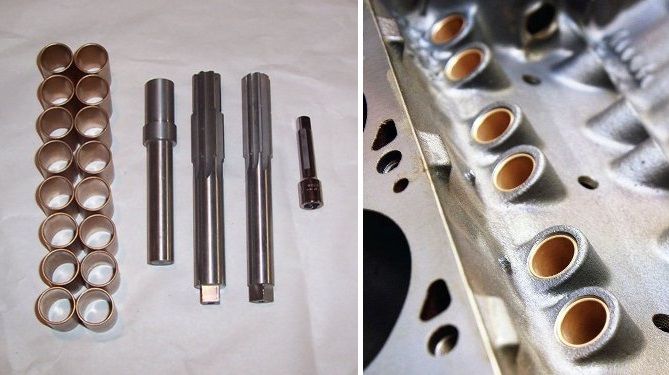
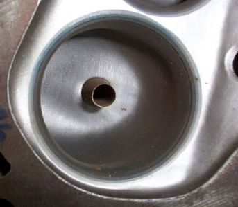
(3) Valve Guides
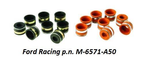
The valve guides should be repaired with bronze guide inserts. Bronze is a good material for the stems of stainless steel valves, and more durable than the original iron of the cylinder head casting. Valve guide to valve stem clearance should be 0.0010 – 0.0020 for the intake valves, and 0.0015 – 0.0025 for the exhaust valves. The top of the valve guides should be machined to 0.530 diameter to allow the installation of spring loaded elastomer valve stem seals such as Ford Racing Parts M-6571-A50 or Manley 24045-8.
(4) Valve Seats
Valve seats should be refurbished with what was once called a three-angle valve job, but today such work is often called valve seat profiling. The valve seat angle should be 45°, the intake valve seat width should be no less than 0.060, and the exhaust valve seat width no less than 0.080. Most often the person performing the valve seat work should only have to “kiss” the seats with the grinding tools to clean them up and size them properly; normally any “major” removal of metal is unwanted and unnecessary. The exception however is the intake valve seats for the D3ZE cylinder heads, adjusting the diameter of the seats for a larger valve will take a little bit more than a "kiss" with the grinding stone.
(5) Valve Spring Installation
Titanium 10° spring retainers are recommended for intake valves. Chromoly 10° spring retainers are recommended for exhaust valves, but using titanium spring retainers for the exhaust valves is OK if the extra expense is in your budget. They should be purchased from the spring manufacturer to complement their spring.
The combined weight of the exhaust valve and the exhaust valve spring retainer must always be LESS than the combined weight of the intake valve and the intake valve spring retainer. You want the intake valves to float first at high rpm thus limiting engine rpm before the exhaust valves float. Floating exhaust valves are to be avoided because the exhaust valves may hit the pistons when they float.
Steel valve spring cups are recommended because they keep the bottom of the spring precisely positioned, preventing it from walking; this will require machining the spring seats for the cup. There is some confusion at Crane regarding which spring cup to use for their 99839 flat tappet spring, the proper cup is p.n. 99455.
Typical of valve springs designed for roller cams, the Manley valve spring’s 1.90 installed height is 0.080 greater than the original dimension; it shall require the use of valves with 0.100” longer stems or further machining the valve spring seats. Utilizing valves with longer stems shall impact the rocker arm geometry, but so do high lift camshafts. You should experiment with both a standard length valve, a longer valve, and your intended rocker arms before deciding which route shall best achieve proper rocker arm geometry, because once the spring seats are machined there’s no turning back. Shim kits for adjusting rocker arm height are readily available. Raising the rocker arm a small amount with shims is much easier than lowering the rocker arm. Experimenting with rocker arm geometry can be performed with the heads removed from the engine, on your work bench, if pedestal mount rocker arms such as those recommended below are utilized.
(6) Rocker Arms
The factory stamped steel rocker arms have two things going for them, they don't add additional expense to an engine project, and they are very reliable. They were rated by Ford for up to 0.615” valve lift. They are fine for hydraulic camshaft applications having moderate valve lift. Make sure to use steel 4V fulcrums (the 2V fulcrums were made from aluminum) and secure them to the OEM slotted pedestals with ARP 5/16” bolts 641-1500 and 1/8” thick ARP washers 200-8587 to alleviate the possibility of bolt stretch. The 1/8” thick washers are required because the ARP bolts are 1/8” longer than the OEM bolts.
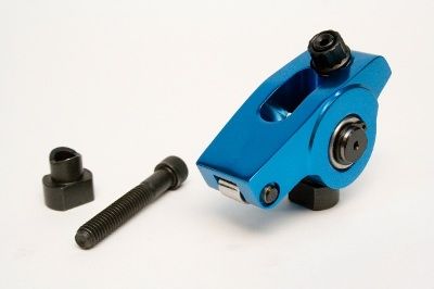
Most enthusiasts want to equip their engines with rollerized rocker arms however, therefore pedestal mount adjustable rocker arms manufactured by Scorpion (p.n.3224) or RM Competition would be my recommendation. The RM Competition rocker arm is a modified Harland Sharp rocker arm. There are several advantages to pedestal mount rocker arms:
• They require no machining of the cylinder head, they mount solidly to the factory cylinder head's slotted pedestal, utilizing a steel saddle and 5/16 cap screw.
• They provide adjustment of lash or hydraulic tappet compression via a push rod cup style adjuster, the same as a shaft mount rocker arm.
• They allow rocker arm geometry to be set with the cylinder head on the bench.
• Rocker arm geometry is not dependent upon push rod length; thus making it very easy to establish push rod length.
• Lash or hydraulic tappet compression does not impact rocker arm geometry.
• They promote better valve train stability than push rod guided rocker arms.
There are also two drawbacks to the pedestal mount rocker arms:
• They are fastened to the pedestal with a 5/16" cap screw. A 5/16 fastener is not what you want for racing, high valve spring force, or high rpm; but it is adequate for any street application as long as the fastener is of very high quality to alleviate the possibility of bolt stretch.
• They are only available made from billet aluminum. ALL aluminum rocker arms shall eventually fail. I recommend replacing the billet variety every 10,000 miles.
If the cylinder heads have already been machined for 7/16 studs and guide plates the Yella Terra YT6321 rocker arm is designed to bolt down solidly to the machined pedestals and thus perform as a pedestal mount rocker arm. This rocker arm's 7/16 mounting bolt makes it the choice for racing, high spring forces and high rpm. Yella Terra sells saddles of varying height to aid in setting the rocker arm's geometry. This rocker arm is double the price of those I've mentioned previously.
It is my hope that someday soon a manufacturer shall offer a steel bodied pedestal mount rocker arm. That would be the holy grail. At this date (2016) if a person wants a pedestal mount style rocker arm made from steel they have two choices; they can have a set custom made, or they can purchase NASCAR quality "individual shaft mount" rocker arm assemblies p.n.7200 from T&D Machine with their optional steel rocker arm. These rocker arm assemblies require pedestals that have been machined for 7/16 studs and guide plates; they are about triple the price of the Scorpion and RM Competition rocker arms.
(7) Push Rods
3/8 diameter pushrods manufactured from 0.080 wall seamless chromoly tubing are the final components needed to round-out this high performance valve train. Smith Brothers in Redmond Oregon is a great place to purchase custom push-rods. Other sources for push rods include Manton Pushrods in Lake Elsinore California, Manley Performance Products, and Trend Performance.
The amount of oil flowing to the valve train must be limited. I highly recommend using tappet bore bushings, the kit available from Wydendorf Machine is affordable, and the bushings are easy for the do-it-yourselfer to install. However if tappet bore bushings are not installed, oil flowing to the valve train can be limited via the pushrods in hydraulic tappet applications. Having an 0.040 restriction installed in one end of the recommended 3/8 x 0.080 push rods is one method for doing this; 5/16 push rods made from 0.116 to 0.120 wall thickness tubing, which have an approximately 0.072 passage in the middle, is another.
(8) Rocker Arm Geometry
Rudimentary rocker arm adjustment is aimed at keeping the operation of the rocker arm within four parameters; (1) the rocker arm should not contact the valve spring retainer when the valve is fully closed, (2) the rocker arm should not contact the push rod when the valve is fully open, (3) the rocker arm slot should never "bottom-out" against the fulcrum, saddle or stud at either extremity of its motion, and (4) the rocker arm tip should never bear down upon an edge of the valve tip; its sweep pattern does not have to be perfectly centered on the valve tip but it should contact the valve tip in the middle half of the valve tip's surface. You don’t want to “settle” for this however.
Geometrically ideal rocker arm geometry will set the rotational axis of the rocker arm at the same height (perpendicular) as the valve tip when the valve is 50% open. Correct geometry at the rocker tip will place the sweep of the rocker tip nearest the rocker arm at fully closed and fully open, the sweep will be furthest from the rocker arm at 50% open, and the rocker tip shall be in the middle of its sweep at approximately 25% and 75% open. This geometry will always result in the narrowest sweep pattern, although there is nothing beneficial about a narrow sweep pattern, it is just a method of evaluating the rocker arm geometry. This description of sweep pattern will be in direct opposition to many of the rocker geometry instructions you shall run across.

Ignition
The Ford Duraspark ignition is reliable, it performs well, and parts remain readily available. The Duraspark I ignition was Ford's first high output ignition, featuring dynamic dwell which charges the coil perfectly over a wide range of engine speed. Thus it is the preferred ignition (the original application was California only - 1977/1979), but the only aftermarket wiring harness available is for Duraspark II. The Duraspark I coil and the Duraspark II wiring harness require modifications to use these parts for a Duraspark I application, therefore this choice is only recommended for folks willing to perform the modifications (which aren't that difficult). The Duraspark II ignition is a simpler plug & play installation.
Duraspark I (red wire grommet) SMP LX210 ignition module and SMP FD477 coil; 0.060 plug gaps.
Duraspark II (blue wire grommet) SMP LX203 ignition module and SMP FD476 coil; 0.050 plug gaps.
Duraspark ignition wires SMP 69404
A Duraspark II wiring harness is available from Painless Wiring (p.n.30812), or American Auto Wire (p.n.500918); be sure to use the appropriate coil with the ignition module you have selected. The Duraspark I ignition does not utilize a ballast resistance.
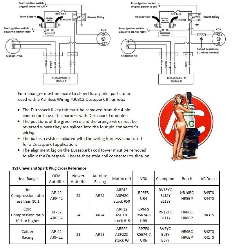
Set the ignition timing to the following spec: 16° to 18° initial advance; 20° centrifugal advance fully in between 2800 to 3200 rpm; this equates to between 36° and 38° total advance. Street engines (operated at partial throttle) should have 10° vacuum advance connected to ported vacuum. In spite of what you may have read elsewhere, a combustion chamber of fixed design (factory Cleveland), utilized with a piston dome of fixed design (flat top), with an identical dynamic compression ratio (8.0 or less), and with a fuel of fixed octane (91 US/Canada), shall require the same ignition calibration.
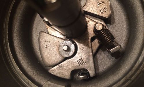
If a Ford Duraspark distributor is utilized a distributor “sleeve and plate assembly” marked 10L or 10R and replacement centrifugal advance springs shall be required to properly calibrate the centrifugal advance curve. A sleeve and plate assembly with a wider “notch” can be modified to reduce the width of the notch; the proper notch width for achieving 20° centrifugal advance is 0.410”. Ignition Engineering of Anaheim California can rebuild and re-curve a Duraspark distributor for you (telephone 714-334-9143). The MSD 8477 distributor is a good substitute for the factory distributor, and the MSD magnetic pick-up is Duraspark I or Duraspark II compatible.
Induction
(1) Dual Plane Manifold - US 4V Heads
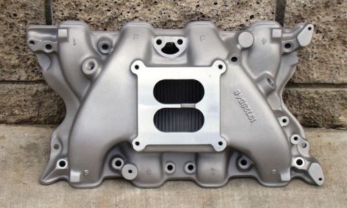
• Blue Thunder dual plane intake manifold, Pantera version (the Pantera version has a flat carburetor mounting pad).
• 4150 Holley style carburetor, 750 cfm, annular boosters, electric choke, street calibration.
• The exhaust heat passage should be welded closed unless the car shall be driven in very cold climates.
• This manifold shall give your 351C a more dramatic mid-rpm acceleration and extend its high rpm performance. All this without impacting the engine's low rpm manners. It performs better at low rpm than its large runners would lead you to believe. It has been the most popular intake manifold among 351C enthusiasts since the 1970s. Even today each production run of the manifold sells out almost immediately. How many hot rod parts can make such a claim?!
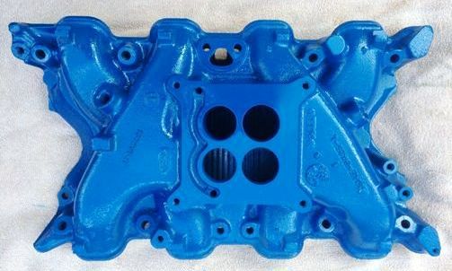
If you're a person preferring to use factory parts as much as possible, or to keep the external appearance of the engine stock, the 1970/1971 factory cast iron intake manifold, casting number D0AE-9425-L, shall be your intake manifold of choice. The manifold's carburetor flange is designed for "square bore" Holley 4150 style carburetors. The flange has 4 holes sized for a 630 cfm Autolite carburetor, the holes will need to be opened-up to 1-3/4" diameter. The exhaust heat passage should be welded closed as advised for the Blue Thunder manifold, unless the engine shall be operated in very cold climates. This manifold will not perform as well as the Blue Thunder manifold, but that is the compromise you must accept to use a factory iron manifold.
(2) Single Plane Manifold - US 4V Heads
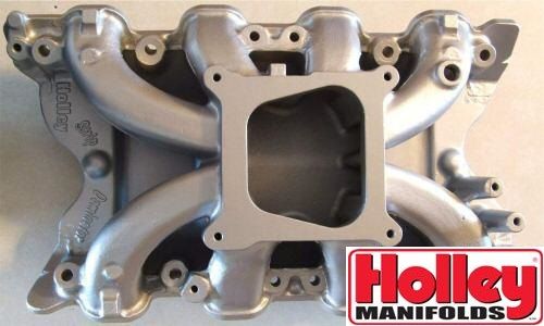
• Holley Strip Dominator intake manifold.
• 4150 Holley style carburetor, 650 cfm, annular boosters, electric choke, street calibration.
• The Holley Strip Dominator does not perform as well at low rpm as the Blue Thunder manifold, but it performs better at high rpm ... and it LOOKS absolutely bitchen. It is only available used (eBay), and since it is in high demand amongst 351C enthusiasts it sells for quite a bit of money.
• The carb mounting pad should be milled flat for appearance and/or clearance in the Pantera.
(3) Fuel Injection
• Throttle Body Injection
• Port Injection based upon a “long runner” manifold such as the Trick Flow manifold.
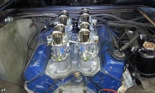
(4) Individual Runner Weber Carburetion
• Aussie Speed Intake Manifold.
• The intake manifold is available in the US from Small Town Speed of McKinney, Texas. Contact Cory at (972) 989-4003.
• Weber 48 IDF carburetors (4 each).
Four Barrel Carburetors
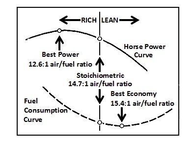
Annular booster venturis atomize fuel better, leading to better fuel distribution within an intake manifold, more consistent air/fuel ratio from cylinder to cylinder, the ability to operate at higher compression, and the ability to make more horsepower. Select a carburetor having annular booster venturis, having vacuum secondaries, having an electric choke, and calibrated for "street performance".
In terms of size, some owners opt for a 600 to 650 cfm carburetor. Carburetors of that size will fit on an unmodified 1970/1971 iron intake manifold (D0AE-L casting number). The 351C 4V engine of 1970/1971 was equipped with a 630 cfm Autolite carburetor (model 4300A). The “smaller” carburetor is probably the best choice for a street engine equipped with a single plane intake manifold as well. Check out these 600/650 cfm carburetors:
600 cfm, vacuum secondary, modest budget: Summit Racing #M08600VS
650 cfm, vacuum secondary: Demon Carburetors #1282020VE
650 cfm, mechanical secondary: Quick Fuel Technologies #SS-650-AN
However, in terms of selecting a carburetor for a dual plane manifold with a full height plenum divider a smaller carburetor offers no better low rpm performance than a properly calibrated carburetor of larger capacity. If the engine is equipped with a dual plane manifold (full height plenum divider) its performance at higher rpm will be impacted by a 600/650 cfm carburetor. Therefore if you want the Cleveland to perform as it is capable of performing, over a wide power band encompassing idle to 6500 rpm (or 7000 rpm), then opt for a 750 cfm version. The 351 Cobra Jet engine (Q code) was equipped with a 750 cfm Motorcraft carburetor (model 4300D).
A 750cfm carburetor has 1-11/16" throttle blades and 1-3/8" venturi throats. Carburetor jetting should be approximately #68 to #70 primary jets, and approximately #80 secondary jets. There are very few choices if you limit the selection to those having annular booster venturis, an "electric choke mechanism", and "vacuum secondaries". Check out these vacuum secondary 750 cfm carburetors:
750 cfm, modest budget: Summit Racing #M08750VS
750 cfm: Demon Carburetors #1402020VE
If your preference is a mechanical secondary (aka double pumper) carburetor, check out these 750 cfm versions:
Quick Fuel Technologies #SS-750-AN
Holley #9379
Demon Carburetors #1402020
The Holley and Demon mechanical secondary carburetors do not come with electric chokes, but an electric choke can be added to either of them.
Are you looking for a good mechanical fuel pump to supply your carburetor? The Robb Mc Performance #1020 mechanical fuel pump is rated for up to 550 horsepower. Its very reminiscent of the old Carter NASCAR pump. Its a tight fit with the oil filter, you may want to do a little "relieving" with a file to make some clearance before you bolt it up permanently.
Plumb the fuel system in metal tubing as much as possible, keep the hose sections as short as possible, use a tubing bender to put smooth large radius bends in the metal tubing, do not use 90° tubing fittings. Plumb the pump suction in ½" (AN-8) tubing or hose and plumb the pump discharge in 3/8" (AN-6) or ½” (AN-8) tubing or hose. Install a high flow fuel "pre-filter" designed for the fuel pump inlet (75 to 150 micron) and install a high flow fuel "post-filter" designed for the fuel pump outlet (10 microns for fuel injection or 40 microns for a carburetor).
Pantera Exhaust
Pat Mical headers, PIM headers, or Hall GTS headers; any of the 3 connected to Hall GTS tail pipes. The diameter of the header primaries should be 110% the size of the exhaust valves, 1.65 exhaust valves need 1-7/8" OD primaries; 1.71 exhaust valves need 2" OD primaries.
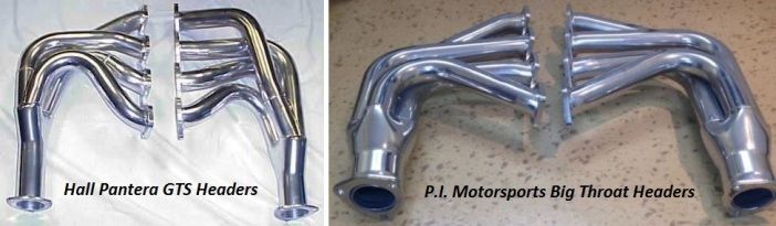
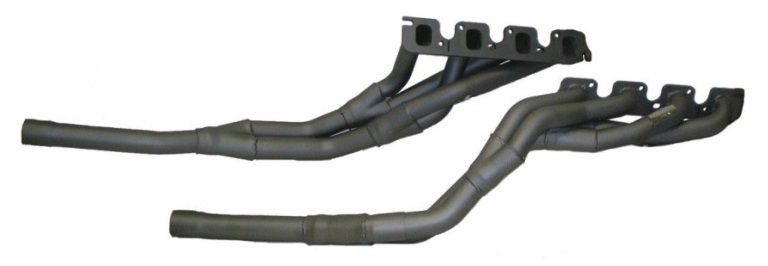
Tri-Y headers, if available for your application, best complement dual plane or individual runner induction, and are best suited for street and road racing applications. The headers pictured below are manufactured in Australia for Australian Falcon applications.
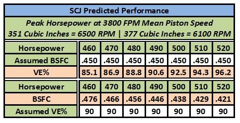
For those who want to build a high horsepower street engine may I suggest starting with the 377 CJR long block as a foundation. Increase the static compression ratio as far as you feel safe to do so. I would recommend 8:1 dynamic compression, which is equivalent to 9.63:1 static compression. Perform the valve pocket and exhaust port work explained above. Utilize roller camshaft number 4. For induction choose the Holley Strip Dominator intake manifold and a 850 cfm annular booster carburetor (Holley 9380 or QFT SS-850-AN). Tune the carburetor well. This induction system will yield about 90% volumetric efficiency at peak horsepower.
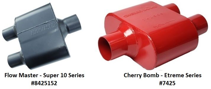
To achieve the best horsepower the Pantera exhaust system will also require mufflers providing lower back pressure than the ANSA mufflers; Pantera owners may want to check-out the Flow Master #8425152 Super 10 Series muffler and the Cherry Bomb #7425 Extreme Series muffler.
(1) The dynamic compression ratio is miscalculated, set too high for the fuel octane the owner planned to use.
(2) The No.1 cam bearing is installed too deep into the block.
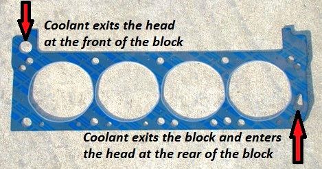
(3) Improper head gasket orientation.
(4) Bearing clearances are too tight (i.e. set to factory spec).
(5) When replacing the rear crankshaft rope seal with a neoprene seal, the pin in the seal groove of the No.5 main bearing cap is not removed
(6) The wrong thermostat is installed
(7) The brass orifice below the thermostat is missing

(8) The OEM oil pump drive shaft (intermediate shaft) has been replaced with a “heavy duty” shaft.
(9) The distributor drive gear is too loose on the distributor shaft.
(10) The owner has been “talked into” using a brass distributor drive gear
(11) The water pump “recirculation passage” is not drilled-out in some aftermarket water pumps.
(12) Ford 5.0 HO hydraulic roller tappets have been utilized.
(13) Improper hydraulic tappet adjustment (compression); normally excessive (1/4 to 3/8 turn is good).
(14) Valve stem to valve guide clearance too tight.
(15) Materials chosen for valve seat inserts are incompatible with stainless valves (needs iron or beryllium copper).
(16) Camshaft “lobe centerline separation angle” (i.e. LSA) is too tight, creating 3 problems
• Excessive overlap for a large canted valve engine thus degrading low rpm power and drivability
• The exhaust valve opens too late thus causing power to fall-off prematurely at high rpm
• The intake valve closes too early thus boosting dynamic compression excessively
(17) Improper break-in of flat tappet camshaft (under-lubricated)
(18) Improper oil has been selected. Read Here: 540 Rat Blog on Motor Oil
(19) Oil additives which diminish the wear properties of oil have been used (this includes ZDDP additives)
(20) Improper break-in of rings, creates oil burning (over-lubricated during assembly)
(21) Excessive connecting rod side gap, creates oil burning (should be 0.010 to 0.020)
“I cannot teach anybody anything. I can only make them think” ― Socrates
I've had a life-long interest in the Cleveland Ford, I believe these are the most intelligently conceived high performance Cleveland street engines I've penned up to this date (2016). Time will tell if anyone agrees. Thanks for reading down this far. If you have any questions, comments, or constructive criticisms please feel welcome to post a reply.
Debbie and I love you guys.
