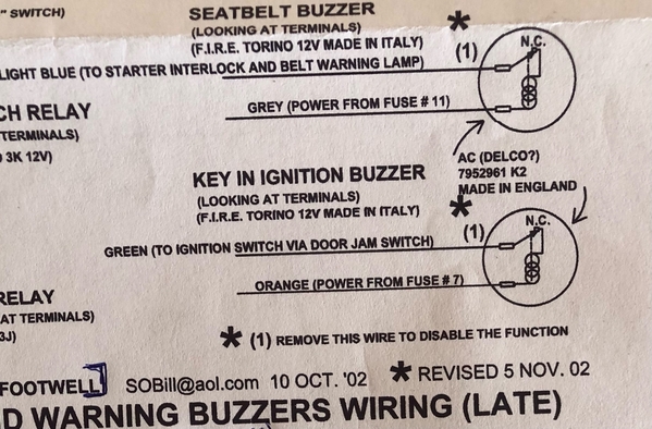
Trying to get my ignition buzzer working. It's the bottom element in the drawing below. It doesn't work right now, but I verified the "buzzer element" operates properly (buzzes if 12V is applied).
Can someone explain how the circuit is designed to work?
1) Does it only come on when the door is opened, and the key is on?
2) Does it shut off if the engine is running and the door is open?
- I was under the impression that it buzzed when the ignition was turned on, and the engine was NOT running to prevent you from burning up a coil or ignition module. IF THIS THEORY IS CORRECT... How does the circuit work?
Help is appreciated - I'm going to look at the schematic, but maybe first I should read the owner's manual.
Thanks -
Rocky
I made this table of data with the two Buzzer systems. My seat buzzer doesn't work because I have swapped out the stock seats for C4 corvette seats, but I'm hoping the ignition buzzer might operate without too much work. Wiring seems very stock under the driver's kick panel. The data doesn't make sense to me.
(Green & Orange are supposed to be ones to the ignition buzzer)
Wire Color Batt ON IGN ON Engine ON OHMS
to GND to GND to GND to GND
Lt. Blue 0 V 0 V 0V Infinity
Grey 0 V 11.8 V 12.0 V 9 Ohms
Green 0 V 0 V 0 V Infinity
Orange 12.5 V 11.9 V 13.0 V Infinity


