

Here's my 2 cents of what is wrong with the cooling system:
- The OEM cooling system collects air in the radiator.
- The OEM cooling system flows too little coolant (most problematic at low rpm).
- The OEM cooling system controls the fans poorly.
Based upon those observations there are a few "basic improvements" to make.
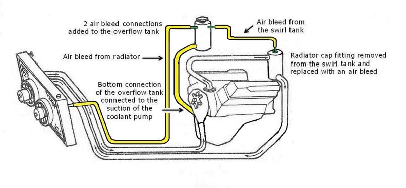
Air management:
Have you ever wondered why the Pantera's coolant recovery tank is over a foot tall and has a pressure cap on it? Its obvious to me by their designs the "system tank" and the "recovery tank" were originally intended to be a "swirl tank" and a "head tank", respectively. Obviously someone realized the need for a "race car style" head tank during the Pantera's design phase. I have found documentation verifying the tanks were indeed altered, but I haven't yet found any documentation explaining "why" the alterations were made.
Alteration of the two coolant system tanks was among the very first modifications made to the Pantera when Ford stepped-in, yet none of the 2 or 3 air removal schemes instituted by Ford were successful at removing air from the radiator. I assume once Ford's engineers altered the tanks budgetary concerns (or ego) prevented them from going back to the original design.
The cooling system needs a low pressure place in which to collect air and isolate it from the cooling system ... i.e. it needs a "head tank". The logic of this is obvious and inescapable when the lay-out of the cooling system is viewed from the side, or when the pressure zones within the cooling system are considered. All modern cars have head tanks for trapping air, but back in 1970 this was race car stuff, it would have been an advanced design for a production car in that era. Fortunately it requires only four small revisions to enable the two tanks to perform their originally intended purposes. By doing so air can be bled from the radiator into the lower pressure of the head tank and thus it can be automatically and continuously isolated in the head tank where it does no harm. The head tank also provides an air space for the expansion and contraction of the coolant in lieu of a recovery tank.
Maintaining coolant back-pressure within the engine block aids in preventing air from being released within the engine block. So the OEM location of the thermostat, at the engine's outlet, is the ideal location. Air shall be released downstream of the pressure drop created by the thermostat. With the "system tank" revised to function as a "swirl tank" (aka a de-gas tank) and located immediately downstream of the thermostat as it is, it shall collect the air and channel it to the head tank before the air has a chance to circulate within the cooling system, as all swirl tanks are intended to do.
Everyone who has performed these revisions speaks quite positively about the results.
In lieu of the head tank, a simple drain petcock can be installed in the top of one of the radiator tanks to facilitate manual bleeding of air. Each owner should utilize one scheme or the other.
Coolant flow:
Coolant pumps are centrifugal pumps; such pumps do not have a linear output (i.e. flow) verses speed curve. The pump must rotate at a certain minimum speed in order to reach the point in which increases in speed result in increases in output. Below that speed the pump's output does not increase with increases in speed. The speed at which the pump's output begins increasing varies based upon the resistance to flow (i.e. head) at the pump's outlet. As the resistance to flow increases it requires a higher pump speed in order for the pump to enter that part of it's output verses speed curve in which increases in speed result in increases in flow. The Pump's maximum flow capacity shall also decrease as head increases.
Neither the OEM Ford coolant pump, nor ANY of its replacements, were designed to pump coolant over the distances it must be pumped in the Pantera's mid-engine application. The amount of head in the Pantera's cooling system caused the OEM coolant pump to drop lower in its output verses speed curve. The pump simply doesn't pump enough coolant at idle speed. Considering the nature of centrifugal pumps it should be no surprise that the lay-out of the Pantera's cooling system impinges upon the coolant pump's output, I am surprised this was not predicted by at least one of the engineers involved in the Pantera project.
Coolant pump output can be improved by 3 things:
- A pump with a different output verses speed curve.
- Higher rotating speeds for the OEM pump.
- Less resistance to flow (aka less head).
The average owner can improve flow most easily with a couple of "bolt-on" parts; the SACC 10% overdrive pulley driving the Flow Kooler pump.
PUMP and PULLEY: The idea for the overdrive pulley came from the De Tomaso factory. In an interview Odoardo Govoni revealed that the factory provided him with an overdrive pulley for his Group 4 race car (the most winning Pantera race car ever) circa 1974. The interview is found on page 102 of Philippe Olczyk's book. Owners who have installed the SACC pulley have reported an immediate drop in coolant temperature with no other changes.
The Flow Kooler pump has a machined billet impeller which they claim improves low rpm flow. Pantera owners speak highly of this pump as well.
PORTED VACUUM SWITCH: The Pantera's ignition controls were augmented by DeTomaso with an electric ported vacuum switch (aka the PVS valve) to contend with the overheating issues. The vacuum switch was designed to retard the ignition thereby reducing the engine’s idle speed by 100 to 400 rpm when a predetermined high temperature limit was reached. Retarding the ignition increases the cooling system's heat load, while reducing idle speed also reduces the speed of the coolant pump, thus reducing coolant flow. This response to high coolant temperature was opposite to the way in which Ford’s ignition controls were normally designed to react to high coolant temperature. The electric ported vacuum switch did not alleviate the Pantera's propensity to operate hot during stop and go driving ... it made things worse.
The PVS switch should be disabled and removed from every Pantera in which it was installed. The distributor's vacuum advance connection should be connected directly to the carburetor's "ported vacuum" connection, and the distributor's vacuum retard connection (if so equipped) should be left open to atmosphere.
THERMOSTAT: The thermostat built into the 351C was an advanced design for its day. Ford engineers referred to it as a "controlled bypass" system. It increased the amount of coolant bypassing the radiator during warm-up in order to eliminate hot spots in the cylinder heads during warm-up and to provide faster warm-ups too. Once the engine reached operating temperature the coolant bypassing the radiator was shut-off completely. Similar functionality is accomplished in modern cooling systems with divorced thermostats, but the Ford engineers who designed the 351C accomplished it with an internal thermostat. The OEM "Robertshaw 333" style thermostat was a high flow thermostat as well. I don't believe you can improve upon the OEM thermostat design built into the 351C if the proper parts are utilized.
RADIATOR: When the time comes to replace the radiator, the replacement should be chosen based on core design. Radiators with less restrictive cores (promoting an increase in the coolant flow rate) should be chosen. I like the copper radiator sold by Hall Pantera, it is equipped with a beefy "truck-style" core known to alleviate cooling system problems.
RADIATOR OUTLET PLUMBING: The suction of the 351C coolant pump has a 1-3/4" OD hose connection. The radiator outlet of all Ford's V8 equipped vehicles was also 1-3/4" OD. In the Pantera the plumbing between the radiator outlet and the coolant pump inlet is 1-3/8" OD, which is much too small and constitutes the most severe "resistance to flow" in the cooling system's plumbing. Rubber hoses located on the radiator's outlet plumbing tend to collapse at idle due to the severity of the resistance to flow.
The coolant pump inlet was originally connected to the radiator outlet plumbing via a 90° metal tubing elbow and a 90° rubber hose elbow. The rubber elbow was known to collapse at low engine speeds which severely restricted coolant flow. This plumbing arrangement was replaced in May 1972 by a "double-bend" metal tube which only used a short-straight rubber hose to connect to the pump inlet. According to Ford the new arrangement was made to create more clearance for the shift linkage. Whether it was intentional or accidental the change also improved the cooling system, by reducing or eliminating the collapse of the rubber hose on the pump's suction.
Therefore steps must be taken to prevent the collapse of any rubber hoses on the radiator outlet plumbing. There are three ways to do this including (1) keeping all rubber hoses as short as possible, (2) using stiff-thick wall hose such as "Gates green stripe" hose, or (3) installing something within the hose to prevents it's collapse (such as a piece of 1-3/8" OD stainless steel tubing or the coiled wire from a radiator hose designed for another car).
If you are considering making revisions to the coolant system plumbing then increasing the size of the radiator outlet plumbing to 1-3/4" OD is where to begin your effort. That's equivalent to a 62% increase in cross-sectional area ... no small matter. Given the cooling system problems the Pantera was having I'm sure Ford engineers identified this problem. I assume budgetary or managerial constraints limited how many changes they were allowed to make, and reconfiguration of the radiator baffle was given priority.
Fan control:
Speaking of the radiator baffle, the Pantera's radiator was originally equipped with a vertical baffle. The vertical baffle did not seal well inside the radiator's tank however and it allowed too much coolant to bypass the radiator. Ford reconfigured the baffle in April 1973, replacing the vertical baffle with a horizontal baffle. The Ford engineers were quite right in prioritizing the elimination of this issue, it had been the worst of them. Once the horizontal baffle replaced the vertical baffle a Pantera could idle all day long without over heating, on a hot summer day, with the air conditioning operating.
Reconfiguring the radiator baffle had a detrimental impact upon fan control however! The fan control switches, which had both been originally installed in the radiator's "outlet" tank, ended up being located in two different tanks due to the reconfiguration of the baffle. But Ford did not revise the temp settings of the fan control switches. The fans haven't cycled properly since.
The reason the Pantera is equipped with two cooling fans is due to the rectangular shape of the radiator. If the radiator was "square" it would only have one fan and if there was only one fan nobody would feel the need to control it with more than one temperature switch. Just because there are two fans does not mean they have to be controlled at two different temperatures, there is nothing gained by doing so. Its puzzling why De Tomaso or Ford engineers chose the complication and the expense of two switches over one.
Designing an automatic fan control should have been simple, its something which other cars of that era did quite successfully with one fan switch. Owners of other cars equipped with electric fans took fan operation for granted, Pantera owners should have been able to do the same. Consider the two fans as a "fan system" and control that fan system with a single fan switch. The switch should be mounted in the radiator's inlet tank, set at a temperature which complements the setting of the thermostat. The fans will cycle on and off automatically as needed if a switch set to control at the proper temperature is chosen. If the fans run all the time then the cooling system is running too hot, or the wrong switch was chosen.
Switch Manufacturer...Part Number.........Switch Setting in °C........Thermostat
Intermotor.................50104..................97°/92° ........................192°F or 195°F
Intermotor.................50200..................92°/87° ........................180°F
Wahler......................823.959.481.F ......92°/87° ........................180°F
Notice there is no mention of high flow fans. This is not an oversight, its intentional. High flow fans are a Band-Aid fix, they may help a marginal cooling system but they don't address the core problem. Coolant flow is the real issue, not air flow. Of course, folks who operate their Panteras in truly hot climates (like Arizona) can make good use of those high-flow fans.