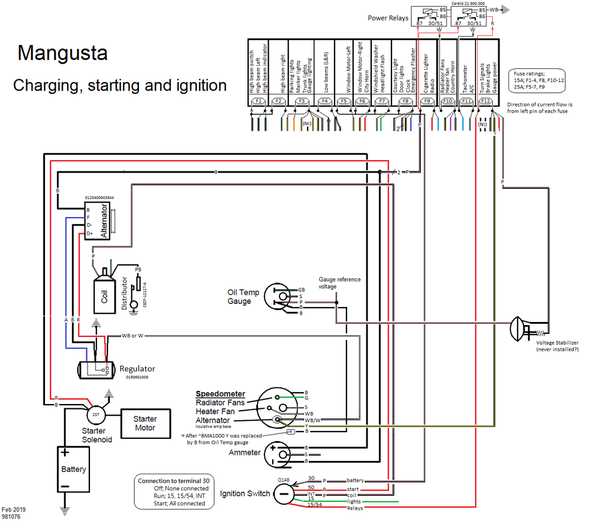
Attached is a functional excerpt, basically everything needed for starting the car and charging the battery...Maybe the most interesting thing here is the Alternator light, some detail that wasn't on the Hall diagram but also changed around 8ma1000. We left the "voltage stabilizer" in the diagram even though we have no evidence it was ever installed, however it seems that earlier Goose had an independent wire (yellow) from F12 to the alternator bulb. This would have been required if the Voltage Stabilizer was installed (since the voltage stabilizer drops the voltage to 8-10v, the Yellow wire was needed to provide a real battery reference for the bulb so that it would not always be ON...). But somewhere before 8ma1000 the wiring harness changed to create a stub wire from the adjacent Oil Temp gauge, and at some time (probably early 8ma10xx) the Pink wire (also from F12) was used for the alternator light and at least by 8ma1046, the yellow wire was not installed in the wiring harness.
Note that an LED bulb can NOT be used in the alternator light, an LED is a diode and a bulb is needed to conduct current in both directions. Pantera included a 15ohm resistor (13005A) across the bulb, so that even if the bulb burns out there is an electrical reference back to the regulator. Also to emphasize, the lamp socket used here is different than used for all the other gauges (which ground one connection of the lamp to chassis thru the gauge can...). For Pantera, this is 13006B "dual terminal," the physical style was different on Mangusta but either should work.


