

OK, new bits of steel (shown on right) are cut, bored to 10mm i.d. and fitted to left and right shock supports. (That is what the flat spot is...to allow it to fit down closer to the support. Welding takes care of strength issue here as force of motion would be upwards, away from the thin flat area.)
While I had the lathe set up, I also modified my upper shock bushing adapters to a 10mm ID. Previously they were 3/8"....because I cheated and installed US bolts that I had lying around....! Now every shock mounting hole goes back to stock 10mm sized stuff....and nylocks!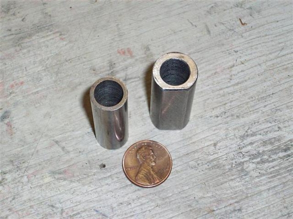
Welded up LH support...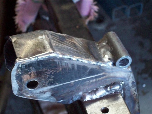
Welded up RH support...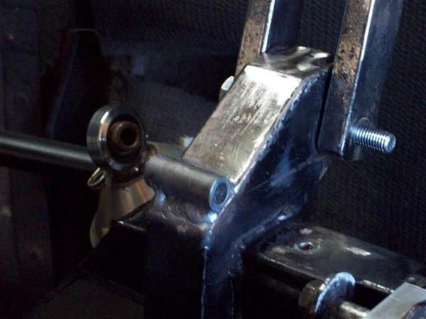
All done!!! Well, almost....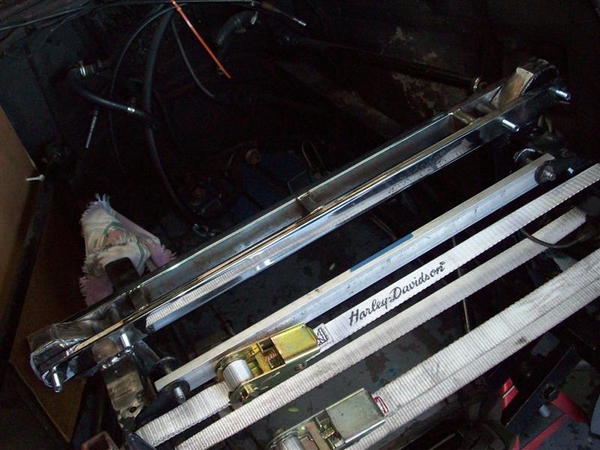
I had to use the straps to pull the frame rails in ever so little to get all the thru bolts to slip in. At this point, all 4 bolts slide in and out loosely! That will never happen again! Seriously.... I fitted the ladder bar with body weight working against the suspension (upper rear a-arm) sitting on the ground. Once the engine etc is mounted, I may actually need to spread things apart, OR, use a combo of the jack and jackstands in different locations to get bolts to "slip easily" back in place. At least two bolts at any one time should be a slip fit!!!! Minor details....
So what now??? I want to clean up some of the welding areas to get splatter and some high spots lowered a hair, where I dwelled a bit to long with the MIG tip....
I want to make up some quick "shock dummys" to use while I refinish the rest of the engine bay....so that the shocks are not in the way of sanding dust and other such sorts of crap....while I am stripping off old frame/chassis/firewall paint in preparation for new paint and heat insulation/padding! I think I have some 1" square tubing scrap around here somewhere.....
Ciao!
Steve
Attachments
Images (4)


