

Well, here we are mid week, wondering if I went forwards or backwards!!!?
Some updates:
Distributor gears: orange is for a flat tappet cammed 302...ugh. Just what I don't need! Not what I was sold either....this "had been in a roller cam motor..." Yah, may have been in it, but wasn't correct!
It is in great shape, very little use on it, so will go in the spare pile for spare 302 parts...non-5.0L parts!
Yellow paint: AHAH...for a 302...and a 351W....hmmm. This won't fit either....in the early 90's or late 80's.... Ford decided to use the same gear for both engines...seems logical! That made the shaft diameter grow to about .530" from .470 or so.... Another part for the "spares" pile!!! But it will work for the old 351W if I ever get around to that project.....ugh.
Ordered a new gear off of ebay...we'll see what happens.
Tore down the distributor and am working on learning about advance curves etc.
All it really did is make me wonder about "what is the more ideal magic approximation" of a max timing figure? I had always thought 34-36 degrees but that may just be for the Clevelands.....and we're talking 302 here.... What was odd, is that the mechanical advance mechanism under the "breaker plate" had the stop set up in the "21L" slot, allowing it to advance a whopping 42 degrees! (2x the stamped number= advance degrees.) Add in 4 degrees of static or initial timing and you've got a whole lot of timing! I guess the old 80's non-roller, non-efi engines were pigs with low compression.....
Again, will need to do a little more research on timing max value and a curve. I understand that both are a matter of how much compression you have......and of course...fuel quality....
Pulled the old gear off of the distributor tonight and put all the bits away for later reconstruction!
Carb Gasket/spacer: Found an Edelbrock #9266 extra thick gasket (.320") with four longer carb studs in Summit's stuff on ebay. About $20 shipped... Would cost me at least $5 in driving around.....I'll let the UPS or FedEx guy deliver...will give the dog something to get excited about.....
Hoses: Trying to figure out what I bought for a lower water pump hose....I thought I may have borrowed it from my stock of 68 Cougar parts....we'll see!
Worked more on the fitment of the jackshaft bracket to the intake. I want to have a rear support boss welded onto the intake....so cut up a mock piece out of some firewood.... then found a piece of aluminum....but need to shave it down with a mill to .352" thick and then had file it to fit the contour of the intake runner.... It shouldn't take much stress...just act as a support for the jackshaft bracket to keep it from rocking.
Looked at jackshaft bearings and how to get them on and off..... THIS is going to be a real PITA!
I have a puller for getting bearings off..but this really only works well for the end bearings. (I will need to get more threaded rod....for doing the middle bearing!) I believe this is an OTC (Owatonna Tool Co) puller that I got either off of ebay or from Harbor Freight....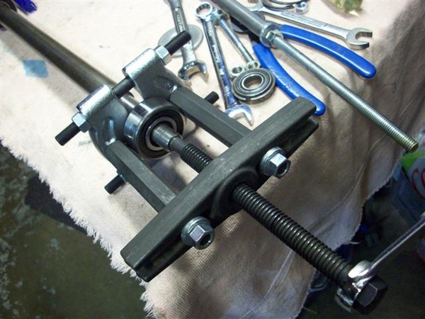
I had put the new bearings on the shaft earlier.....in anticipation that this would be fairly straightforward and easy! HAH! What was I smoking????
Stopped by Home Depot on the way home from work and snagged a 3ft piece of 3/8" threaded rod, a 5" length of 1" black pipe (only because they didn't have an 18" piece of it!...), and one more can of silver paint to do the trans crossmember in.... (Threaded rod to pull bearings thru bores to make it "not like the first time" when doing final assembly, and the 1" black pipe is for "tapping" the rear bearing on if need be...
Since my jackshaft bracket was new, I did some deburring of the inner bores and around where the snap ring grooves were cut. I then used the threaded rod and any number of round things with a minimum of a 3/8" hole thru them to act as pushing or pulling bits to help move a bearing through a hole! I even put an old throw out bearing to good use!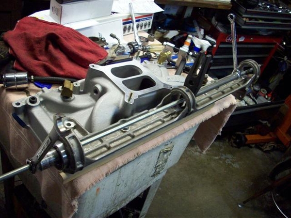
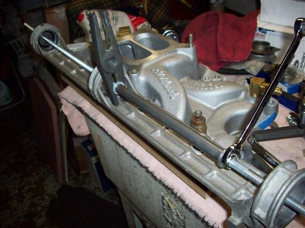
I put a small amount of anti-seize in the bores and slowly applied pressure to the nuts on the threaded rod. Starting with the center bore hole I got about 70% thru and it stopped. Since the bracket was not bolted down to anything, I saw that the front section of the bracket was starting to bend under the pressure.
I would need to fabricate long spacers to put in between the bearing bosses at the top, to prevent the bracket from bending towards the un-cast side. I stopped, reversed the pile of adapting parts, and pulled the bearing out. Did a little more deburring, polished it up with some worn 320 wet/dry paper, put in more anti-seize, and this time pulled the bearing through with little opposition! Wiped off the mess I made with the anti-seize and pulled the bearing through again!
Repeated the process with the front bearing and also the rear bearing. I have a pic I'll post later of the polished finish that resulted!
Here is a pic of the rear most bearing area after pulling the new bearing through twice. Nice and polished!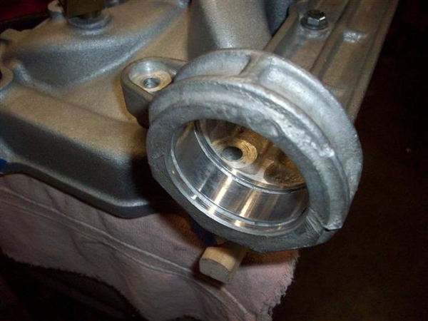
A quick check of the parts book to look for bolts (more in a bit) and found that there are three different versions of jackshaft bracket! This is a later version, that has a 52mm rear bearing where previous versions used a 47mm bearing.
As a result, I need to stop at a bearing house and pick up two snap rings for the larger bearing!
While trying to figure out the bearings, I was staring at the bracket mounting bolts(4) wondering how this shaft would best go together, and how are you going to get it all into a press......and then tighten the darned mounting bolts down again..... OR, mount it on the engine then figure out how to press the shaft into place......
With the shaft in place (OK, just barely in place!) I figured out that conventional hex head bolts are not going to be removable. Once in place they stay in place! Cannot get a good wrench on them either....not to do 18-20ft-lbs of torque on them! Socket doesn't fit on straight, and you can get in with an open end wrench...but not so good in the case of the rear most bolt......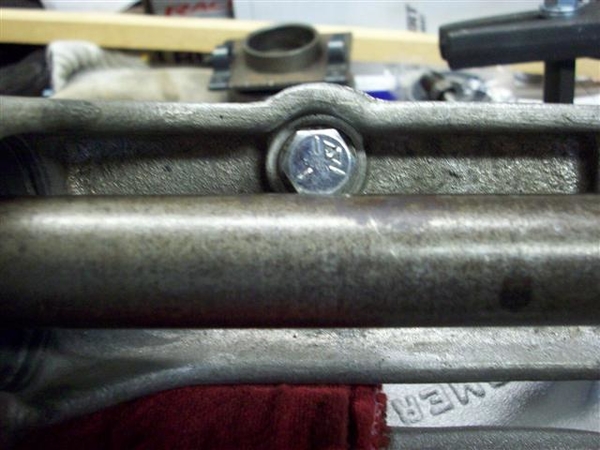
This one actually looks good compared to the next one and the rear most bolt....which looks darn near impossible....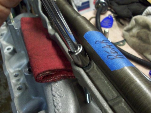
SOOOO, here is where I need your help! Providing you own a Mangusta with an operational jackshaft in place! What sort of bolts are holding your jackshaft down? Hex head? Allen head? studs with special nuts??? (the parts book did not list special bolts to use for the jackshaft mounting.... ![]()
)
I'm going to see if I can get some 3.5" Allen headed bolts to see if they will work. They take a 1/4" Allen wrench, so would just get a socket attachment that size....to throw in the tool box..... These bolts are graded higher than a grade 8 bolt, so should be up to the task of holding down an intake manifold....
Carb update: I really don't like the RH fuel entry on the carb, as I will need to bend up a perfectly good 1-->2 chrome fuel line....to clear that danged jackshaft bracket again! I tried to use my old one but it had been bent too many times before...and cracked. More for the scrap pile! But I had a new one standing by in another spare parts pile....but I really don't want to bend it up...and run fuel line across the intake manifold.......
If I change the bowls to Dominator type fuel bowls, I can change the feed side from the RH side to the LH side just by changing the fittings. I will need to install an accelerator pump diaphragm in the rear bowl, but I can take the arm off so that it will never pump fuel. (Not that the carb body is drilled anyway....) This and the finish of the bowls...natural "Holley green or brown" vs polished nickel or something.....will be different from the original... I just happened to have three new Dominator bowls hanging around...again, in that other spare parts pile....along with some new reusable gaskets (if this carb doesn't have them already), and an old but good accelerator pump rubber, and cover. I can take the pump arm off to prevent it from pumping or getting bumped and pumping....
Valve covers: figured out that the ones I wanted to use, late model "powered by ford" off of about an 83-86 EFI Mustang, will not clear the rocker lock nuts on the roller rockers. Baffle hits. Can't take the baffles out....good way to oil down the car behind you....!!!
I think I will go with a set of the new "Boss" covers that look like the old Boss 302 with the fins on the top, but they bolt up to the 289-351 type heads! Since I want to run the DeTomaso "pork chop" emblem that was stock on the valve covers, I can place them to cover all the false claims of a Boss 302...and stop the stupid questions before they roll off of a tongue! ![]()
![]()
![]()
Finding someone that can actually tell you what they are selling is a different matter.....some ads say no baffles, no grommets....others say comes with it all! Some say "stock height" (for what????) others say will clear "most" rocker arm combo's..... Of course all of the folks selling these valve covers use the "corporate" press release photo, which really doesn't show you what it looks like because of the poor angle it was taken at.......ugh.
So, you can see where I can't tell if I went forwards or backwards.....!
Ciao! Pictures later....(added 4-29 after PCNC meeting!)
Steve


