

Rich,
If you have the time to put together a simple diagram, I would surely love to compare it to a couple of jackshafts up here that are still waiting to be installed! I missed an opportunity of another club member who installed his on Sunday! He was helping me on Saturday and hadn't known I was running into dimensional issues!! Ooops!
I'll put my pulleys back onto the shaft after I pull it all apart again, and see what the pulley center to center dimension is and go from there! It can't go back together the way it is.....
OK, just like Playboy wouldn't be the magazine that it is without pictures to go with the excellent stories, here are more pictures of what I have been rambling about!
Here is some catch up from two weeks back! ( A coupe of repeat pictures here.... oops!)
Pulling bearings from the shaft. Much discussion about whether these should be a slip fit or a press fit! Pulleys and nuts hold them in place..... OTC puller set purchased off of ebay, reasonable import stuff.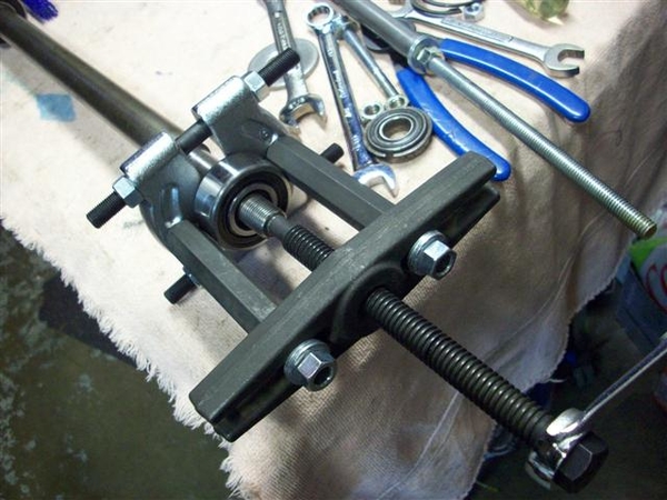
Here I'm pushing/pulling a bearing through the rear hole to burnish it a bit, and to make sure that they will go through! I pulled a bearing through each hole at least twice. Thin coat of anti-sieze was used.....that stuff gets on everything.....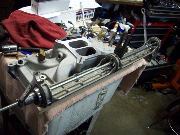
I had to be careful not to put TOO much pressure on the bearings as the jackshaft bracket would distort! So when ever possible I pulled from the center hole to the rear or the front...not the entire span front to rear.
I have not cut any short rod for doing this....but it would come in very handy!!! Long rod= lots of nut spinning! You can see a long piece of steel that I had left over from making my extra rear shock support attaching points, to take up space fast!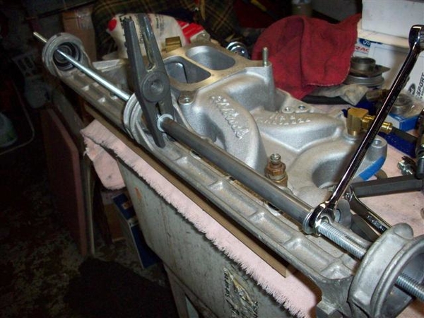
Here is a close up of the rear surface after the bearing has gone through twice. Once you get it moving, it goes just fine. Not a slip fit!!!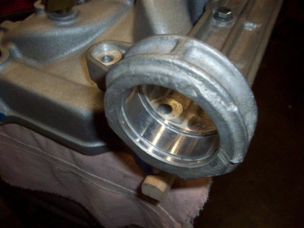
Here is a problem area for me! Hex bolts just are not optimum for the two rear bolts in my setup. The fronts aren't a great fit either! Now my shaft has been remade....so I have NO idea if the diameter is proper or not.....your mileage may vary!!!!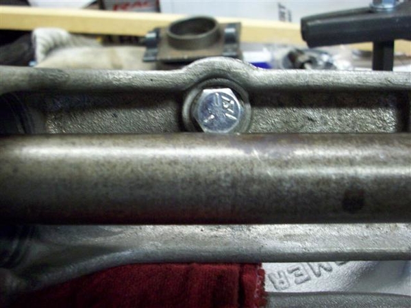
Here's what I mean! I'm switching to allen headed socket bolts. Not ideal but better. I will need to get a "long shank" 1/4" drive bit...short ones won't cut it!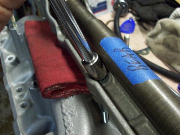
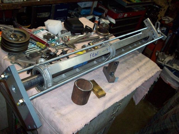
Here is my collection of misc bits and pieces that I had made up for pushing everything together. Note the pieces setting on top of the bracket, that I made from angle aluminum, to prevent the shaft bracket from bending under compression. They seemed to work....but it took a few sets of hands....tools are not finished yet.....to be one person things....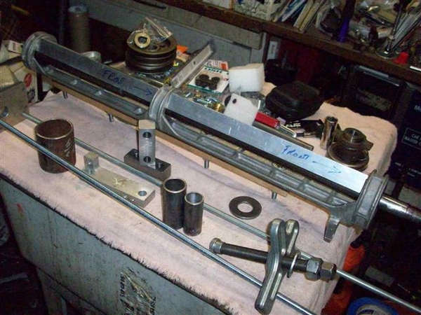
Closer view...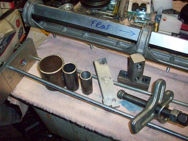
Large circular thing is for pulling rear bearing out. Circular thing in the middle is for pushing the rear bearing in, smaller circular thing is for pushing the front bearing in. Rectangular aluminum piece is for pushing on the circular things via the harmonic balancer puller. It needs a couple of holes drilled in it so that it will slip over the threaded rods when used for removing or installing... Pieces holding the jackshaft up are the drill blocks I had made up for dealing with my rocker arm stud holes. They worked great!!!
Front bearing installed. Note how it is just proud of the bracket! I think it needs to go in a tad....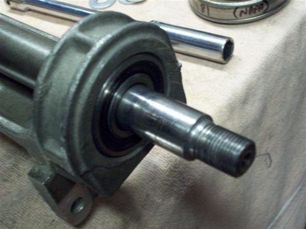
Rear bearing in place, snap rings installed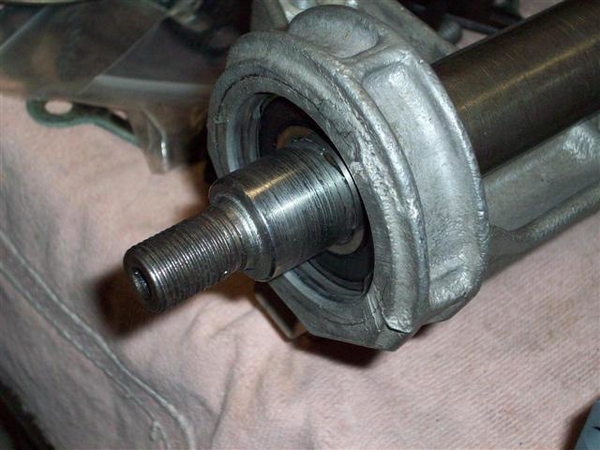
Center bearing removed...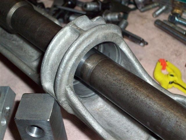
Here is are shots of the whole installer thing assembled.. It was good theory..... Would love to see what a good bearing shop uses!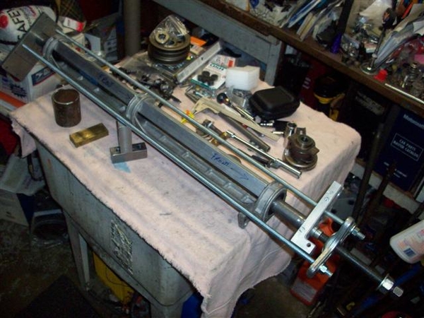
Front pulley installed. Note the amount that the shaft sticks out! Pulley is also hitting the bearing seal, so would need a small spacer which would push the pulley out more...yet it needs to go in about .125" to align with the water pump pulley! So I think push the bearing in 1/4" (cut shaft to fit...) use a 1/8" spacer behind the pulley to keep it off of the bearing seal....and should be great! Will need to revisit this dimension, as there is a recess in the back side of the pulley that will need to be accounted for.....also!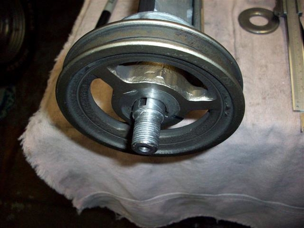
Another view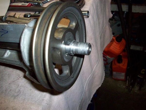
Outward facing sides of the pulleys and the various pieces I used to space and secure. Rear is on the left and front is on the right.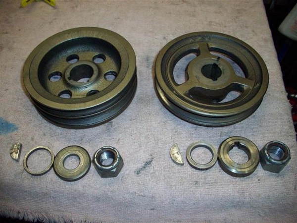
Inward facing sides of pulleys: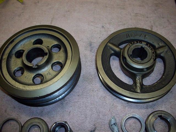
OK, next pictures are not for faint of heart!!!! Drilling on a mostly assembled long block.....!
Drill block in place, drill stop in place on drill bit. Worked nicely!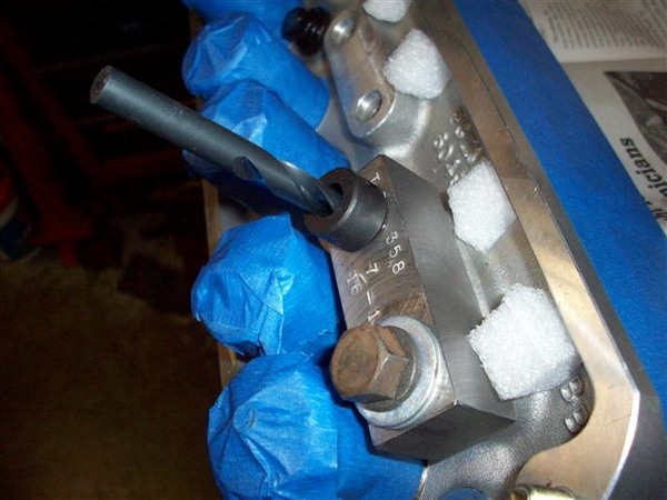
A bottoming tap, for getting more threads into a blind hole.. Note how the tip is not so pointy, as most of that point has been removed to allow the tap to go in the hole that 2 or so turns! Use solvent, WD-40, or even water when tapping aluminum to keep the tap from gumming up.....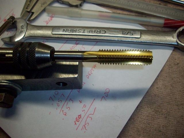
OK, enuf for me tonite! 16 holes are drilled and tapped.....on to push-rod guideplates again!
Steve
Attachments
Images (19)


