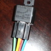
I have a fluidyne radiator with flex-a lite pusher fans and my bright mechanic hooked up both radiator temp senders directly to red and black cables coming from the car without a relay so im guessing they both fried. I hooked up these cables directly to the battery and each one (red or black) power up both fans. . I want to hook up a new temp sender to a 30amp relay and power up both fans. The 30 amp relay has various inputs.Any suggestions on how to hook it up?thanks

Attachments

Images (1)
  • temp_sensor_relay
Original Post

Replies sorted oldest to newest

Terminals 85 and 86 are the power inputs for the electro magnetic coil of the relay. When it gets power, it pulls the relay shut, closing the circuit between terminal 30 and terminal 87. At the same time, it will open the circuit between terminal 30 and 87a.

To turn on the fans, you want terminals 85 and 86 to receive 12 volts - one terminal (doesn't matter which, although they may be labeled + and -) will be the negative, the other one will be the positive that passes through the temp sender when it closes (reaches its set point). The two temp sensor wires are, therefore, a positive 12 source and the positive switch leg that is created when the set temp is reached and the current is allowed to pass through the temp sender; this switch leg positive is the positive source for the relay coil.

When this 12 volts hits 85 and 86, the relay pull in and will complete the 30 to 87 circuit.

The power for your fans is twelve volts from a source (it can be the same as for the temp sender) that you are sure has the amperage rating for the draw of the fans - and the fans should be wired to always receive a full time negative feed. The relay is a single pole and only switches one of the two wires needed to get power to the fans.

For the fans' positive feed, the one coming from the fuse through the relay, hook the power coming from the fans' fuse to terminal 30. Take terminal 87 and hook it to the fans' positive feed.

Done.

Terminal 87a is not used in this application.

Clear as mud? Questions?

Larry
Last edited by lf-tp2511
Thanks, Larry. The part I didnt quite understand was"For the fans' positive feed, the one coming from the fuse through the relay, hook the power coming from the fans' fuse to terminal 30. Take terminal 87 and hook it to the fans' positive feed."

Should there be a 2 pink wires that come from the car wiring harness that are the ones i hook up to terminal 30 and then i run a wire from terminal 87 to fan's positive feed?thanks again
Your two pink fan feed wires should be coming off fuses 11 and 12. These are 15 amp fuses. You really should use two relays, both powered by the - I think this is what you are doing - one temp sender? You can probably double them up on the one relay and might get away with it, but....

Depending on the amp of the fans, you could just try running both off one fuse/pink wire. I don't think you should increase the fuse value if you find the 15 amp not holding; the wire size may not be rated/capable of handling the higher amp load of a higher fuse rating, and then you start frying your wiring. Not a good idea. As long as you keep the 15 amp fuse, you'll just pop the fuse if the two fans are drawing too much. THEN you know you need to go to two relays, which can both get their power from the one temp sender.

Okay?

Don't get too crazy with our dear Lucas wiring system - Lucas, The Prince of Darkness does not like to be played with Wink

Larry
I finally hooked it and got it to work. Im just running one fan because im going to run one relay per individual fan switch . Im having trouble finding these fan switch or temp sender .I found one from a Yugo which works well but they had only one so im searching for another one locally. Thanks Larry for all your help
I thought all was well but one fan wont turn on i hooked it up straight to battery and it works. I if i hook 2 relays each to its own pink wire one fan doesnt work.I thought of just using one relay to power both fans through one temp sender because i put two relays from one pink wire and this didnt work. Will i be okay running off one relay and one pink wire to power both flex-a lite fans? Should i try another approach?
I suggest activating both relays with only 1 temp sender (switch). this way, the contacts of each relay only has to handle the current of one fan. Each fan should have it's own fuse as well.

Normal automotive way to accomplish this is to provide +12 volts to each relay coil. Wire the ground of each coil to the same contact on the good temp switch. wire the other contact of the temp switch to ground. When the temp switch closes on rising temp, both relays should activate.

your friend on the DTBB
I'm not familiar with the wiring harness you're using, but I am familiar with the relays themselves. Terminals 85 & 86 supply the low current coil circuit that activates the relay contact. Terminals 30 & 87 are the load carrying switched contact connections.

Install a jumper wire between the terminal 85 of both relays. Supply 12 volt power to one terminal 85 of one of the relays. The wire for this supply does not need to be heavy gage, and it should have a low amperage fuse protecting the circuit. I would suggest using the oem fan circuit to power these relay terminals. The fan circuits are fused at the Panteras fuse box, and should be switched by the ignition switch, which will provide a convenient way to prevent the fans from running when the motor is shut off.

You are correct about terminal 86, install a jumper wire between the terminal 86 of both relays, and then run one wire from one of the terminal 86 connections to the temp sender connection.

The wiring supplying power to terminal 30 should be heavy gage, an individual wire for each relay, and each wire individually fused. These wires should be fed straight from the battery, bypassing the Panteras wiring harness.

Terminal 87 of each relay will then supply one fan each.

your friend on the DTBB

Attachments

Images (1)
  • schematic
Last edited by George P
Post
×
×
×
×
Link copied to your clipboard.
×