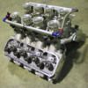
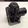
Not sure how many are running this setup, but lets hear how you setup the brake booster vacuum line, the MAP (Manifold Absolute Pressure) sensor, and the IAC (Idle Air Bypass/Control).

The single planes have a shared plenum area before the throttle body for vacuum signals, but because of the individual runner intakes there is no shared plenum to pull signals from. To pull enough vacuum for the brake booster the size has to be pretty large. I've seen one Kinsler setup that had one set of 1/8 hose and fittings running to each runner back to a shared vacuum manifold where the map sensor plugs in, then 1/4" lines to another block for the IAC. The IAC requires at least 1/4 line so that enough air can be pulled in for cold start idling. Someone mentioned not sharing these on the same block because of the IAC essentially being a controlled vacuum leak would potentially throw the MAP signal off.

IAT - Intake Air Temperature. In many EFI manifolds, one of the runners has been drilled tapped for this. Do I need to have a runner tapped or can this be run from a shared vacuum block.

Lastly how did you guys setup the brake booster line or are you running manual brakes now.
Last edited {1}
Original Post

Replies sorted oldest to newest

Hmmm.
I'm also in the middle of fitting an 8 x throttle body injection.
As well as new alloy CHI 4V heads.
There is an 3/8"NPT port on one of the manifolds intake runners, I presume for the brake booster vacuum line.
But....... is that enough vacuum?
I'm currently running a vacuum bottle next to the brake booster as previously I had issues with the engine stalling during hard low speed braking.
I suspected it was the booster sucking all of the engines available vacuum as the cam is fairly wild.
The vacuum bottle cured this issue.
Attached is a picture of whats being fitted, hopefully I will find the time this week to get the new heads on.

Attachments

Images (1)
  • Injection___heads_copy
quote:
Originally posted by Edge:
Hmmm.
I'm also in the middle of fitting an 8 x throttle body injection.
As well as new alloy CHI 4V heads.
There is an 3/8"NPT port on one of the manifolds intake runners, I presume for the brake booster vacuum line.
But....... is that enough vacuum?
I'm currently running a vacuum bottle next to the brake booster as previously I had issues with the engine stalling during hard low speed braking.
I suspected it was the booster sucking all of the engines available vacuum as the cam is fairly wild.
The vacuum bottle cured this issue.
Attached is a picture of whats being fitted, hopefully I will find the time this week to get the new heads on.


You Aussies have all the fun.
quote:
Originally posted by Edge:
Hmmm.
I'm also in the middle of fitting an 8 x throttle body injection.
As well as new alloy CHI 4V heads.
There is an 3/8"NPT port on one of the manifolds intake runners, I presume for the brake booster vacuum line.
But....... is that enough vacuum?
I'm currently running a vacuum bottle next to the brake booster as previously I had issues with the engine stalling during hard low speed braking.
I suspected it was the booster sucking all of the engines available vacuum as the cam is fairly wild.
The vacuum bottle cured this issue.
Attached is a picture of whats being fitted, hopefully I will find the time this week to get the new heads on.


Actually I'm pretty sure that 3/8" NPT port is for the IAT (Intake Air Temp) Sensor. Most modern EFI intakes have this provision in one of the runners. For an accurate vacuum reading, you have to run a vacuum block with individual 1/4" hoses running to each runner. The brake booster is a big hose though, so another person running one of these told me I would probably need to run 3/8" lines to each runner, but I want some supported feedback from others before I went from 1/4" to 3/8"

I'm running a Kinsler 3 piece yates manifold with some early C3's supposedly ported by Holman in the mid 80's for the Wood Bros. Will have them flowed first against my c302b's, then port matched to the Kinsler intake.
As far as pulling vacuum for the brake booster is concerned, I'm using an electric vacuum pump. It used to be that these were VERY noisy but with the advent of electric cars, the market has responded with very quiet, low amp, compact, vacuum pumps that are designed to provide vacuum for power brakes. I'm using an MES-DEA 70/6E2 from metricmind.com.

You don't need to mount the IAT sensor in a runner, you can mount it in the base of an air cleaner or in a velocity stack.

As far as the IAC is concerned, one school of thought is to simply live without it. You can set-up your EFI TB's to idle without it, just like you would a set of Webers. It saves A LOT of complication and potential tuning headaches. You might want to discuss this with Earl Miller, Kinsler's EFI expert. If he can't give you a definitive answer, he can certainly point you in the right direction.
Give me a few days for the picture. I'm in the process of mounting the pump in the space behind the driver's side headlamp. If you speak with Metric Mind, you'll find the price is better than the one published on their web site.

Talk to either Kinsler or F.A.S.T. regarding the MAP sensor and specific plenum sizing requirements.
My understanding is that the low vacuum is caused by a big cam having a lot of overlap and long duration. The cam I'm going to run has about .69x lift on both intake and exhaust, and around 51 degrees overlap w/260 & 265 duration. It's probably pointless that I even worry about a port for the brake booster and go the route david said with the vacuum pump.

I had to do the same thing on my mustang when I ran a big solid roller in my blown 308ci a4 motor, and swapped to a manual brake master from wilwood. It was a quality piece, but after I bled the brakes etc etc, I drove it around and it felt like the car went back in time. I'm not going that route on this car, I'm keeping the vacuum assisted brakes.
My system is an older 1980's setup.
The only pickups were the crankangle sensor, water temp, throttle position & a vacuum sensor that picks up from a small vacuum port in one of the throttle bodies.
Although the Motec has provision for other pickups.
So I'm also fitting a cam angle sensor into the distributor mount as well.

I will try the brake booster feed from one runner & see what its like.
The vacuum bottle will help.
If I have issues I can always tap into other runners to a common collector manifold.
quote:
My understanding is that the low vacuum is caused by a big cam having a lot of overlap and long duration.

Yup
quote:
The cam I'm going to run has about .69x lift on both intake and exhaust, and around 51 degrees overlap w/260 & 265 duration. It's probably pointless that I even worry about a port for the brake booster and go the route david said with the vacuum pump.

Yes you’re probably correct with that cam, however a cam that has very poor street manners in a common plenum intake can behave very differently in IR. Most notably will be improved idle where the common plenum intake was affected by reversion pulses. You might be surprised how much this can be tamed down in IR. For cams with lot’s of overlap, beware of fuel plumes in carbureted IR set ups. They can saturate filters and become a fire hazard. For IR EFI, full sequential injector timing can help somewhat but not eliminate the issue.

I’d recommend you go electric vacuum pump for vacuum accessories. Introducing the affects of common vacuum lines to your induction system can create further tuning challenges. In either case for a separate pump or manifold vacuum tap, make sure you have a high flowing, very low pressure drop, check valve to isolate your vacuum reservoir.
quote:
My system is an older 1980's setup. The only pickups were the crank angle sensor, water temp, throttle position & a vacuum sensor that picks up from a small vacuum port in one of the throttle bodies. Although the Motec has provision for other pickups. So I'm also fitting a cam angle sensor into the distributor mount as well.

The addition of a cam sync sensor will allow you to employ full sequential as opposed to phase sequential which is my preference (full) as well.

I’m going to stay out of the IR EFI MAP sensor discussion for now, but for all you speed density fans, I would pose the following question for further discussion on this thread:

What exactly do you think is being accomplished and measured by the MAP sensor plumbed to a “tuned volume”, when you can significantly change the characteristic of the signal with the size of the plumbing line and plenum volume?

IMO, if you are not going to see big changes in altitude/atmospheric pressure, you may just want to consider going N-Alpha and call it a day. Electromotive has a blend mode that is a compromise solution.

Best,
Kelly
Last edited by panterror
Kelly, no doubt you can probably alter the signal by changing the line size, so I suppose the larger line size would provide the most accurate signal and mimic a shared plenum design. Something brought up to me with a local head porter was the reversion wave from a big overlap cam throwing the map signal off as well. Something I was concerned about was the port mismatch between the IR manifold and the heads. The local porter mentioned that a slight mismatch could help reduce the wave cleaning up the signal. I'm bringing him the manifold and heads to see how much of a mismatch would be acceptable, because his idea of a mismatch could be different than what I'm looking at.

I don't foresee any major changes in the setup once I get it going, so an N-alpha map could work no problem. If I can get it to work in closed loop, the engine may run better at part throttle being able to utilize a larger map as opposed to the limited map based on just rpm and throttle position to assume load with N-Alpha.

Here are some pics mocked up on my backup cleveland with both single plane and Kinsler. Single Plane obviously fits better. This single plane could be adapted to EFI, but the Kinsler should theoretically make more power assuming I can get it matched closer. Here you can clearly see the difference between the taller SVO abc port and the more squared shorter yet wider yates port. It appears offset as well.


Last edited by hustler
after talking with Earl at Kinsler he basically said that n-alpha was probably the only solution due to the limited voltage range the map sensor will provide given the cam and the rest of the setup. Makes sense so I guess at this point I have to decide if I want the convenience of the IAC. I ran the demon with no choke and it wasn't a big deal to me, so I guess I need to figure out how bad I want it to start without holding the pedal down slightly while it warms up.
quote:
Kelly, no doubt you can probably alter the signal by changing the line size, so I suppose the larger line size would provide the most accurate signal and mimic a shared plenum design.

Large lines improve response time. If you overdo it, they can also create a lot of signal noise with a small plenum. Small lines dampen noise and worsen transient response which defeats the ability to emulate traditional speed density MAP type signal tune. You can potentially get some improved off idle and low Rs behavior but above that it all looks like WOT to the MAP sensor any way. How much time do you spend below 2krpm rpm? -About zippo for me but I live in a rural area with lots of smooth back roads and don’t do much city driving with my car nor do I care too.
quote:
Something brought up to me with a local head porter was the reversion wave from a big overlap cam throwing the map signal off as well. Something I was concerned about was the port mismatch between the IR manifold and the heads. The local porter mentioned that a slight mismatch could help reduce the wave cleaning up the signal. I'm bringing him the manifold and heads to see how much of a mismatch would be acceptable, because his idea of a mismatch could be different than what I'm looking at.

I wouldn’t rely on port mismatch to address this. For reversion pulse dampening, the mismatch would need to be smaller runner than head port window and most of those situations only enjoy some benefit if any up to a certain port velocity and then fall on their face. Aren’t you the other way around (runner bigger than port window)? I can’t really tell from your pictures but the one I can see looks like the manifold is considerably wider on one side (1/4” maybe?) perhaps A3 port width? I’d fix the mismatch if I was you. Is your intake aluminum or mag? Get some aluminum filled epoxy and have at it.

quote:
I don't foresee any major changes in the setup once I get it going, so an N-alpha map could work no problem. If I can get it to work in closed loop, the engine may run better at part throttle being able to utilize a larger map as opposed to the limited map based on just rpm and throttle position to assume load with N-Alpha.

Like I said above, if you’re going to spend a lot of time in this range, might be worth it to you but be prepared for a lot of fiddling around.
quote:
This single plane could be adapted to EFI, but the Kinsler should theoretically make more power assuming I can get it matched closer.

In a high state of tune, you may actually be able to get more peak HP out of the 4barrel open plenum than the IR unit. However, I would contend you could get more area under the torque curve in a say ~3krpm range with better street manners at low Rs going IR. Like most things, depends upon how well your selected parts play together.
quote:
Here you can clearly see the difference between the taller SVO abc port and the more squared shorter yet wider yates port. It appears offset as well.

Are these older C3s with standard Clev valve train and angles or the modern Yates C3 variants?
quote:
after talking with Earl at Kinsler he basically said that n-alpha was probably the only solution due to the limited voltage range the map sensor will provide given the cam and the rest of the setup.

Thus my previous comment that if you don’t expect to see big changes in altitude; just go N-Alpha and call it a day.
quote:
Makes sense so I guess at this point I have to decide if I want the convenience of the IAC. I ran the demon with no choke and it wasn't a big deal to me, so I guess I need to figure out how bad I want it to start without holding the pedal down slightly while it warms up.

Yup!
I prefer running a MAP sensor on anything I tune. Alpha-N is great for racing applications but I never have liked it for street cars. You wont be using as much of a MAP sensors range but it will still function. Some of the new ecu's are great for providing mixed strategies for tuning. I would probably run an ecu that has zero throttle tables and programmable outputs. As for your IAC a simple fast idle solenoid in the linkage could do the trick if tied into a temperature based output on the ECU. Heck, you might even be able to find a pulse width modulated one for even better idle control. I am a fan of baro correction as well. Mind you we have a few customers that do hill climb events so this is a must. Many of the new ECU's offer this function.
quote:
I prefer running a MAP sensor on anything I tune. Alpha-N is great for racing applications but I never have liked it for street cars. You won’t be using as much of a MAP sensors range but it will still function. ……I am a fan of baro correction as well.

So would you simply use a MAP sensor to reference atm pressure and call for the usual fuel map adjustments with TPS, temp, and other sensor inputs, or would you incorporate the MAP into an IR manifold runner/plenum scheme as discussed earlier in the thread?
quote:
As for your IAC a simple fast idle solenoid in the linkage could do the trick if tied into a temperature based output on the ECU. Heck, you might even be able to find a pulse width modulated one for even better idle control.

That would be novel for IR. Don’t think I’ve ever seen that on an IR set up. Most I’ve seen don’t even fiddle with it. In fact, most seem to just have a mechanical provision for idle and temperature coordinated enrichment scheme for warm up, but as you say, depends on the level of effort and amount of time you’ll be living in the range where you’ll benefit, and accordingly, how much effort your willing to devote to it. IAC is the next level of effort you see folks incorporate. Roush spent a boat load of time with TWM (before Borla) when they were developing the IR crate engine package. Personally, If I drove my car in traffic and round-town conditions and valued how it performed and behaved in this condition over the other end of the spectrum, I would not run nor recommend IR EFI.

I think a project incorporating IR EFI would be a great one for 5252!
Kelly asked me for my experiences, so here's my two cents. He may post my reply to him (which describes my experience with the 'blend' feature in Electromotives TEC3r), but here's some more response after reading through the thread.

EFI #1
My first go at EFI was an IR setup using TWM throttle bodies on my Pantera with a 377 Cleveland. It is a Quella/PPC setup that I got a good deal on. I did not know ANYTHING about EFI in 2000 when I installed it, so it was a real learning experience for me. i.e., I made a lot of mistakes, but figured it out in the end to my satisfaction.

It uses an ancient Haltech F9a that works just fine to this day, thank you. Biggest problem with the overall system is getting a laptop to talk to it. The last software version won't work with anything above W98... I've been using a freeware software known as 'DOSBOX' successfully.

The F9a is setup for TPS only (or Alpha-N as some call it). The MAP sensor I have is used for barometric correction.
I have had very, very few problems with this setup. I kept blowing the injector fuse initially. Haltech and Quella both said put a bigger fuse in... no problems since.
I had a side pull linkage which worked, but was super sensitive at low rpm ranges. Kinda' difficult to drive 'nicely', but with some perseverance, I got it to work pretty good. I drove the car daily to work and at the track.
With a carb, the car would NOT idle below 1000rpm; happier at 1200. The IR EFI made it idle so nice I was disappointed. Gone was my rumpity rumpity cool idle. But the low and mid range response improvement was amazing.
Recently, Mike Trusty helped me change the linkage to a more gradual center pull setup. Big improvement.
I use cylinder #2 for the brake booster. It works fine. I've never found any reason to change the setup although many people claimed it would not work. I did at one point think #2 was running slightly lean, but that turned out to be the injector being lower output than the rest. I sent the injectors off to Marin and they serviced them and matched them up. No more problem.
I will run this 'ancient, antiquated system' until it dies. It works too well to change it.
Oh, and I still use a distributor for the ignition.

EFI #2
IR EFI on my GT40. 427 Windsor, 351B heads, IR manifold from Kelly.
TWM throttle bodies, Electromotive TEC3r ECU, MSD DIS-4 with coil on plugs for ignition.
All throttle bodies tied via vacuum lines to a single plenum and a MAP sensor.
MAP sensor and TPS sensor together using the 'blend' facility of the TEC3r.
No brake booster...
See the response I gave to Kelly for the saga I had with the blend functionality.
Car is running a lot nicer now since I moved to more MAP sensor input.
This installation was a real bear... The Pantera has LOTS of room compared to the GT40. Things are tight on the GT40. Harness routing was a challenge, sensor installation was a challenge, a bad harness gave me fits for months...

I'm quite happy with it now and am busy backing out my 'artificial' compensation now that the response is much improved.

Any questions, let me know.

Kirby
When I saw this post I recalled from recent correspondence with Kirby that he had been the route. I also have a Tec3r ECU and both Kirby and Mike Trusty run them with IR EFI. When I asked Kirby about his experience with blend mode and the factors that related to this thread, here was his reply as he referenced above. Bottom line fellas, doing it can be a lot different experience than talking about it.

quote:
Background: I got the Electromotive TEC3r and EFI setup I have on the GT40 from Mike. EM and Mike and the manual all strongly recommend not to use the MAP sensor with IR setups for the acceleration coefficients and I also had recommendations to use TPS as the most effective sensor in the 'blend' setup.

So, I was running blend at 95% in the lower rpm's dropping to 80% the rest of the way. Car would run great at idle, great at full throttle and was a damned pain at cruise or off throttle. I put up with it for over three years and then recently, I did the opposite.

My logic was that the TPS voltage was barely moving off idle even though the butterflies were cracking open a lot. It doesn't take much movement of the throttle bodies to accelerate from 55mph to 65mph... :-)

If the TPS is barely moving, how the heck can the ECU know anything or do anything about it?

I turned on the MAP acceleration function and dropped my blend down gradually. I am now at 65% on blend and it's a different car.

Previously, it would pop and spit and cough every time I tried to come off a stop light or ease into the throttle when at cruise.. I was adding serious fuel just off throttle in the VE table to try and compensate and then taking it right back out just above that. Trying to create my own throttle pump, in other words.

I am now pulling all that back out of the VE table since the car is a dream to drive now and is running a little too rich.

Two other things were happening to me... the cool pretty red plastic? hoses that ran from each throttle body to the plenum sitting in the center of the manifold were popping off the throttle bodies, making that cylinder run lean, of course, and seemed to be collapsing or at least getting really soft. I have replaced all of them with thick black rubber vacuum hose.

Amazing how my overall feeling towards the car has improved. Now I can concentrate on other little issues.

Hope that helps. I am still in the state of 'tuning' though, but it's all better now. :-)

Kirby


Thanks for that input Kirby.

I sent the same message to Mike Trusty. He has forgotten more than I know about IR EFI.....and that's because he knows a lot....not because his memory is going bad Big Grin

Best,
K
Last edited by panterror
Kirby, what size are the fittings/lines you used on the gt40 to the shared block? 1/8 is small, most people said if you use an iac you need a 1/4" minimum line running to the shared block. Mind if I ask where you got the vacuum block as well? Did you mount the IAT in the ramtube/horn as Earl suggests at Kinsler vs tapping a hole and running it in a runner on the manifold? Earl was pretty adamant about not running it on the manifold due to heatsoaking in idle conditions, but I know on the ford 5.0 manifolds they all ran it on one of the runners in the stock and aftermarket cast manifolds.

Kelly, the c3's are early '84 castings so they are the canted valve version, not the later yates version with just the intake canted.
quote:
So would you simply use a MAP sensor to reference atm pressure and call for the usual fuel map adjustments with TPS, temp, and other sensor inputs, or would you incorporate the MAP into an IR manifold runner/plenum scheme as discussed earlier in the thread?


I would run a standard collection manifold feeding from all TB's. With that I would run a Haltech ECU or similar that has a Zero throttle table. With big cams and low vacuum getting a car to idle at a decent AFR is tough with a single VE map as the engine idles at a vacuum level so close to atmospheric. The zero throttle table is substituted in when the throttle is closed so the idle can be tuned seperately of the main VE table regardless of low vacuum. As for baro the Haltech can use a dual MAP sensor. One is built in and if one is added the built in sensor can be used for real-time baro. F.A.S.T as well as megasquirt sample the baro before the engine is started and use that as reference. Good for drag racing but not as good for big elevation changes as the ecu has to be shut down and restarted to get another baro reference. If you are running an air filter assembly I would plumb the AIT sensor into that. If not I just mount them into one of the ITB's.

quote:
I think a project incorporating IR EFI would be a great one for 5252!


Funny you mention it, we did an EFI install on a Devin C that is out for an exhaust but will be returning soon for some finishing touches. Its running a Corvair motor with ITB;s controlled by a SDS ecu (not my choice but will do the job). We hope to have it tuned and out to the paint shop soon.
quote:
Posted Mar 2, 7:25 PM Hide Post
Kirby, what size are the fittings/lines you used on the gt40 to the shared block? 1/8 is small, most people said if you use an iac you need a 1/4" minimum line running to the shared block. Mind if I ask where you got the vacuum block as well? Did you mount the IAT in the ramtube/horn as Earl suggests at Kinsler vs tapping a hole and running it in a runner on the manifold? Earl was pretty adamant about not running it on the manifold due to heatsoaking in idle conditions, but I know on the ford 5.0 manifolds they all ran it on one of the runners in the stock and aftermarket cast manifolds.


The lines are 1/8" standard vacuum hose. The lengths are very short, so I really can't see why you'd need bigger... but then, I don't have an IAC nor do I have any experience with one.

The vacuum block or plenum came from TWM (he sold out to Borla last year) and the 'box' has the progressive linkage wheel mounted on top of it. You can just kinda' sorta' see it here.
http://web.mac.com/kirbyschrader/GT40/EFI.html

Not sure what you mean by 'IAT'? I don't use an IAC on either car, as I noted above.

If you mean the vacuum hose for the brake booster on the Pantera? It is just a drilled and tapped hole with NPT threads. The hole is in the manifold itself just below the throttle body mounting surface. I can take a picture tonight if it would help.

If I ain't even close to what you're asking, let me know. Your next question seems to indicate that I don't understand... :-)

If you read my previous diatribe, you will note that I say on one car, I use TPS only. On the other car, I say that didn't work. Every system is different, from what I've seen.

We've got a guy here in town who put a IR system with a TEC3r on his Pantera and although it was running and working fine, after some other work on the car being done, he can no longer talk to the TEC3r. The ECU works fine in my GT40 with my computer and his computer. He takes it home and as soon as he starts the car he loses comms.
We've been through all kinds of troubleshooting, but it seems I'll have to go down and help him try to find out what's going on.

Hope that helps,
Kirby
Blaine, Kirby, and Kelly thanks for your input, definitely helping me decide which way to go.

Kirby, I was curious about the line size because another local recommended stepping up the size to 1/4" if I planned to use the IAC. I've seen most setups use 1/8" for the MAP sensor etc. I may still try to run it remotely with an adapter I found from accufab off the 1/4" tree. If it doesn't work it doesn't work. I can always swap the cam out later and get one made to provide some more vacuum, will have to see how much power it makes anyway. I ran an IAC on my mustang with a big solid roller which didn't provide enough vacuum to support the vacuum assisted brake booster but was able to get it to idle cold very well and hold 1100 rpm to keep the lifters lubricated with a gen6 batch fire with a VIC controller. But that was using a shared plenum sheetmetal upper where the signal was as good as it was going to get.

http://www.streetfire.net/vide...-with-pax_122768.htm

http://www.streetfire.net/vide...-with-pax_122770.htm

IAT Intake Air Temperature sensor.

Here is the alcohol, aluminum rdi, A3 headed motor the local is running in his altered. One hell of a clevor Wink


quote:
Originally posted by Panterror:

IAT = Intake (or inlet) Air Temperature sensor

K


Ahhh..... I call it MAT, Manifold Air Temperature, since both Haltech and Electromotive call it that.
Smiler

Both of my cars have the IAT/MAT located on the bottom of the right side lower air filter plate between cylinders 1 & 2.

That's a hell of an engine in those pictures!

Kirby
Agreed, quite the nasty motor. If you will be running the IAC to a common manifold shared with the MAP sensor be sure to keep the combined size of the feed lines from the ITB's to the vacuum manifold a bit larger than the volume of the IAC. Otherwise you may end up with pressure variances caused by the airflow changes of the IAC valve which will have you chasing your tail trying to get it idling properly.
Thanks for the heads up blaine, I'm reviving this as I'm getting parts in. This shows you how fast I'm moving on this Wink I finally found something suitable to use. I found an enderle fuel distribution block which can also be used as a vacuum block. It has enough ports to support the brake booster, IAC, and MAP. I'll try to cobble something together in coming days. Still debating where to mount the IAT. It seems to make sense to get the IAT as close to the chamber as possible. But on this intake the injectors sit fairly high and close to the throttle blades, so I don't want to douse the IAT with fuel. It will have to be upstream, but I want it before the throttle blade. Will have to see how much clearance I have to tap a hole. Blaine or anyone else, have you any detrimental effects having IAT mounted before the throttle blades? It seems like at idle when the blades are almost closed the air after the blades would get warmer vs the air incoming before the blade. Maybe this is insignificant. Just concerned that any tables like air temperature correction tables which add or pull fuel based on incoming air temp may be adversely affected and less accurate.

Kelly mentioned that the size of the "vacuum" tubes is a factor in tuning the system.

I'm still a neanderthal and working with carbs so I don't mean to intrude on your discussion, but I need to acquire significant information when it is at hand, so, at what point does the size of the tubing become a balance tube, effect the overlap reversion pulses and act as a plenum?

I'm thinking that would need to be very large, 3/4" or maybe even larger?

Anyone come across that number yet?
As I mentioned before, a small line and large plenum dampens MAP signal variation and increases response time while big lines and small plenum does the opposite. The best test of your combination is to sample the MAP signal frequently. If you have ability to record MAP signal on you ECU, set to max sample rate and look at the max and min signal while operating the engine at constant RPM (if you can). An oscilloscope or recording DMM can also do the recording work. If the amplitude of the MAP signal significantly varies, say more than 10-20%, and the period of time in which you can measure max & min MAP signal is comparable to your ECU sample rate, you could probably due with some additional dampening. For convenience, an easy way to do this is to simplysimply run a line to a remote volume than you can easily change; sometimes the line volume itself is sufficient. This is an easy way to experiment and also can help with packaging by getting the hardware out of the valley of your intake. You may also wish to consider how having your vacuum brake booster attached the same vacuum circuit might affect your MAP signal, especially since it’s likely your foot will be on the brake when your engine and car are at low speed and precisely when you want a reliable MAP signal. This is why I’ve mentioned either a large check valve isolated accessory vacuum plenum or a completely separate vacuum pump driven circuit. In addition, IAC operation will also affect the MAP signal.
From what you are saying, I am thinking that it would be better for MAP signal strength to have an additional Power Brake check valve in line closest to the vacuum block as you can get.

This would eliminate, or isolate the volume of vacuum in the line to the booster valve?

I suppose might make that line to the brakes act as a vacuum storage reservoir as well?
quote:
Originally posted by PanteraDoug: From what you are saying, I am thinking that it would be better for MAP signal strength to have an additional Power Brake check valve in line closest to the vacuum block as you can get. This would eliminate, or isolate the volume of vacuum in the line to the booster valve? I suppose might make that line to the brakes act as a vacuum storage reservoir as well?


Yes, but then you have the pressure drop of two check valves. Depending upon the valve that may not be a big deal but I think you’re better off with the valve being closer to the vacuum source. The OE valve on a Pantera is on the reservoir fitting. The simplest thing to do is just add a vacuum reservoir as close to the booster as possible and this is usually fine if you are in a situation where your available vacuum is marginal which will probably work for most street cars. This just provides you more cycles of your booster/servo until you ultimately engine conditions can resupply the reservoir. The thing to remember is those little hoses from each runner that are sufficient to pull vacuum on a small MAP plenum may look very small when a brake booster demand thus significantly alter the apparent MAP signal. A little booster draw can be misinterpreted by ECU as onset of engine load.

Some engine combos will never provide enough vacuum, plenum or not, and for that you need a belt or motor driven pump.

quote:
Originally posted by Hustler: kelly, so has it been your experience to try it first with the iac, map, vaccum booster all on the same circuit depending on application, or that you have always separated the circuits in applications you have worked on or been exposed to prior?


You can go both ways but if you have erratic MAP signal with everything attached to the vacuum circuit, how do you know the culprit? Is it insufficient line plenum sizing? Brake booster interference? IAC? The downside is investing tuning time in a configuration different than you ultimately prefer to run. You might get lucky and be fine right out of the chute with all but if not you’ll just start having to pull those other devices from the vacuum circuit. Surging at idle is a pretty common thing to combat and it’s usually caused by some feedback loop between the IAC and the ECU MAP signal processing logic and response rate. You just have to experiment. Of course, you have all the other injector and sensor driven enrichment schemes to mess with too. I’m not one to talk because I have a system that I’ve been struggling with for some time, though I suspect it’s a completely unrelated problem because it’s not running worth a darn under any condition at the moment.

Best,
K
Yeah i'm not thrilled about the prospect of running a mechanical/electric vacuum pump on a street car due to the limited life of the pumps. I realize there is the added benefit of being able to pull vacuum out of the crankcase as well, but I will try the tank next to the booster first if needed. Won't know till I get there though. I suppose I'll just give it a go as is and adapt as I go. just don't want to pull the intake off again to re-drill/tap a runner to separate the map sensor. Not excited about check valves either, but see how they could be integrated.


I've dealt with surging on another aftermarket programmable ECU. The surging I've dealt with on my blower mustang. the problem with that older ECU/software is the cell range is fixed for setting values. The resolution is cut in half going from a 1 bar map sensor to a 2 bar, then 3 bar its cut again. Because of this, while using the 2 bar map sensor many of the tuning areas based on map/load, I have very little resolution area to modify changes for street cruising/idling where the engine is out of boost and pulling vacuum, which is most of the time. I don't believe the FAST Classic is limited to this scaling, but will have to see.
Post
×
×
×
×
Link copied to your clipboard.
×