I've read many of the posts about trying get fresh air in the engine compartment. I'm envious of the one's who have been able to effectively pipe in fresh air. Makes me wish I had GT5 / GTS flairs to try and scoop up some fresh air and redirect it.

I don't really use the A/C. I was wondering if disconnecting the AC Evaporator and hooking up a blower to blow out hot engine air from the vent would have any effect? I have noticed that even after mild runs the engine bay is cooking hot. Is there an easy way to get some of this hot air out?

I have the engine out and I thought about trying to scoop some from the bottom of the car, but wasn't sure if that would have any success. You probably wouldn't have to weld in but a small piece metal to get just a little more air flow in the engine bay. I'm not talking about blowing off the engine lid or anything like that, but any amount of airflow would have to help. Could you pipe any in from the bottom front of the engine to have any effect?

Even if I don't do it on this car, I'm already planning on what I will do on my next build (GT4/GT5/GTS).
Original Post

Replies sorted oldest to newest

quote:
Could you pipe any in from the bottom front of the engine to have any effect?

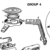
In fact, the later cars did have a scoop mounted low on the right side to supply air to the air cleaner.

BUT, when you consider how dirty that air is and how warm - it is just inches above the roadway, usually hot black tarmac and dirt-strewn - you might not WANT that air in your engine compartment.

Larry

Attachments

Images (1)
  • Picture_4
I thought about that, but wasn't sure what the impact would be. There just doesn't seem to be very much air movement back there. I don't know - maybe I'm fooling myself as I've had other front engine cars that were plenty hot under the hood and that's with air coming in from all over the place - grill, air dam, radiator, etc.
FWIW, the Pantera by design already 'sucks' air from under the car up through the engine compartment and out the engine screen at top. The suction is so great that it sucks gravel and dirt right off the road and deposits it onto the inner frame rails in the engine compartment and the rear deck lid.

I'm actually interested in limiting the air/dirt flow through the engine compartment by use of a bellypan or lower covers for the front of the engine compartment. I'll experiment once my new engine is back in the car.
Guys often confuse "ram air" with "cold air". They are two different things actually.

"Ram air" is pressurized air, boosting horsepower by feeding the motor denser pressurized air. To catch pessurized air that will increase horsepower you need two things, a scoop that sticks up high enough to catch "clean air" and enough forward velocity (speed) that the air pressure will be significant. Unless you are traveling real fast, don't worry about "ram air". If you stick a scoop 12 inches above the car, the horsepower gain at 60 mph would be negligible, certainly not worth putting up with an ugly scoop. You've all seen the Pantera roof-line scoop that travels up from the motor, bends around the roof of the car, follows the roof line forward and has an opening right at the top of the windshield. The air accelerates as it passes over the windshield, that scoop takes advantage of that. OK for a race car, but I doubt many of us would want that contraption on our pretty little Italian sports cars. The other drawback of "ram air" is that its biggest advantage only occurs at wide open throttle. If the throttle butterflies are partially closed, and the intake manifold is under vacuum, the air being supplied to the motor is not much denser.

"Cold air" takes advantage of the fact that cold air is denser than warm air, horsepower increases 1% for every 10 degree F drop in intake air temperature. Cold air is not dependent on the speed of the car or the position of the throttle butterflies, therefore cold air will help any vehicle, including vehicles driven by old slow guys like me. Cold air can be picked up anywhere, but I would advise against ducting cold air from the rear of the car, because the rear of the car has a tremedous low pressure zone behind it when the car is moving forward. A simple NACA duct on the side of the car would work perfectly; NACA ducts are available from race parts suppliers like Pegasus.

-G
Last edited by George P
quote:
because the rear of the car has a tremendous low pressure zone behind it when the car is moving forward

This has been common belief in Pantera Land for many years now, but some actual testing recently done by Panteras NW member Matt seems to disprove this belief.

He has run several various tests, various speeds, with the stock A/C condenser/fan unit in place, and without them in place.

Here is a link to one of his Youtube videos. You can find links to the others at this link, also.

http://www.youtube.com/nwpantera#p/u/3/JFruPmLkVkk

Matt posted all this, and we had quite the discussion, over at the POCA forum.

Keeping current on both forums, I believe, is well worth the additional time.

Larry

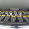
This is with fan sucking in (as stock). Note the plastic flaps are uniformly being held tight to the inlet grill.

Attachments

Images (1)
  • Picture_10
Thanks for the link Larry ...

Love stuff like this.

For me, based on the videos, (without having all the test details), there appears to be quite convincing evidence that the best configuration is to have the condensor fan sucking air in to cool the condensor coil.

What can be said ? The DeTomaso engineers did a good job. So, "if it ain't broke, don't fix it !"
quote:
air flow through the a/c condenser

Sorry G., wasn't trying to change topics. But while Matt's testing was for the A/C condenser, since it dealt with the exact same area you mentioned when you wrote:
quote:
I would advise against ducting cold air from the rear of the car, because the rear of the car has a tremendous low pressure zone behind it when the car is moving forward.

I felt the new info was appropriate for this discussion.

If there is plenty of available air for inflow to the condenser, it follows there is also plenty of air for inflow to the engine.

And again, this does go against standard Pantera Land belief, but if you view all the videos in all their variations, it sure seems there is not any lack of air at the rear of the car, at speeds up to 115mph.

Larry
Don't get me wrong - I would love a ram air setup, but I'm not willing to part with the side windows. While I appreciate the ducting that can be done while removing the windows, it is just not worth the trade-off in looks. Maybe if I was racing it, but for a street application I personally don't care for the "ears" whether low or tall profile.

My real issue was just the heat build up in the engine area as well as not necessarily having even marginally cool air flowing into and around the engine - never mind a ram-air or cool-air setup into the carb. My question was really more centered around if you could duct some air into the engine bay or exhaust it out through the a/c vent area to get additional air flow in the engine bay - just trying to take a realistic first step to get any air into / out of this area.

I did run across the POCA articles last night while doing a bit of research and I have to say Kudos to the gentlemen going the extra mile trying to figure out airflow into and out of this area. While my scientific friends would probably not be 100% sold, I'm a realist and can operate on good assumptions verse 100% verifiable facts. The You-Tube videos are great and exactly what I'm looking for.

I too have the same question - which is more efficient? To pull the air in via the A/C vent or to exhaust it this way. I am curious if you exhausted air this way, is going to come in from the engine screen or via under the car or probably both. Someone mentioned a belly pan and while I doubt you would want to block all this air, if you decreased the opening some and exhausted out the back with a shroud, you might be able to pull in more air from the engine screen area. You probably wouldn't get enough air to make much of a difference in the air coming into the carb, but you could get a flow of air though the engine bay which seems to be lacking today. It would be interesting to hook up a smoke / fog machine in the engine bay to see where it vents even under moderate speeds.
Apples and Oranges

The videos indicate that the difference in pressure between the engine compartment and the area immediately behind the vehicle is small enough that the a/c condensor fan can move air in either direction while the vehicle is moving. That's a cool bit of information, and yes it more or less resolves an old debate.

The videos do not indicate what the absolute pressure behind a moving Pantera is however. They neither prove or disprove my comment, that a negative air pressure zone exists behind a moving vehicle. Every blunt shaped vehicle and every vehicle with a Kamm-tail has an area of low pressure immediately behind it while the vehicle is moving.


Air in contact with the body of a vehicle creates drag in the form of friction which acts upon the vehicle as it moves through the air. A low pressure zone behind a vehicle also creates drag. A vehicle with a blunt shape creates a large area of low pressure behind it as it moves through the air. That low pressure adds significant drag to the vehicle, it slows the vehicle down. Paul Jaray developed streamlined car body work in the 1920s. His innovative body design featured a low-profile teardrop shape with a long tail to minimize the air resistance of passenger cars. The long tapering tail bent the air, it induced the air into following the gently tapering bodywork of the vehicle, thus preventing the formation of a negative pressure area behind the vehicle. But that long tapering tail had no practical use, it added to the length of the vehicle, it added to the weight of the vehicle and it added to the expense of building a vehicle.


Researchers working under the direction of Wunibald Kamm and building upon the work of others, developed a design principle known as the Kamm-effect, offering a more practical method for building an aerodynamically efficient body profile. (from the wiki) "While the realities of fluid dynamics dictate that a teardrop shape is the ideal aerodynamic form, Kamm found that by cutting off / flattening the streamlined end of the tear at an intermediate point, and bringing that edge down towards the ground, he could gain most of the benefit of the teardrop shape without incurring such a large material, structural, and size problem. The airflow, once given the suggestion of the beginning of a turbulence-eliminating streamlined teardrop tail, tended to flow in an approximation of that manner regardless of the fact that the entire tail wasn't there ... According to the classic definition the tail should be cut off where it has tapered to approximately 50% of the car’s maximum cross section, which Kamm found represented a good compromise - by that point the turbulence typical of flat-back vehicles had been mostly eliminated at typical speeds."

In other words, a Kamm tail minimizes the size of the low pressure area behind a vehicle moving through the air to the point that the drag on the vehicle created by the low pressure area approximates (doesn't equal) the drag that would have been created by the friction of the air moving over the tail itself.

The Kamm-tail or Kamm-back was first applied to automobiles in 1949, and didn't come into popular use until the 1960s. Its the fast back with a flat tail look that became so popular with sports cars and performance cars, including the Pantera. It is so common today that the design is taken for granted, nobody refers to it as a Kamm-tail any longer.

As a Kamm-tail car moves through the air it pushes the air out of its way, it slices through the air, and the wake in the air behind the vehicle will take the shape as though the vehicle had a long tapering tail, and in that area where the long tapeing tail would have been is a low pressure area instead. That is the low pressure I am referring to.

Aerodynamics ain't my baliwick boys, so I hope I've presented the information in an understandable way.

-G Smiler
Last edited by George P
Sounds crazy, but one of the best videos that I've seen that shows this effect is a Mythbusters episode where they covered a Taurus in clay and then dimpled it like a golf ball. Don't remember the entire video, but by dimpling the car, they increased / decreased (I don't remember which) the air gap behind the car and actually increased the gas mileage. There is no way I would ever have thought this to be the case as I had always assumed a slippery design would be more efficient. My point is that the "air bubble zone" behind the car should be understood more - especially if we (I) want to flow more air through the engine bay.

I've seen the various videos with the strings on the sides and back of the car and now on the back of the a/c vent area, but has anyone checked the airflow in or out of the air screen / off the back window? To your point, the inherent design off the back window would cause this same effect to a degree - correct? So what does that mean? Does it make the air more neutral so that it could be moved in or out of this area (depending on need) OR does it already create a suction in a given direction?

The reason that I'm asking is I'm not sure which way the air is moving through the engine screen and if you could create a draw or suction that draws air into the engine from the top, it could alleviate some of the dust / dirt issues drawing air from the bottom of the car potentially creates while still cooling the engine. Based on the heat build-up I've seen, it doesn't seem like there is a given air flow direction in the engine bay, but my expectations may be unrealistic.
> Air in contact with the body of a vehicle creates drag in the form of friction
> which acts upon the vehicle as it moves through the air.

For a blunt shape (in practice, anything other than a slender airfoil) like
an automobile, the skin friction drag is small compared to the drag caused by
separation. The profile drag of an object can be spilt into two components:

Cd = Cdf + Cdp

where

Cd = profile drag coefficient
Cdp = pressure drag coefficient due to flow separation
Cdf = skin friction drag coefficient due to surface roughness
in the presence of laminar/turbulent flow

The drag which comprises the Cdf component is caused by the shear stress
induced when air molecules collide with the surface of a body. A smooth
surface will have a low Cdf. Also, the Cdf is lower for laminar flow and
higher for turbulent flow. Cdp, on the other hand, is caused by the
fore-and-aft pressure differential created by flow separation. Usually,
Cdp is lower for turbulent flow and higher for laminar flow. In many cases,
inducing turbulence will dramatically decrease the pressure drag component,
decreasing the overall drag. Airplanes use this trick all the time.

However, it is the skin friction that causes the flow to separate which leads
to the pressure drag. If a symmetric shape like a cylinder were frictionless,
it would have no drag. Back in the 19th century, when scientists were just
beginning to seriously study the field of aerodynamics, an interesting
observation was made with respect to the drag of a cylinder. Since a cylinder
is symmetric front-to-back (and top-to-bottom), their early theories predicted
it should have no drag (or lift). If you plot the (theoretical) pressure
distribution along the surface of the cylinder (remembering that pressure
acts perpendicular to a surface) and decompose it into horizontal (drag) and
vertical (lift) components, you'll find that the pressure on the front face
of the cylinder (from -90 to +90 degrees) and the pressure on the rear face
(from +90 to +270 degrees) are equal in magnitude but opposite in direction,
exactly cancelling each other out. Therefore, there should be no drag (or
lift).

However, if you actually measure the pressure distribution, you'll find
there are considerably lower pressures on the rear face, resulting in
considerable drag. This difference between predicted and observed drag
over a cylinder was particularly bothersome to early aerodynamicists who
termed the phenomenon d'Alembert's paradox. The problem was due to the
fact that the original analysis did not include the effects of skin
friction at the surface of the cylinder. When air flow comes in contact
with a surface, the flow adheres to the surface, altering its dynamics.
Conceptually, aerodynamicists split airflow up into two separate regions,
a region close to the surface where skin friction is important (termed the
boundary layer), and the area outside the boundary layer which is treated
as frictionless. The boundary layer can be further characterized as
either laminar or turbulent. Under laminar conditions, the flow moves
smoothly and follows the general contours of the body. Under turbulent
conditions, the flow becomes chaotic and random.

It turns out that a cylinder is a very high drag shape. At the speeds
we're talking about, a cylinder has a drag Cd of approximately 0.4. By
comparison, an infinite flat plate would have a Cd of 1.0. Note that
this is not a theoretical limit. A rectangular beam will exhibit flow
separation at each corner and can have a Cd in the range of 2.0. An
efficient shape like an airfoil (that is aligned with the airflow, i.e.
is at 0 degrees angle of attack) may have a Cd of 0.005 to 0.01. Think
about what this means. An airfoil that is 40 to 80 inches tall may have
approximately the same drag as a 1 inch diameter cylinder.

Luckily, there are easy ways of reducing a cylinder's drag. Another thing
the early aerodynamicists noticed was that as you increased the speed of
the air flowing over a cylinder, eventually there was a drastic decrease in
drag. The reason lies in different effects laminar and turbulent boundary
layers have on flow separation. Laminar boundary layers separate (detach
from the body) much more easily than turbulent ones. In the case of the
cylinder, when the flow is laminar, the boundary layer separates earlier,
resulting in flow that is totally separated from the rear face and a large
wake. As the air flow speed is increased, the transition from laminar to
turbulent takes place on the front face. The turbulent boundary layer stays
attached longer so the separation point moves rearward, resulting in a
smaller wake and lower drag. For a cylinder, laminar flow separation may
occur at 82 degrees (with the leading edge of the cylinder at 0 degrees)
and yield a Cd=1.2. With a turbulent boundary layer, flow can stay attached
to around 120 degrees, resulting in a decrease in drag of Cd=0.3. The same
effect occurs for similarly sized sphere which can have a Cd=0.5 under
laminar conditions and a Cd=0.2 under turbulent conditions.

The location along the body at which the flow transitions from laminar to
turbulent determines the critical Reynolds number. Below this number, the
flow is laminar, above it's turbulent. The Reynolds number is defined as:

Re_x = (Rho * V * X)/Mu

where:

Re_x = Reynolds number at location x (a dimensionless quantity)
Rho = freestream air density
V = freestream flow velocity
x = distance from the leading edge
Mu = freestream viscosity, a physical property of the gas (or liquid)
involved, varies with temperature, at standard conditions mu is
approximately 3.7373x10E-07 slug/(ft*sec) for air.

Since the Reynolds number varies linearly with the location along the body
and with velocity, the faster you go, the farther forward the transition
point moves. At cruising speed on a typical jet airliner, only a small region
near the leading edge may be laminar. Slow speed gliders with very slender
(but still with rounded, blunt, leading edges) may maintain laminar flow over
most of the wing surface but this is not the case for most practical aircraft.
Note that glider wings are typically designed with very short chord lengths
(x distances) to help promote laminar flow. Laminar flow is desirable when
there is no pressure separation.

You don't have to rely on high speeds to cause the bondary layer to "trip"
from laminar to turbulent. Small disturbances in the flow path can do the
same thing. A golf ball is a classic example. The dimples on a golf ball
are designed to promote turbulence and thus reduce drag on the ball in
flight. If a golf ball were smooth like a ping pong ball, it would have
much more drag. If you look closely, you'll notice that some Indy and F1
helmets have a boundary layer trip strip to reduce buffeting. It seems odd
but promoting turbulence can reduce buffeting by producing a smaller wake.

Another consequence of skin friction on a cylinder is that you can generate
substantial lift with a spinning cylinder. By spinning a cylinder you can
speed up the flow over the top and slow down flow under the bottom, resulting
in a lift producing pressure differential. I think this phenomenon is known
as the Magnus effect. BTW, the exposed spinning tires on F1 and Indy cars
are *huge* sources of drag.

> Paul Jaray developed streamlined car body work in the 1920s. His innovative
> body design featured a low-profile teardrop shape with a long tail to
> minimize the air resistance of passenger cars. The long tapering tail bent
> the air, it induced the air into following the gently tapering bodywork of
> the vehicle, thus preventing the formation of a negative pressure area
> behind the vehicle.

Hungarian engineer Paul Jaray was the first to promote the full-on
teardrop shape for an automobile. Jaray had designed a new series of
Zeppelins that featured the teardrop shape and applied his ideas to
automobiles, applying for a patent in 1922. Jaray tested a series of
streamlined automobiles in the Zeppelin work's wind-tunnel in
Friedrichshafen, achieving drag coefficients as low as 0.2. He went
on to design a variety of aerodynamic bodies for Tatra, BMW, Benz,
Adler, Mayback, Audi and Hanomag and influenced a number of others.
Chrysler was forced to pay royalties for the Airflow to Jaray, as was
Peugeot (for the 402). IIRC, the Tatra T87 was designed by Hans Ledwinka
with the body based upon proposals submitted by Jaray. Ledwinka's Tatras
were rear engined (the T87 was an OHC V8 and the T97 was a flat four) and
air cooled and the designs would heavily influence Ferdinand Porsche.

Jaray's patent was contested by another aeronautical engineer, Edmund
Rumpler but was ultimately upheld. Rumpler had debuted a mid-engined,
aerodynamic automobile (the Tropfen) at 1921 show in Berlin. Benz used
Rumpler's ideas in a 1923 race car but Rumpler returned to aviation.
Rumpler was later arrested by the Nazis because he was Jewish but was
protected by Goering who knew of his aircraft designs. Rumpler's
design was wind tunnel tested in the late 1970's at VW and recorded a
Cd of 0.28.

While aerodynamically efficient, the Jaray teardrops were long and not
always easily applied to practical shapes. Based upon experimental
research conducted on buses, Reinhard Koenig-Fachsenfeld applied for
a patent on the chopped tail as a practical alternative. At around the
same time, Professor Wunnibald Kamm (head of the Automotive Research
Institute at Stuttgart Technical College) published a textbook that
described a similar truncated tail. Fachsenfeld was persuaded to sell
his patent to the German state and Kamm was funded to develop the concept.
Another university professor, Everling was onto the same idea and his
design was among those tested by Kamm. Kamm's research showed that a
properly truncated Jaray tail had less drag than a shortened tapered
tail. The full length tear drop is still a lower drag shape, of course.

When fairing in and truncating the tail, you want to do it in a manner
that raises the base pressure (the pressure acting on the aft end of
the vehicle) while making the base area (where the pressure acts) as
small as possible. There's a point of diminishing returns where
increasing the tail length has progressively less effect. Kamm's
research led him to the conclusion that you should find the point where
the tail is half as wide as the maximum width of the vehicle and cut it
off there. This Kamm truncated tail is what Pete Brock applied to the
Cobra Daytona from above and from the side, you'll see it tapers in both
dimensions. Fairing in the Pantera sugar scoop will help in one dimension
only so will not be as effective as a true Kamm tail.

Somewhere around here I have a copy of "The Aerodynamics of Land Borne
Vehicles" which details some of the early wind tunnel research on cars,
trucks, and trains.

Dan Jones
If I'm allowed to...

Related to the above mentioned aerodynamic and airflow experiments, I once found this a cool article and experiment:
http://www.aerocivic.com/

If my post is considered as being way too off-topic, then feel free to remove it again - you won't hurt my feelings Wink

Actually, since the AC got removed from my car, I've been wondering just like inhotwater about a way to influence motor compartiment temp - e.g use an additional fan in the back to do so...
Wires on old airplanes (cylinders) were huge drag creaters. As was said they have drag many times of an airfoil. On top of this a lot of simple fairings on aircraft have been known to give racing aircraft 50+mph increase in speed.

But what is speed with out control. You build an airfoil like they did with the AMX-3 and guess what; the wheels come airborne around 100mph.

If the reduction of drag is the only thought, then you want to taper the rear like an airfoil as long as possible and delay the separation to avoid turbulence.

I have given this a lot of thought to aerodynamics in my car and is something I want to play and test when I get it together. I have been watching guys put tassels on cars to test aerodynamics which frankly were too long. They get out of the boundary layer and are influenced by other air which makes the test less then useful.

The approach to my car was not as much about a reduction of drag as it was keeping it planted on the ground. I laid the radiator down, closed off all air going under the car. I ducted the air out the hood.

I also built the belly pan to help smooth the air under the car. A diffuser would be the next step but I doubt I will get that far.

What I would like to do is take what I have and test the effects. To do so my plan (to start) is taking information from 2 things. One is simply putting a variable pot on the suspension with a display to look at (and other info) real time and a computer to log the info when I feel like playing with it. The info would be the suspension height compared to speed. It would be one way to measure the effect of the wind.

Second I want to datalog pressure from specific locations at speed.

The scoops on the side will not pull air in on their own but fans to oil coolers and such will pull the air in. I am curious how the fans pulling the air in will delay the separation. I also have an idea for VG's which will keep the air against the car possibly making the vents work without fans.

The golf ball dimple concept is a neat idea which has been played with from time to time. I think car builders have a hard time getting past a car which looks like a golf ball.

On a truck they tested they also found a truck with a netting for a tail gate or a tail gate up got better gas mileage then with the tailgate down. That went against everything we can envision but it shows the complexities.

It's all fun. If you didn't have anything to do when you got up in the morning what would you do?
Last edited by comp2
Post
×
×
×
×
Link copied to your clipboard.
×