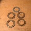
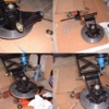
in the process of tearing down my rear suspension for rejuvenation, I can't seem to remove the rear lower control arm bolt. It spins, but will not come out of the mount. I've tried backing it out with pressure, I tried persuading it a little with a hammer, and even tried the air hammer but it will not move.

any ideas? I really don't want to damage the bushings if at all possible.

On a side note, a little less than 2 hours into it so far. Feeling good about my progress.
Last edited {1}
Original Post

Replies sorted oldest to newest

Did you pull both nuts and washers?? Try jacking the axle carrier a little to take the weight off of the suspension.

You can also put one of the nuts back on a couple of threads and put a wrench or bar on the underside of the nut and try prying the nut and shaft out enough to get it moving.

I did mine last year and it was much easier removing then reinstalling.

Jeff
Last edited by George P
Tajon, get down and look closely at the bolt while someone is spinning it. There's a steel sleeve inside the bushings, and the bolt may be rusted to it so the whole thing is spinning. If so you won't be able to retract the bolt. This is a problem with the long lower pivot stud on the rear upright(internal rust) and there, the 'fix' is to cut the thing apart. And you do live in an area where there's rust problems....

While penetrating oil, big hammers and the like might eventually work, it may come down to somehow cutting the ends off the bolt, removing the parts from the car and working with them on the bench. New gr-5-equivalent metric bolts are not at all expensive and might be easier than beating yourself up trying to reclaim a possibly already-damaged bolt.
my shafts were frozen in the uprights. i was planning on grease fittings , so i drilled a hole for 1/4-28 thread thru the aluminum just into the spacer and installed a grease fitting then proceeded to pump grease into the cavity around the shaft until it came out both ends then put a nut on each end of the shaft ,used a copper hammer to whack on each end while trying to turn the shaft. once it moved fore and aft a little it started to rotate also ,pumped in more grease , then i was able to push it out with a long drift punch . i was able to salvage all the pieces. when all dissasembled i drilled thru the spacer so grease could surround the shaft.cleaned the rust off everything and reassembled. pay attention to the pins that locate the end washers from rotating when reassembling. good luck
if you don't mind the ramblings of an arm chair mechanic, I have a couple questions about the assembly and thoughts on how I would try.

From Bosswrench's comments, can I assume the spacer 19 is a fairly good fit over the stud 22.

would the OD of 19 be a good fit in the upright's bore or is it a rattle fit?

continuing with markIV's approach, I would drill in the middle of the uprights bore,till I made a dimple into the spacer. tap the upright. fill with penetrant oil (dextron & acetone). then install a set screw to prevent the spacer from turning with the stud, double nut one end of the stud and see if I could break the spacer free from the stud by twisting and tapping the end.

Attachments

Images (1)
  • rear_lower_arm
if i remember correctly , the sleeve is a close fit in the upright and slip fit to the shaft. if you pinch the sleeve you can't get the shaft out because you deflect it against the bushings.[I.E. i ran the grease fitting up against the sleeve creating even more resistance when trying to push the shaft out ] basically you want the shaft and spacer to come out together thru the bushings.....then get them apart.
For reference, here are all the piece parts (less the bushings already installed in upright) associated with the lower shaft that I used during my rear suspension rebuild 10 years ago now. I also had to replace the pins in the upright that locate the inner washer. Pins and washers were apparently damaged during previous R&R attempt before my time.

Attachments

Images (1)
  • Lee2004_0515AH_(640x480)
in the exploded parts diagram, my problem is with bolt #26 and it's sleeve. I went ahead and removed the frame mount for the control arm with the control arm still attached. I'll start hacking it off later. Should be much easier with it on the bench instead of the confines on the car.

I already have all of my suspension tapped with zerk fittings for greasing.

I appreciate everyone's help. We have a great group here.
Somewhat off-subject to the stuck bolt, but the upright sleeve pivots in two bronze bushings and should be a fairly tight fit there. Bushing wear can give odd handling and even clunking noises as the spacer moves up/down under load. The rest of the assembly is a slip-fit.

The problem is, the spacer is made of hardened high-carbon steel which is very succeptable to rust. And the upright as designed was intended to have the bushings periodically hand-greased during disassembly. So the whole cavity in which the spacer runs is dry, gets no service and collects condensation, then rusts solidly to the long stud. This was so prevalent early-on, Hall Pantera started offering a kit of parts to replace those destroyed by sawing the ends of the stud off. Sometimes, the rusted stud was so tightly bound up, it broke or the end of the a-arm tore loose, collapsing the suspension on that side. I saw this happen at a speed event in the early '80s. It took some work to even get the car onto a tow-truck without body damage.

There are various fixes involving zerk fittings in different locations on the uprights. Trouble there is, the grease needs to get inside the spacer where the stud is, as well as on the outside to reach the bushings. Hall sells a custom lower stud kit with zerks in each end; the stud-ends are each drilled about 3" deep for internal grease passages that come out in the middle of the spacer. There also needs to be a matching hole drilled in the middle of the hardened spacer and a couple of notches filed in each end of the spacer, so grease can also get from the drilled stud to the two bronze bushings more easily. I did all this to our uprights and also changed the spacers to 321-stainless steel: no rust. After a decade, no trouble. A recommended mod for all Panteras.
from my little time googling, Ive notice that the bushings are offered as both solid bronze and the split DU design (couldn't tell if bronze or steel back)

was solid bronze the original? any preferance between types for rebuild?

I did not notice if any of the spacers were offered in stainless, but that sounds like a good ideal.

I did notice that the OD of spacers were machined differently. having the center cut down was common, adding grease passages and even circular groove in the bushing fit.

the one mod I was thinking about would be to cut the center down on the stud. leave the fit in the area of the bushings, but increasing the clearance for the majority of the lenght.

Is there any negative to having the volume in the upright filled with grease?

I made up the illustration from photo's so not sure it reperesents correctly

Attachments

Images (1)
  • rear_lower_arm_stack
Last edited by jfb05177
Weight?Not having to do it again? Having to go for a test drive?
I drilled a hole thru the spacer in line with the grease fitting and machined a groove around the spacer to insure grease filling all cavities . i greased everything liberally during assembly . i left the washers /seals loose on the ends until i got grease to come out the ends . it took several pumps to get grease to flow out the ends.
it was very easy to get out with some help from my friends. LarryW once again offered up his services to help my out. Larry cut off the bolt head, I ground the bolt flush to the control arm and then the 30 ton press did the rest.

The upright and the bearings came apart really well this time. It took a bit of doing but nothing too fancy had to be done to get them out.

Now for clean up and paint, order the part I forgot to, then reassembly.

Big thanks to Larry again!
quote:
* was solid bronze the original? any preferance between types for rebuild?

Yes- OEM bushings were solid thin-wall, lightly pressed in. Bushing removal is difficult mostly because they are thin and there's no withdrawal notch nor step in the back. Some guys VERY carefully split the bushings with a broken hacksaw blade or a cape-chisel & hammer; then they come out fairly easily. The angular range of motion of the a-arms back & forth in the bushings is quite small so if you replace them, I'd go for a hard bronze and definitely modify the system for external grease-ability.

One Pantera owner changed to needle bearings ala Jaguar, then found (just like Jag) the needles stay so close to the same place when driving, they flatten from loads over time. In this case a bushing works better and is simpler & cheaper. Can't really improve on the system except in detail.

* Is there any negative to having the volume in the upright filled with grease?


I assume you mean the 'lower' cavity where the stud and spacer resides. Some misguided people also add a zerk to the wheel bearing cavity up above, not realizing the wheel bearings are sealed units! And that open area takes many pounds of grease besides, almost of which simply sits there.

No problem with filling the stud/space cavity that I've found. Note in the exploded parts photo above, the dents from the locating dowels in some of the bronze washers when they slipped out of position during a reassembly attempt. The 40+-year-old rubber o-rings in the end-caps need to compress to seal rainwater or car-wash water out, and this makes getting things back correctly a chore sometimes. We just aren't strong enough to force it all back together without clamps, levers and other help, then the washers slip and you can't really tell!
quote:
We just aren't strong enough to force it all back together without clamps, levers and other help, then the washers slip and you can't really tell!


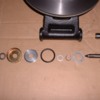
Yep. No way to tell, but I took my time and feel pretty confident that I got everything back together correctly. I was mostly concerned about the inner washer and the locating pin alignment given the previous damage; a couple of the pins were almost completely worn down. Quite a stack of parts to deal with in addition to the weight of the upright assembly...

Attachments

Images (1)
  • Lower_Control_Arm_Install_resize

Add Reply

Post
×
×
×
×
Link copied to your clipboard.
×