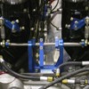
I had my first time out with the Cat last week on the Zandvoord GP cirquit in Holland after a small project running out of control.
Ended up with an all alloy 100KG lighter racing engine. First try was great, No tecknical problems at all. Car was insane fast. But I have one big problem. The engine has a Kinsler velocity stack. The butterfly valves open way to fast. So there is no power control in the turns. It is either no power or to much power.
So I am looking for a throttle linkage that will give a proportional response to the gas pedal. Something like a eccentric wheel.
However there is only very limited space. The engine is real close to the bulkhead. The two shafts with the butterfly valves petrude the velocity stacks just below the window. On the shaft where the linkage arms are mounted is only 1 1/2 inch of space. There has to be a travel stop, a linkage to the other side ( the remaining 4 tacks ) and a control arm or wheel to move the shafts, on this 1 1/2 inch.

So any good ideas how to make a proportional throttle linkage?

Arno
Last edited {1}
Original Post

Replies sorted oldest to newest

If you check my thread "IR injection maintenance" a couple threads down, you can see how mine is set up (not the greatest pic), and others have drawn up a few different combinations.

I've seen another cool setup that had a wheel that mounted in between the stacks, that the cable went to, and the rods that actuated the butterflies came off of the wheel.

This I think could be made to be very progressive.

Here's a link to the thread with the pic of the linkage system I described. it looks very cool too.

http://pantera.infopop.cc/eve/...0045562/m/4121066556
Good thinking Kid,
I was thinking aboud somekind of sliding linkage at the gaspedal. But then again, I saw myself head down under the dash again. Right feet out of the left door, left feet out of the right window. Left arm folded up 3 three times under my body, and only two fingers availlible for work on my right hand. difficult for a lefty. don't we hate that all.....

Mike, it is real hard to make a propportianal linkage just with arms. It is possible though as long as the two shafts rotate the same direction. mine are counterrotating. The wheel in the middle is not so bad idea. Have a look at this.

http://www.gktech.com/index.ph...-throttle-wheel.html
That eccentric wheel looks like it might work well for your needs.

My setup the cable comes from the side, and goes directly to the cross-connecting rod that joins the two halves of the linkages. It is very progressive, but has a long pedal travel.

I'm just running what was on the car when I bought it. The cable was routed such that it melted against the header, so I'm expecting my new replacement wednesday.
photos or a sketch would be nice if you wanted an answer

the eccentric wheel throttle should provide the progressive throttle response. the one thing I would recomend would be to add self alignment to the cable shield support to reduce the cable bending as it enters.

with out knowledge of your setup,it would be hard to provide any detailed suggestions
replacing the throttle arm with an eccentric wheel should do fine for your arrangement.
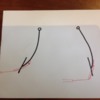
thinking...the eccentric wheel is basicaly a reducing radius arm so why not use multiple arms of varing lenght. I would think just one long arm would give you what you want.

if you can add some info like
total throttle cable travel
butter fly total travel angle
how much reduction of opening in the bottom end
open angle at which to increase opening rate

Attachments

Images (1)
  • throttle_bell_crank
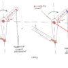
Anytime throttles are actuated with a arm there will be a change of rotational velocity relitive to the angle of the arm.

What this gives you is a lot of throttle shaft rotation for a given pedal movement just off fully closed, then less rotation for a given pedal movement around 1/2 throttle and finally a lot of rotation for a given pedal movement as you approach full throttle.

So you get a variable ratio as you move through the throttle range but in the exactly opposite way that is desirable.

I think that eccentric wheel could be a good remedy for your problem but just a plain concentric wheel may give you the improvement in throttle feel you seek as it will eliminate the varing ratio of the arm you currently are using.
quote:
Originally posted by Aus Ford:
Anytime throttles are actuated with a arm there will be a change of rotational velocity relitive to the angle of the arm...

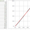
running some numbers in excel, comparing a throttle arm set for +/- 45 degrees with a wheel shows at the begining you get more butterfly opening for less pedal. while the wheel looks like a small advantage in linearity, the great advantage is the reduction of the force resulting in loading on the butterfly bushings. at 45 degrees, the force that results in forcing into the bushings is equal to force being used to rotate.

when I get some more time I hope to add a 2 arm arrangment into excel

Attachments

Images (1)
  • throttle_angle
quote:
Originally posted by Dago:
looking at the front of the engine


That is like the "over-under linkage" from the Kinsler catalogue, and my experience too is that with this setup, it is really hard to get the butterflies from both banks to move perfectly simultaneously...(if not impossible).

I gave up, and changed the connection in between the banks.
Hi Gary Smiler
well actually, the ECU I am using has a exponential function for the throttle. The only thing I need is a " steps ??? " motor. Like the one used on the GM throttle valves. You get a fly by wire gas pedal. considering the problems I had with this ECU before it is not a real option.
beside that, space is really limited. even your R/C setup will be hard to fit in.
Dago,

I should have asked displacement and rpm too but at 2 3/16” it’s less of an issue for the power range you’re likely in. Not sure of your power level but <= 650HP can easily be supported by ~ 2.125” diameter. Many Kinsler systems can be 2.43” and even larger [up to 3”!!). Of course the bore area increases with the square of the diameter and just a little throttle plate rotation can change the open area, and thus air flow, ……a lot. If you want to model the response of your linkage it is better to do so by comparing to the open area in the throttle bore instead of just the angle of the shaft. Of course, the engine behavior you describe could also be induced by cam characteristics too.

I put a lot of effort into the linkage on the systems I built to achieve better drivability. The link earlier in this thread for my “for sale” post provides progressive linkage for better off idle and low speed transition as most of the folks that were buying these systems from me were putting them on street cars. The individual bores were either 50mm or 55mm depending upon desired power level but seem about right for 500-650HP range. These TBs flow significantly more than a 48mm IDA carb because of the absence of the venturi in the center of the throat. Properly sized bores combined with progressive linkage can achieve much finer throttle resolution. Larger than necessary bores are an aggravation to this but often pick up a few peak HP.

The cable and wheel provides a constant amount of rotation for every inch/increment of pedal travel. Cable & Wheel also allows for pulling from any direction so it can be side or forward (or even rearward for front engine cars). The initial position of both the arms on the wheel and the levers on the throttle shafts being driven are initially almost “over center” initially taking much more pedal travel per degree of throttle plate rotation….thus the progression. These systems also had counter-rotating shafts to promote bank to bank symmetry as it mattered whether the high or low side of the throttle plate was inboard or outboard.

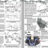
There are many ways to mechanically achieve progressive linkage. You would likely have better results with the “jackshaft” approach shown at the bottom of the Kinsler catalogue page, but if you have very large bores you would likely need a two stage linkage scheme such as suggested in Gary's post or perhaps a scheme such as I used with another cam profile on the cable between pedal and where the cable attaches to the rest of the induction linkage.

Kinsler has been making such systems for a very long time and definitely are very knowledgeable. The initial position recommended by Kinsler for under/over arm and link rod style linkage that mounts on the end of their IR systems is design to minimize the error between the rotation of each bank of cylinders….but it only minimizes error and does not produce the same position of the respective banks throughout their motion to wide open throttle whereas there jackshaft system does.

I always placed the wheel and linkage between the cylinders because it also enabled the use of the Kinsler (or similar) spring screw clamps with arms to connect the throttle shafts. These can provide some individual rotational adjustment for each pair of throttle plates, allow for angular misalignment and thermal growth without binding, and fewer parts overall. Binding is why Kinsler recommends a toe strap. Having one stick WOT when you don’t expect it can wreck or kill you. If not toe-strap, consider a steering wheel mounted kill switch.

Irrespective of where you place and how you configure the linkage, I would strongly recommend you incorporate a throttle stop (wide open) on the accelerator cable or at a location that doesn’t stress the entire linkage system through all throttle shafts. It’s much harder to keep the linkage in tune when it is subjected to a heavy foot and pedal pressure.

Take care,
Kelly
quote:
Originally posted by Panterror:....
I put a lot of effort into the linkage on the systems I built to achieve better drivability. The link earlier in this thread for my “for sale” post provides progressive linkage for better off idle and low speed transition...
Kelly


Kelly, is all of the nonlinear response from the "non equal four bar" arangemnet, or is there something else not shown?
Nice design and execution

Attachments

Images (1)
  • throttle_bell_crank
Well as far as I know it’s just as shown but you have to attach a cable to the drive arm somehow and the initial angle which you pull on the arm can also affect the rate of opening throughout the motion. Most of the over/under geometry linkage schemes that achieves similar results to what I describe for slower initial opening can actually gain the opening rate per inch of pedal/cable travel as you approach WOT which may aggravate Dago’s situation.

I liked the cable driven wheel because angular displacement of the wheel was proportional to pedal/cable travel regardless of what direction you pulled from and it kept the cable tangent to the wheel at all times preventing deflecting and binding on the cable sheath. I positioned the wheel at about the average height of the lever arms driving the throttle shafts so the change in rate through that part of the linkage motion was pretty much negligible. Most OE accelerator pedals produce about 2 ½” more or less of cable travel. You can size the wheel diameter and rest of the linkage from that. When combined with the 50-55mm throttle bore range it just seemed to work well providing a good compromise between top end power levels and resolution…..may be some serendipity too.

This whole affect is similar to sizing throttle plate area on TB of a common plenum intake. Same thing happens when you go to large on the single TB there, just not as extreme. It's more exaggerated in IR because you typically have so much more throttle plate area for a given displacement. It may seem like a lot of theoretical BS but it’s a case of where matching the kinematics of the linkage to the throttle plate open area really does translate to predictable throttle response and better drivability……trying to reduce theory to practice doesn’t always turn out that way but it's sort of satisfying when it's so.

Best,
K
Hi Kelly, That makes all sense.
My engine is out of a V8 Starr racing class from around 2000. It had a common manifold with only one throttle valve. It is a 350Cu revving 8000 RPM. It has a "modest" 550 BHP and 615 NM. However the Torque and BHP curves are really flat. Car is ment for track day's
and just having fun without beeing affraid for the ZF.

As said throttle response is much to aggressive at the lower end. And if you start digging, you will find that this is a common problem with these setup's. I have talked to Kinsler. The progressive setup you see in Figure 3 is more ment for a common manifold, and not for velocity stacks. The total amound of air comming through your trompets will be mixed in the manifold before it enters the cylinders. Looking at it that way, it makes perfect sense.

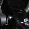
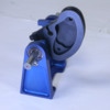
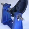
Kinsler has a 600 usd solution though. looks great, but pricy. It will solve the problem completely. it is a evolution of the "jackshaft"

Arno

Attachments

Images (1)
  • kinsler1
Yes, that should work nicely. It is what I was describing when I previously mentioned “use with another cam profile on the cable between pedal and where the cable attaches to the rest of the induction linkage”. It also has mechanical stops I mentioned so you don’t stress the rest of the linkage. You need to give some thought to redundant return springs.

Depending on the cam profile, you should be able to tune that to some degree to suit your engine by varying the initial position/angle of the arms on the jackshaft and the initial position of the cam. Not sure which end of the manifold you intend to mount that on but if in front, it may cause problems with a distributor (if you run one) or the bend angle on the accelerator cable to miss the fire wall. You could put it at the rear but as I said, I prefer the center of the manifold. In the center of the manifold, if one side of the shaft comes loose, you only risk 2 barrels at WOT, not a whole bank or all. However, not sure there is room in the center on the Kinsler manifold.

Kinsler parts are not cheap, but isn't meant to be. Good linkage is money well spent, especially on an IR system.

Best,
K

Add Reply

Post
×
×
×
×
Link copied to your clipboard.
×