quote:
Originally posted by Rocky:
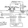
I found that for an ignition system wired per George's diagram, green strain relief modules do not work, even though the connectors will mate.
I have two green modules that I got, and when I plugged in my the green boxes, the ignition did not fire.
There is an extra wire in the green strain relief boxes that was not in my Blue units. I suspect that this "no connect" is the cause. I tried grounding both boxes externally, and they still didn't work.
When I return from vacationing, I'll try and describe the wiring differences better.
Sig - obviously your system is wired correctly for the green boxes, since yours runs. It would be interesting, and slightly helpful to the community if you can tell us where the extra wire goes!
To answer your questions ...
1973 through 1974; Motorcraft ignition module #DY-157; black strain relief
Ford’s Breakerless ignition showed up in 460 V8 equipped North American Lincoln vehicles in 1973. In 1974 the breakerless ignition was employed in more applications, including all 6 cylinder and V8 models sold in California and all 400 V8 and 460 V8 applications in the 49 states. The first ignitions were not called Duraspark; they were referred to simply as breakerless ignitions. I am not certain when the “Duraspark” name tag began showing up on the ignition modules. The coil had 1.50Ω primary resistance, 10,000Ω secondary resistance and 1.35Ω ballast resistance; this is identical to the coil and ballast resistance employed for the breaker-point style ignitions. Spark plug gaps were increased from 0.035” to 0.044”. The ignition module had 7 wires terminating in two connectors, one with 4 pins, and one with 3 pins.
The wiring of the 1973/1974 ignition module connectors is as follows:
4 pin connector:
Red – provides battery voltage to the module when the ignition switch is in the run position
White – provides battery voltage to the module when the ignition switch is in the start position
Orange – connects to the magnetic sensor in the distributor
Purple – connects to the magnetic sensor in the distributor
3 pin connector:
Green – carries the ignition coil’s “primary” current to the ignition module
Black – carries the ignition coil’s “primary” current from the ignition module to a ground connection in the distributor
Blue – connects to the “BATT” terminal of the coil and serves as an overload shunt; i.e. it was intended to bleed-off any pulses of excessive voltage which may occur in the module.
1975; Motorcraft ignition module #DY-166; green strain relief
The breakerless ignition became standard equipment in all North American Ford/Lincoln/Mercury models in 1975. There were 6 revisions made to the ignition that year:
1 – A new coil was introduced (Motorcraft #DG-314) having 1.17Ω primary resistance, 8,500Ω secondary resistance, and 1.30Ω ballast resistance. This increased the coil’s primary current, and raised the coil’s secondary output voltage.
2 – Internal module components were “beefed-up” to handle the greater primary current.
3 – New “blue” material was used for the distributor cap to better insulate the increased secondary output voltage.
4 – Ignition module 3 pin connector “key tabs” were re-oriented and the connector wiring was revised to prevent the use of 1975 modules in 1973/1974 systems.
5 – A new “horse shoe shaped” coil connector was introduced to prevent reversal of the coil wiring.
6 – Silicone insulation was introduced to the ignition wiring to handle increased temperatures in the engine compartment.
The wiring of the 1975 ignition module connectors is as follows:
4 pin connector:
Orange – connects to the magnetic sensor in the distributor
Green – carries the ignition coil’s “primary” current to the ignition module
Black – carries the ignition coil’s “primary” current from the ignition module to a ground connection in the distributor
Purple – connects to the magnetic sensor in the distributor
3 pin connector:
Red – provides battery voltage to the module when the ignition switch is in the run position
White – provides battery voltage to the module when the ignition switch is in the start position
Blue – connects to the “BATT” terminal of the coil and serves as an overload shunt; i.e. it was intended to bleed-off any pulses of excessive voltage which may occur in the module.
1976 through 1986; Motorcraft ignition module #DY-184; blue strain relief
There were 3 revisions made to the breakerless ignition in 1976:
1 – Internal improvements were made to the ignition module making the blue “overload shunt” wire unnecessary; therefore the blue wire was eliminated. Thus the number of module wires was reduced to 6 wires.
2 – The 3 pin connector was replaced by a 2 pin connector, to reflect the elimination of the blue wire.
3 – The orientation of the purple and black wires in the 4 pin connector was reversed.
1977
Revisions to the standard breakerless ignition were again made in 1977. Ballast resistance was lowered to 1.10Ω. The ignition module and coil were carried over from 1976, with some internal upgrading to handle increased primary current. This upgrading did not affect how the system operated however. This was the year the larger diameter caps were first fitted to the distributors, and ignition wire diameter was increased from 7mm to 8mm to improve insulation. Spark plug gaps increased to 0.050". The name Duraspark II was applied to the ignition system. 1977 modules can be installed in 1976 vehicles, the connector key tabs and connector wiring remained the same.
A high output ignition was introduced in 1977, named Duraspark I. That ignition was not an upgrade of the earlier ignition, it was an entirely new ignition utilizing a high output coil (Motorcraft #DG-316) having 0.70Ω primary resistance, 7,750Ω secondary resistance and no ballast resistance (the coil operated at full battery voltage). A new ignition module employing dynamic dwell (Motorcraft #DY-204) was utilized to properly charge the coil. That ignition module had a red wiring strain relief. Spark plugs were gapped at 0.060". The ignition was designed to ignite leaner mixtures, diluted by increased amounts of exhaust gas, thus reducing misfires and improving the emissions performance of California vehicles (California’s emissions regulations were stricter than the national regulations). This module’s 4 pin connector “key tab” was re-oriented and the orientation of the orange and green wires in the 4 pin connector was reversed. This was done to prevent using the Duraspark II module in a Duraspark I equipped vehicle.


