351 CLEVELAND BASICS AND PERFORMANCE TUNING
FOR HIGH PERFORMANCE-STREET CARS AND SPORTS CARS
During the 1960s Ford had manufactured small high winding V8 performance engines that demanded a lot from the driver and were some of the most expensive engines Ford manufactured. Although such engines provided spirited performance in lighter vehicles such as the Shelby Cobra and the 1965 Mustang, they were not as well suited for powering heavier vehicles. Ford had also manufactured large V8 performance engines that overwhelmed the chassis and tires of its production cars with low rpm torque and made it all too easy for the driver to lose control. The large engines were also detrimental to a vehicle’s handling due to the amount of weight they added to the front of the vehicle. After those two extremes Ford settled on manufacturing a mid-size V8 with a heavy dose of mid-range power. And just like in the story of Goldilocks and the Three Bears, that was just right. ![]()
The 351C proved THERE IS A REPLACEMENT FOR DISPLACEMENT!
Link: The Sound of a Charging Rhino
Link: A Charging Rhino at Lake Nagambie
Link: A Charging Rhino at Bathurst
Link: A Charging Rhino at Spa-Francorchamps
Link: A Charging Rhino Revving to 7K on an Australian Back Road
CONTENTS
BECOMING FAMILIAR WITH THE 351C
Part 1: Terminology and Production Information
Part 2: Durability
Part 3: State of Tune
TUNING THE 351C
Part 4: The Combustion Process (thermal efficiency)
Part 5: Induction System (volumetric efficiency)
Part 6: Exhaust System
Part 7: Camshaft and Valve Train
RACING WITH 351C POWER
Part 8: Preparing A 351C Racing Engine
OTHER 351C RELATED TOPICS
→ NEW 2022 Link: Making the 351C Super Stock
Link: The 351C lubrication system
Link: Rebuild - Freshen Up - Overhaul
Link: Unleashing the Performance Capabilities of Cobra Jet (Q Code) Engines
Link: 275/285 Custom Street Cam
Link: Ignition Upgrade - Ford EDIS (Distributorless)
Link: 500 or More Horsepower From Small Block Fords
Link: 408 Cubic Inches Using All Ford Parts
PART 1 - TERMINOLOGY AND PRODUCTION INFORMATION
For those of you new to the 351C or those who have questions about the terminology, a quick overview. The 351C is a member of the engine series Ford named the "335 Series". There are 3 pairings of engines in this series.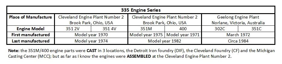
In Ford terminology a 351C equipped with a 4 barrel carburetor was referred to as a 351-4V; 4V did not mean 4 valves as it does today, rather it meant the carburetor had 4 venturis. For the same reason a 351C equipped with a 2 barrel carburetor was referred to as a 351-2V. The US manufactured 351-4V was the focal point of the engine series in terms of high performance, it was installed in Ford and Mercury automobiles in the USA and Canada, it was exported to Australia and installed in Australian Ford Falcons and Fairlanes, and it was installed in several sports cars manufactured in Italy and one sports car manufactured in Australia.
The 351-4V was manufactured in 3 versions we refer to using Ford's engine codes for those engines; i.e. the M-code engine (351 4V), the Q-code engine (351 4V GT or 351 4V CJ, i.e the 351 Cobra Jet version), and the R-code engine (351 4V HO, i.e. the 351 Boss version). The 2 barrel carburetor version is referred to as the H-code engine for the same reason. All 3 versions of the 351-4V were tuned for higher rpm with cylinder heads having raised intake ports of larger cross section than the heads found on the 351-2V. Those heads were known as 4V heads because they were designed for engines equipped with four barrel carburetors. The 4V heads were also initially equipped with larger 2.19" intake valves and 1.71" exhaust valves (1970 - 1972). The cylinder heads installed on 351-2V engines were referred to as 2V heads, they were equipped with 2.04” intake valves and 1.65” exhaust valves.
Link: 351C US Production History
PART 2 - DURABILITY
351C SHORT BLOCK DURABILITY
Outside of the R code engines ('71 351 Boss & '72 351 HO) all US manufactured 351 Cleveland short blocks were basically identical with three exceptions: (1) H code & M code engine blocks had two bolt main bearing caps, Q code engine blocks had 4 bolt main bearing caps; (2) the 1970 through 1972 pistons were flat top pistons with 3 cc dome volume, the 1973 and 1974 pistons were dished pistons with 8 cc dome volume; (3) the Q code engines had a bit larger/heavier crankshaft dampers. The nominal deck clearance for ALL H code, M code, and Q code engines was 0.035 inch.
The US blocks were all cast from the same type of iron, they had the same thin cylinder walls (nominal 0.160") and they had the same bulkhead thickness. The main bearing caps were all equally robust, the only difference being some were cast for two bolts, others were cast for 4 bolts. Naturally aspirated 351 Clevelands have never required aftermarket steel main bearing caps, splayed bolts, etc. The main bearing caps secured by 2 bolts resisted "walking" until about 8000 rpm! Therefore 4 bolt main bearing caps were not needed for a street-performance engine, a sports car engine, or any engine limited to about 7000 rpm. The measures mechanics take to stabilize the main bearing caps of a small block Ford have never been necessary for a 351 Cleveland. The production block was admired for the sturdiness of its bottom end and it was notorious for its thin cylinder walls and its lubrication system issues.
All 351 Cleveland crankshaft castings were also identical, they were all cast from the same high nodularity iron alloy, they were all externally balanced, and they were all equally strong. The crankshaft was partially counter-weighted (having 6 counter-weights) as opposed to being fully counter-weighted (having 8 counter-weights). This type of crankshaft is common for mass-produced crankshafts because it is less expensive and less difficult to manufacture and results in a lighter crankshaft. It was also designed to maximize bob-weight as opposed to being designed to minimize bearing load. This is common for cast iron crankshafts because cast iron is less dense than steel, therefore cast iron crankshafts usually require external balancing. The goal in maximizing the crankshaft's bob-weight is to minimize the amount of external weight required to balance the crankshaft. There were no drawbacks to this type of crankshaft at the engine speeds for which the engines were designed, but all such crankshafts heavily "load" the second and fourth main bearings and bulkheads during high rpm operation (>7500 rpm). This didn't stop people from using the crankshaft for racing however! The cranks would be internally balanced with "mallory metal" and then used for 8,500 rpm NASCAR racing and 10,000 rpm Pro-Stock and Super-Stock drag racing. They were pretty tough crankshafts. Unfortunately the blocks took a beating at constant ultra-high rpm usage, the production blocks would eventually develop cracks at the second or fourth main bearing saddles that would extend upward through the bulkheads and crack the walls of the adjacent cylinders. This is not a concern for street performance or sports car engines however.
We've established the cranks are ALL tough iron alloy castings. They are externally balanced and should be internally balanced for racing. They are partially counter-weighted which means they should be restricted to about 7200 rpm usage. There are two other considerations. The first is the oil passages drilled within the crankshaft. The oil passages are suspected to contribute to the Cleveland's lubrication woes. There is no other way to explain why the connecting rod bearings for cylinders 2 and 7 always fail the first or the worst. And finally, cast iron has dampening properties which steel lacks. Consequently the cast iron crankshaft is "gentler" on the cylinder block than a steel crank. The factory iron crankshaft maximizes the durability of the thin wall cylinder block.
All 351 Cleveland connecting rods were identical forgings, they were all forged utilizing the same heat treated 1041 steel. The factory rod nuts were a source of trouble, they had a reputation for stripping their threads at high rpm. The factory connecting rods were strong enough however for sustained 7200 rpm racing once they had been properly shot-peened and equipped with 180,000 psi rod bolts; but only the connecting rods found in the R code engines were prepared this way by the factory.
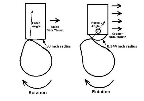
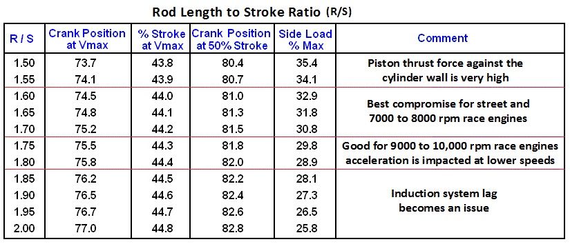
Ford testing in the 1960’s found a rod length to stroke length ratio of 1.72:1 provides the ideal rod length for an engine operating up to about 7500 rpm. It reduces cylinder wall thrust as much as possible while being just short enough to avoid the onset of induction system lag. The 351W has a rod length to stroke length ratio of 1.70:1. However, the 351C has a rod length to stroke length ratio of only 1.65:1. The 351C connecting rod (5.780 inches length) was intentionally shortened a bit to improve "street" (low rpm) performance.
Connecting rod length also impacts the distance the piston is pulled out of the bore at BDC. The piston of a stock 351C is pulled so far out of the bore at BDC that the wrist pin is partially exposed (0.126 inch) beyond the lower edge of the bore. This is not ideal, but has never been an issue with street engines. 6.00 inch long Chevy connecting rods were once considered de rigueur when preparing a 351C for racing however. The rod length to stroke length ratio with Chevy rods was 1.71:1 and the wrist pin remained 0.087 inch above the lower edge of the bore at BDC.
It is best if the piston is never pulled out of the bore so far as to expose the wrist pin because the axis of piston rocking is the wrist pin axis. The further the piston is pulled out of the bore, the less surface the piston skirt has to press against. The piston skirt can’t perform as intended if it has no cylinder wall to press against. Thus the further the piston is pulled out of the bore at BDC the more it shall rock within the bore. Piston stress and wear will increase. At some point operating friction begins to increase. At a further point visible piston damage will begin to occur. By that point connecting rods can begin to bend or twist as well.
The R code engines ('71 351 Boss & '72 351 HO) were also equipped with standard production castings & forgings which received special inspection. The crankshafts were brinnel tested to insure a certain degree of hardness, and the connecting rods were magna-fluxed to insure there were no flaws in the forgings.
The 1971 Boss blocks were equipped with four bolt main bearing caps but were otherwise no different than the other production blocks. Four bolt main bearing caps became a standard production option the following year (Q code & R code engines). The connecting rods were shot-peened and equipped with 180,000 psi chromoly rod bolts;
The R code engines were equipped with lighter - stronger forged pistons with rounded skirts whereas all other 351 Cleveland short blocks were equipped with cast pistons. The H.O. engines also had crankshaft dampers which were bonded and heavy enough for engine speeds above 6000 rpm whereas all other 351 Cleveland engines had unbonded, lightweight or medium-weight crankshaft dampers.
Since ALL of the short blocks are all identical in strength it is possible to build an equally durable 351C performance engine no matter which short block you have on hand as a foundation. Round skirt pistons resolve the cylinder wall cracking issue; tappet bore bushings and fully grooved main bearings correct the deficiencies of the lubrication system. The crankshaft is more than durable enough for street applications, and stress cracks at the second or fourth main bearing saddles are not an issue for engines operated at or below 7200 rpm. The factory connecting rods employing pressed wrist pins and equipped with ARP rod nuts (or the complete ARP bolt & nut kit) are plenty strong for a street engine and an occasional blast to 7200 rpm.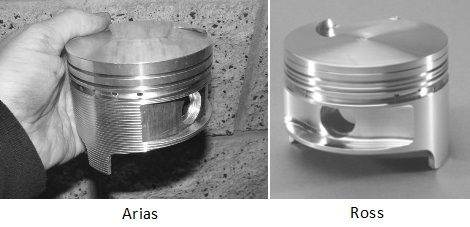
IMPROVING DURABILITY
When we spend time and money improving the performance of an engine, it is a natural assumption that we are doing so because we plan to take advantage of that increase in performance from time to time. We plan to test the limits of the car's chassis and stress the engine to a greater degree. None of us want the engine to fail while we are "flogging" it. So there are a small number of 351C problem areas to set straight as a precautionary measure, thereby insuring the things that go terribly wrong from time to time don’t happen to your car’s engine. The durability of other parts should be improved to insure the engine can sustain higher output, insure it can sustain operating at higher rpm, and insure it can endure high performance driving (i.e. being flogged) without damage.
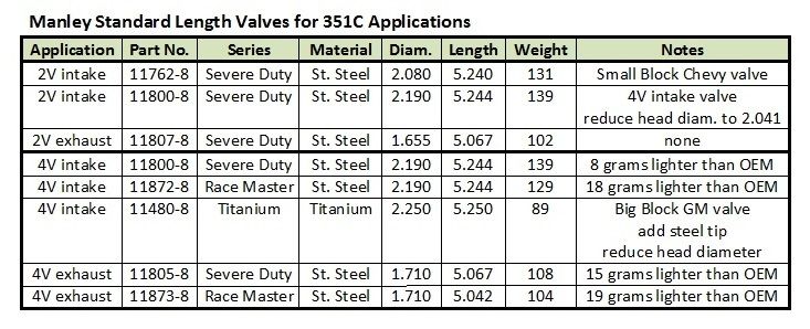
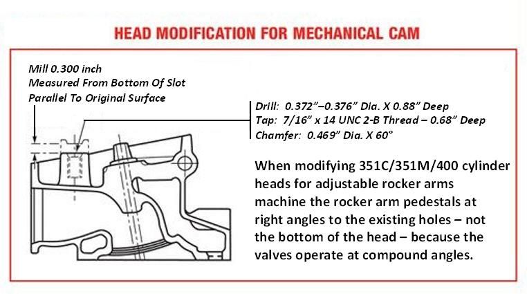
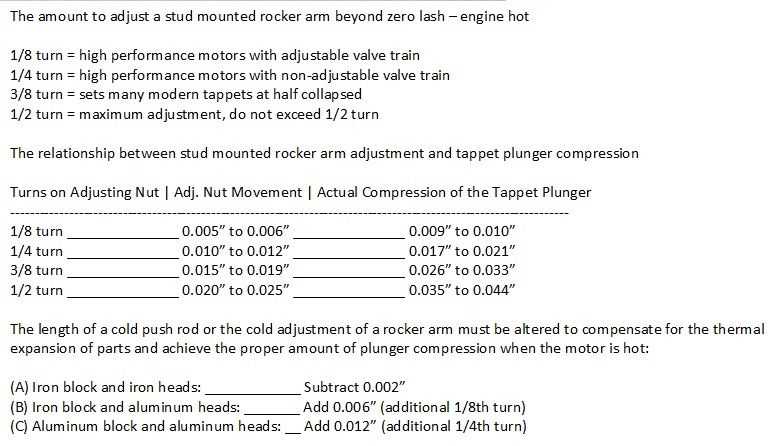
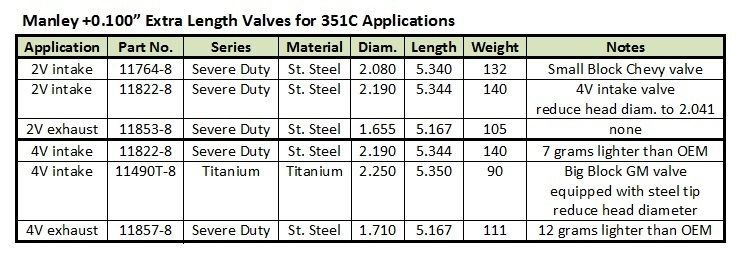
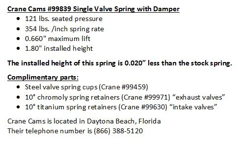
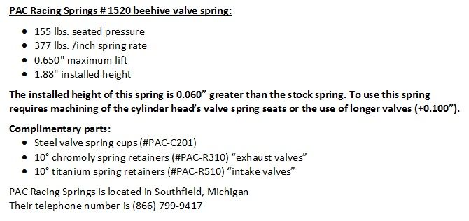
(detailed information regarding Manley valves, valve springs, push rods and rocker arm bolts is provided further below in PART 7)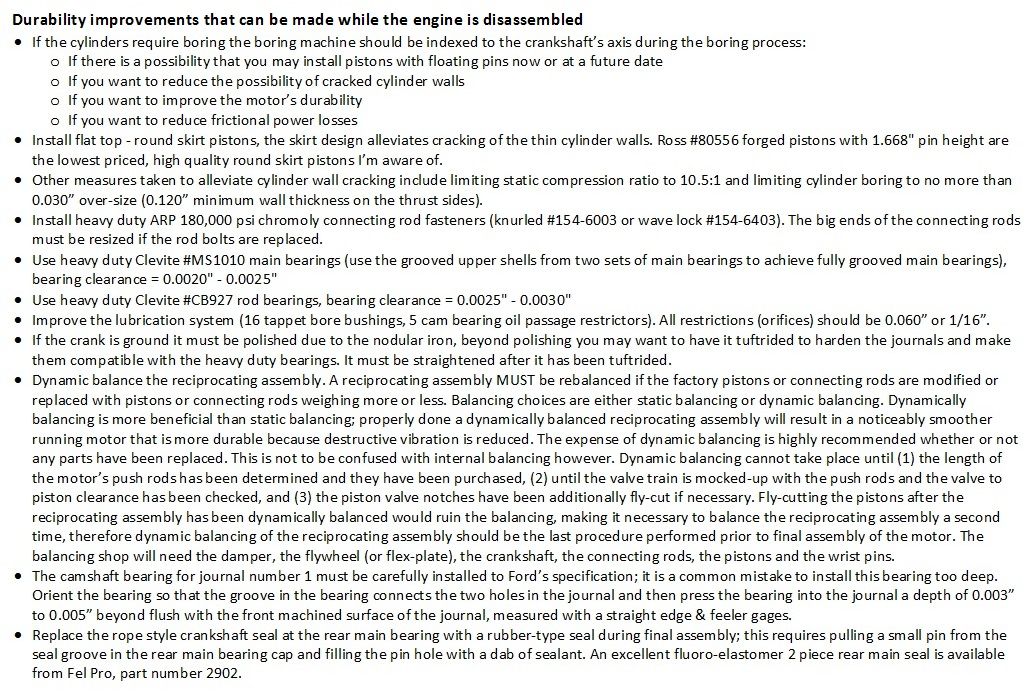
LUBRICATION SYSTEM
Every way in which the 351C design deviated from the design of the SBF was to make an improvement, with one exception ... the lubrication system. The SBF utilized three lubrication passages; oil was supplied to the crankshaft main bearings first via a dedicated passage, then at the rear of the block the oil supply was split into two additional passages to supply the two banks of tappets; this is referred to as a main priority system. To save money the 351C was designed with only two lubrication passages, one for each bank of tappets. Lubrication for the crankshaft’s 3 central main bearings was supplied by branches intersecting the same oil passage shared by the right hand bank of tappets.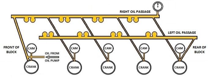
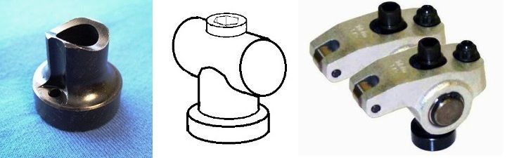
Ford found it necessary to redesign the tappets installed in the 351C due to the large port in the wall of each tappet bore, a result of the way in which the tappet bores intersect the oil passages. Tappets designed for the SBF and 351W allowed too much oil to flow to the 351C valve train. When a 351C equipped with the "wrong" tappets is operated at higher rpm the rocker covers flood with oil while the oil pan is slowly pumped dry at the same time. Thus the 351C has compatibility issues with tappets having certain types of oil metering designs; this also illustrates the importance of limiting the amount of oil flowing to the 351C valve train.
Lubrication system pressure is supposed to be controlled by a relief valve built into the 351C oil pump. The setting of the relief valve is controlled by a spring intended by the designers to maintain 60 psi nominal hot oil pressure (50 psi minimum and 70 psi maximum) but the 351C has a propensity for low oil pressure. Hot oil pressure below 50 psi indicates an excessive amount of oil is flowing into various "leaks and clearances”, overtaxing the capacity of the oil pump. The 351C also has a propensity for bearing wear. The symptoms of insufficient lubrication are evident even in low mileage engines; those symptoms include ribbons of bearing material lying in the bottom of the oil pan, scoring on the bearings, bearings being polished, or bearings worn so much they are no longer silver in color but copper colored. Obviously the excessive amount of oil flowing into various "leaks and clearances" is not flowing to the rod bearings!
The two basic design flaws of the lubrication system are:
(1) There's no control of where the oil is flowing nor is there control of how much oil is flowing.
- Main bearing lubrication does not have priority or first claim to the oil discharged from the oil pump
- An excessive amount of oil flowing to waste in the tappet clearances reduces the amount of oil available for lubricating the crankshaft
- An excessive amount of oil flowing to the valve train or the camshaft bearings also reduces the amount of oil available for lubricating the crankshaft
(2) The large ports in the walls of the tappet bores create three additional problems.
- The ports allows too much oil to flow to waste
- The ports create tappet compatibility issues, possibly allowing too much oil to flow to the valve train
- The ports allow cavitation resulting from the motion of the tappets to spread within the oil passages.
People are under the assumption 351C lubrication problems occur predominantly above 7000 rpm, but cavitation does not turn off and on like a light switch at a specific engine speed. Cavitation increases gradually, becoming more severe as the speed of the tappets increases; cavitation is therefore impacting the oil passages to a lesser degree at engine speeds below 7000 rpm. Cavitation simply increases to the point of causing rod bearing failure at some point beyond 7000 rpm. But any amount of cavitation in the right hand oil passage shall impede the flow of oil to the crankshaft's 3 center main bearings to some degree.
There are those who insist the lubrication system is "good enough" up to 6000 rpm. Yet even low-mileage engines equipped with factory camshafts were plagued by low oil pressure and worn bearings. High lift rate camshafts and typical high mileage tappet bore wear worsen the problems. The lubrication system’s performance also worsens as engine speed increases; the performance diminishes to the point of rod bearing failure at some point beyond 7000 rpm. The bearings for connecting rods #2 through #7 are affected, but the bearings for connecting rod #2 or connecting rod #7 are usually the first to fail. All of the lubrication system problems impact solid tappet motors and hydraulic tappet motors equally. The symptoms are the same regardless if the rev limit is 5000 rpm, 6000 rpm, 7000 rpm or higher; the symptoms merely worsen as rpm increases. The consensus has always been that any 351C being rebuilt for any kind of performance application (from mild to wild) needs some improvement to the lubrication system.
Improvements to the 351C lubrication system should focus upon correcting the design flaws rather than the symptoms. One corrective action would be to modify the lubrication system to better control where oil is flowing and to better control how much oil is flowing. We can both minimize the excessive amount of oil flowing to waste via the tappet clearances and limit the amount of oil flowing to the valve train by installing 16 tappet bore bushings. We can also limit the amount of oil flowing to the camshaft bearings by installing 5 cam bearing oil passage restrictors. If we allow oil to flow unrestricted to the crankshaft after making those modifications we are essentially giving lubrication of the crankshaft priority, i.e. we've succeeded in modifying the 351C lubrication system to behave as a main priority system. Thus modified there is plenty of oil volume even with the standard volume oil pump, the standard oil pump spring shall operate in the middle of its range and control oil pressure at about 60 psi in the manner it was originally intended to do, and the quantity of motor oil flowing to the crankshaft shall be substantially increased at all engine speeds, even low rpm!
The tappet bore bushings also correct the other design flaw; they eliminate the large ports in the walls of the tappet bores, metering oil to the tappets via small orifices instead. This isolates the oil passages from the motion of the tappets thus eliminating cavitation in the oil passages; this is another vital step in making it possible for oil to flow unimpeded to the central 3 main bearings. The tappet bore bushings also resolve tappet compatibility issues.
The reasonably priced do-it-yourself tappet bore bushing installation kit available from Wydendorf Machine (selling for $400 USD) makes all of this affordable and within the budgets of a large range of engine projects. Wydendorf Machine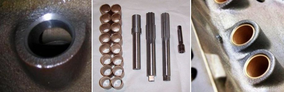
Four decades ago only eight bushings were installed in the right hand tappet bores, but it is customary these days to install bushings in all sixteen tappet bores. The reasons for this are to insure consistent oil control at all sixteen valves, to perform optimally with hydraulic tappets, and to resolve 351C tappet compatibility issues. The tappet bore bushings remove the task of oil metering from the tappets or push rods, and they make the 351C more tolerant of which type of tappet is installed.
My preference is to drill the bushings with 0.060" (or 1/16") orifices for all hydraulic tappet applications, all street and sports car applications, and all road racing and endurance racing applications because once the bushings are pressed into the block the orifice size can't be changed. The 0.060" orifices are a good size for a general purpose or "do-it-all" type of engine set-up.
Four decades ago four restrictors were installed in the passages supplying oil to cam bearings #2 through #5, but it is customary these days to install restrictors in all five cam bearing oil passages. Experience has proven an oil passage restrictor for cam bearing #1 improves the performance of the lubrication system, therefore it is assumed the oil passage for cam bearing #1 diverts a significant amount of oil from the main oil passage which it intersects. Acquiring five camshaft bearing restrictors shall require purchasing two Moroso #22050 restrictor kits, because each kit only has four cam bearing restrictors. The restrictor for cam bearing #1 is installed in a different manner than the restrictors for the other four cam bearings; it must be installed more deeply within the cam bearing oil passage so that it restricts oil to the #1 cam bearing and not to the #1 main bearing. The large restrictors included in the Moroso kits are not used.
PART 3 - STATE OF TUNE
THE MYTHS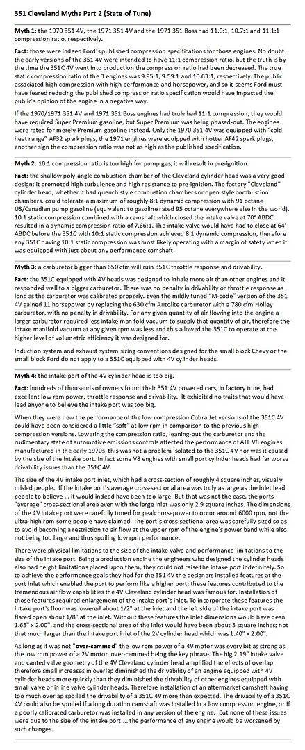
THE BASELINE
The 4V version of the 351C was not a low performance engine requiring a bunch of aftermarket parts to turn it into a hot performer; it was equipped with high port, big valve cylinder heads which were tuned for peak horsepower at 6000 rpm. It had outstanding thermal efficiency by virtue of the high turbulence combustion chambers. It was also equipped with a 750 cfm carburetor and a high lift camshaft (in all but the M code version). It was obviously intended to be a high performance engine off the showroom floor. The engine's performance can be described as having good drivability, a strong dose of mid-range power, and the willingness to rev to high rpm. This is an ideal power characteristic for a high performance street car, a sports car, or a GT car. Over the decades I've read reports praising the engines in high end sports & GT cars such as Ferrari, Lamborghini, Mercedes and Aston Martin for having similar power characteristics. This characteristic of the 351C 4V is something I try to avoid diminishing in any aspect when I tune the engine for higher output.
Unfortunately the 351C was manufactured in an era when air pollution standards out-paced automotive pollution control technology, therefore the engine's performance suffered. Ford never manufactured the 351C in a version that realized the engine’s full potential. Ford published a "guide" for hot-rodding the 351C in 1970 (Autolite publication #MP-1046) which I realized by about 1975 was not so much a guide for hot-rodding the engine as it was a guide for de-smogging the engine. The guide did not recommend any special high performance parts, the recommendations centered around production parts. The obvious reason for this, the 351C with 4V cylinder heads was a high performance engine off the show room floor. I consider de-smogging the engine the same as optimizing it to perform in the manner Ford originally intended. Ford rated the output of a 351C modified according to their guidelines, equipped with the GT/Cobra Jet hydraulic tappet camshaft, at 65 horsepower above the 1970 factory 351 4V specification. That's 365 horsepower at the flywheel, or 290 horsepower to the rear wheels! So you see, there's quite a bit of performance built-into the factory engine. Thus equipped the engine operated on premium pump gas, i.e. gasoline rated 91 octane in the US and Canada or rated 95 octane everywhere else. The engine idled well, it had good manifold vacuum and it retained the drivability typical of a factory engine. In fact drivability improved. Even those owners who are opposed to “hot-rodding” the engine in their car would enjoy the improvement in low rpm pep and drivability that can be achieved by simply reversing the smog-tuning of their car’s engine in this way. Ford's 365 horsepower version of the 351C is the baseline for experiencing the performance the 351C truly offers. A 351C in this state of tune may prove to be more than enough for a great number of drivers. Here's a summary of that guide for those of you who are curious.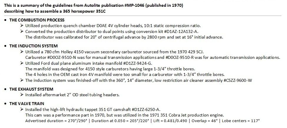
I'd like to make two observations:
(1) the 1971 351 Cobra Jet engine, rated at 280 horsepower, had a specification similar to this except it was equipped with open chamber D1ZE 4V cylinder heads, 8.7:1 compression ratio, a 750 cfm Autolite 4300D carburetor and cast iron exhaust manifolds. 85 horsepower was lost in the process!
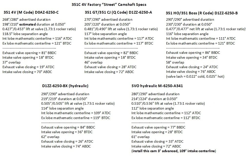
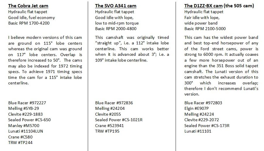
(2) Two parts not mentioned in the guide, but available in 1970, were the D1ZZ-6250-BX hydraulic tappet camshaft and the Shelby intake manifold. The camshaft specs were:
290°/290° advertised duration
219°/219° duration at 0.050"
0.505"/0.505" valve lift
62° overlap
114° lobe separation angle
It would have added 16 horsepower to this combination, stretching the output to 381 horsepower. The Shelby manifold would have added another 20 horsepower. Combined those parts would have raised the potential output of this combination to 401 horsepower. That was a lot of horsepower in 1970, especially from an engine of this displacement. It could be achieved without ultra-high compression, without super-premium gasoline, without a solid tappet camshaft, without dual four barrel carburetors AND without diminishing the engine's drivability.
COMPARING THE CYLINDER HEADS
A comparison of the differences in the state of tune of the 351 2V and the 351 4V boils down to a comparison between the differences in performance and power characteristic imparted by the cylinder heads.
One aspect of cylinder heads that impacts the performance of an engine is their combustion chamber. The combustion chamber volume affects the engine’s compression ratio, and the combustion chamber’s design affects the maximum compression ratio that can be utilized for any given gasoline octane without detonation or pinging. The combustion chamber design also affects the engines thermal efficiency and therefore its horsepower output. The 351C 2V cylinder head and 4V cylinder head share the same poly-angle wedge combustion chamber design, and therefore they share the same excellent thermal efficiency. However, as one would expect, with differences in valve sizes, port heights and port cross-sections the cylinder heads differ in volumetric efficiency. The maximum air flow performance of an unported 2V intake port is about 200 cfm at 0.400” intake valve lift; equivalent to approximately 400 horsepower. The maximum air flow performance of a fully ported 2V intake port is about 250 cfm at 0.500” valve lift. That’s not bad performance, that much air flow is equivalent to approximately 500 horsepower; which is more than enough horsepower for any vehicle equipped with street tires.
In absolute terms the 4V cylinder head is a better cylinder head for high performance because it has higher volumetric efficiency. The air flow performance of an un-ported 4V intake port is 245 cfm at 0.500” valve lift, but the air flow continues to increase as the valve opens further … 275 cfm at 0.600” valve lift, and 290 cfm at 0.700” valve lift. A motor equipped with unported 4V cylinder heads and a “street cam” opening the intake valves 0.600” off their seats has the potential of producing 550 horsepower! After porting the air flow performance further improves ... 290 cfm at 0.500” valve lift, 325 cfm at 0.600” valve lift, and 350 cfm at 0.700” valve lift. That much air flow is equivalent to approximately 700 horsepower.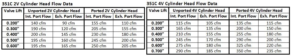
There are two practical differences between motors equipped with 2V heads and motors equipped with 4V heads one must consider in deciding which type of cylinder head to use; (1) differences in power characteristic between the two motors and (2) differences in gearing required by the two motors. The average cross-sectional area of the 2V intake port is a bit smaller than the average cross-sectional area of the 4V intake port, thus the 2V intake port is tuned for a power band about 1000 rpm lower than the power band of a motor equipped with 4V cylinder heads. Some street performance and sports car enthusiasts prefer the low rpm biased power characteristic of the smaller cross-section 2V ports. The mid-range rush of an engine employing 2V cylinder heads is not as pronounced as an engine with 4V heads therefore the power characteristic of a 2V motor seems somewhat more sedate. Those who prefer the power characteristic of a motor with 2V heads feel it is more "refined" while the 4V motor is "brutish". A motor with 2V heads also lacks the endless high rpm pull of a motor with 4V heads. The 2V cylinder heads are better choices for low rpm torque applications such as towing and hauling vehicles, off-road and rock crawling vehicles and heavy vehicles in general.
The Cleveland 4V cylinder head design was chosen by Ford because of its suitability for endurance racing, it provides an unprecedented wide and flat torque curve and a power band characterized by a strong mid-range rush. Power at lower rpm with the 4V cylinder head is peppy, smooth and linear. As long as it is not "over-cammed" the low rpm power of a 4V motor is every bit as strong as the low rpm power of a 2V motor. A 4V motor can "light-up" the rear tires at low rpm with little effort. A 4V motor builds "steam" with engine speed and then hits a strong mid-range rush which is like the afterburners of a jet engine kicking-in! From that point on a 4V motor pulls harder and harder as the engine speed climbs (as long as the carburetor is big enough). I call the 4V motor's power characteristic the "Charging Rhino". Although I personally do not have a desire for a motor producing more horsepower than what can be achieved with the 2V cylinder heads, I prefer the power characteristic of a motor equipped with 4V cylinder heads.
Due to this difference in power characteristic 4V motors require lower gearing to operate the motor better within its power band which is at generally higher engine speeds. Since 2V motors do not require as low gearing as 4V motors they will potentially cruise at a more comfortable (lower) engine speed and return better fuel economy. Newer 5 and 6 speed manual transmissions and 4 speed automatic transmissions can provide both low gearing for acceleration and high gearing for cruising and fuel economy; the 4V motor is at less of a disadvantage in regards to "cruise" engine speed and fuel economy when used in conjunction with 4 speed automatic transmissions and 5 or 6 speed manual transmissions. Conversely, in that regard the 2V motor is at more of an advantage with 2 or 3 speed automatic transmissions and 3 or 4 speed manual transmissions.
In summary, as they came from the factory both versions of the 351C had good low rpm power, good throttle response, and good drivability. The 351C 4V power band/torque curve was wider, with performance to about 6000 rpm. The volumetric efficiency of the 2V cylinder head is excellent, and the 4V cylinder head has tremendous capabilities in that regard. With ratings of 250 horsepower (351C 2V) and 300 horsepower (351C 4V) the volumetric efficiency of both versions of the 351C was under-utilized. Higher engine speeds and higher outputs are attainable with relatively minor modification of the engines’ induction and exhaust systems.
A PRIME EXAMPLE
There is a forum member whose Pantera motor makes over 400 bhp at 6000 rpm on a chassis dyno; i.e. over 500 bhp at the crank. The engine is equipped with the standard stroke factory crankshaft. The iron 4V heads are ported, the compression ratio is set at 10:1, the induction is individual runner with fuel injection, the exhaust is a bundle of snakes type exhaust. The camshaft is a relatively mild hydraulic roller cam, the Crane HR216 camshaft. The cam specs are:
278°/286° advertised duration
216°/224° duration at 0.050"
0.562"/0.586" valve lift
58° overlap
112° lobe separation angle
The camshaft's specs are rather modest by today's standards. This is actually a very mildly tuned engine with good drivability, yet the power output is tremendous. Since the cylinder heads were designed to make peak horsepower at 6000 rpm the engine didn't need a long duration camshaft to make high rpm power. A lot of money was invested in the induction and exhaust systems, and that investment paid-off. The volumetric efficiency of the iron 4V heads is very high with IR induction, and the bundle of snakes exhaust helps too. This exemplifies the advantages of a good induction and exhaust system and it exemplifies the capabilities of the 4V cylinder heads. It also exemplifies the concept of improving the engine's performance without diminishing the power characteristic in any aspect. The "state of tune" was increased by improving the induction system, not by using a "big" camshaft. The design of the 4V cylinder heads gives us this option.
This naturally aspirated 500+ horsepower 351C (5.75 liter) makes as much horsepower as Chevrolet's naturally aspirated 7 liter LS7 Corvette engine, which is touted by Chevrolet as being a show case of high technology. The LS7 is 35 years newer, it uses 11:1 compression, CNC ported heads, a higher lift hydraulic roller camshaft and induction via a modern long runner fuel injection intake manifold.
The output of this 500+ horsepower naturally aspirated 351C is less than 50 horsepower lower than the output of the engine in the Ford GT. Like the LS7, the engine in the Ford GT is 35 years newer than the 351C. It displaces 5.4 liters, it is equipped with 32 valve dual overhead cam cylinder heads, high lift camshafts, and induction via a supercharger putting out 12 psi of boost!
Unlike either of these engines, the 351C was mass produced as inexpensively as Ford was capable, and it was manufactured from lowly cast iron. Yet if you bolt on a modern high-lift low-overlap camshaft (112° to 114° lobe centers, 50° to 60° overlap) and good induction and exhaust systems it can still keep up with these highly touted engines, and it can do so while maintaining its wonderful power characteristic. I consider 500 horsepower a high state of tune for a 351C, but it doesn't need to run like a drag-race engine to achieve high output ... unless of course you want it to.
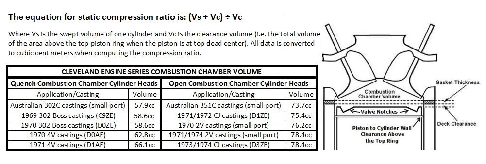
PART 4 - THE COMBUSTION PROCESS (thermal efficiency)
The aspect which most significantly contributes toward the power producing capabilities of any engine is the combustion process. The combustion process is therefore the logical place to begin when optimizing an engine or tuning it for higher output. The parts which influence the combustion process include the design of the combustion chamber, the design of the piston dome, the compression ratio, the seal of the piston rings against the cylinder wall, the seal of the valves on the valve seats, the cylinder to cylinder consistency of the fuel air mixture, the quality of the fuel air mixture (better fuel atomization), the cylinder to cylinder consistency of the ignition system and the quality of the spark produced by the ignition system.
The shallow poly-angle combustion chamber of the Cleveland cylinder head is a very good design. It is the most important aspect of the head and the single biggest contributor towards the power producing capabilities of the Cleveland engine, yet people seldom think twice about it. The biggest improvement aftermarket cylinder heads offer over the factory cylinder heads is their “high swirl” combustion chambers.
COMPRESSION RATIO IMPROVEMENT
If the 351C in your car is a low compression version (having open combustion chamber cylinder heads and less than a TRUE 9.5:1 "static" compression ratio) then the single most important step to take towards improving its performance shall be to raise the engine’s compression ratio. Raising the compression ratio of any low compression 351C to operate on 91 octane (US/Canadian) pump gasoline (nominal 10:1 static compression ratio) shall increase the engine’s output by about 20 horsepower and improve the engine’s responsiveness. Although this does not sound like a lot of horsepower the amount of snap added to the engine’s performance gives the impression that the horsepower has increased much more than it actually has. It is not possible to set-up an engine having low compression to provide the type of performance most people are looking for. You are not giving the standard displacement 351C equipped with 4V cylinder heads a fair opportunity to show you the performance it is capable of having if you don’t raise the compression ratio.
The compression ratio of an engine is limited by the octane of the gasoline that shall be used. There are two rating systems for octane being used around the world, many people are unaware of the differences and unaware that low octane "regular" fuel in Europe is high octane "premium" fuel in the US and Canada. Since this is an international forum, its important that we are all on the same page, the information below should help.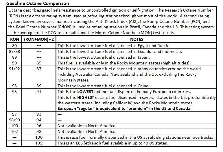
Although we usually refer to compression ratio in terms of the “static” specification, it’s the “dynamic” compression ratio that more accurately describes an engine’s operating compression ratio, and therefore more accurately describes the limitation in the amount of compression a motor can tolerate. The “dynamic” compression ratio takes into account the piston’s “dwell” time at bottom dead center and how many degrees after bottom dead center (ABDC) the intake valve closes. My preference is to set-up an engine to operate on 91 octane US/Canadian pump gasoline (equivalent to gasoline rated 95 octane everywhere else in the world) since higher grade 93 or 94 octane fuel is not universally available throughout North America. The factory “Cleveland” cylinder heads, whether they have quench style combustion chambers or open style combustion chambers, can tolerate a maximum of roughly 8:1 dynamic compression with 91 octane US/Canadian pump gasoline. The aftermarket cylinder heads which are cast in aluminum and equipped with high-swirl combustion chambers are capable of tolerating at least 8.4:1 dynamic compression ratio burning the same pump gas. My preference is to set the dynamic compression of a street engine a little lower than the maximum amount in order to give the engine a margin of safety. 10:1 static compression combined with a camshaft which closes the intake valve at 70° ABDC results in a dynamic compression ratio of 7.66:1. That’s a reasonable margin of safety for the factory (iron) heads. For your comparison, the factory 351 Cleveland engines with the highest static compression ratios, i.e. the 1971 BOSS 351 and the 1970 351 4V, had dynamic compression ratios of 7.69:1 and 7.62:1 respectively.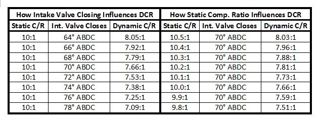
Following are seven common scenarios for raising the compression ratio of the 351C.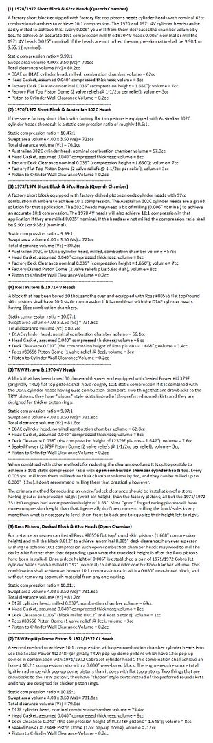
A Word of Caution: Decking the block, milling the heads, installing pistons with greater compression height, or installing pup-up dome pistons increases the importance of checking piston to valve clearance during assembly of the motor, especially with high lift or long duration camshafts. Pop-up dome pistons will normally require more total ignition advance too.
PISTON RINGS
Piston rings are a subject of rapid technological development fueled by the auto manufacturer’s pursuit of better fuel economy and lower emissions. It’s an area that you should spend some time researching and getting advice before you make a purchase. Piston ring thickness and tension creates friction that resists crankshaft rotation. Decreasing piston ring thickness or tension reduces the energy required to keep the crankshaft rotating, and therefore increases the power available at the rear wheels. The additional cost of high-tech rings over the price of standard cast iron rings constitutes one of the least expensive ways to increase horsepower. Modern thinner or lower tension piston ring sets can offer higher output at the rear wheels and better durability with no penalty in the life of the rings. A good quality OEM thickness 5/64” plasma moly ring set using a barrel faced ductile iron top ring will cost about $100 to $120. A top-of-the-line "thin" 1/16” chromium nitride faced ring set using a steel top ring will cost $280 to $380. So improving the technology of the piston rings will cost $280 or less. That's some relatively inexpensive horsepower. The Ross pistons I recommend are designed for the thinner 1/16" rings.
IGNITION SYSTEM IMPROVEMENT
If the 351C in your car is equipped with a breaker point ignition, or even an old and tired breakerless ignition then it must be improved. A smooth and precise operating "high output" breakerless ignition system is just as essential to a high performance engine as raising the compression ratio. There are many ignition systems to choose from. One possible ignition system choice that employs Ford parts is a Ford Duraspark distributor calibrated for 20° of centrifugal advance in by 3000 rpm, triggering a Duraspark I module and a Duraspark I coil.
California was the only state in which Ford vehicles were equipped with Duraspark I ignitions; Ford enthusiasts outside of California were not aware of the existence of this ignition and had no experience with its performance, which was a shame. The Duraspark I ignition was also known within Ford as the "high output ignition", it was much more than a different Duraspark module, it was considered an entirely different ignition system than the Duraspark II ignition system. It was Ford's first high output ignition system, and Ford's first ignition system to employ "dynamic dwell". The Duraspark I ignition was utilized in all California V8 equipped applications in 1977, and limited to California 302 V8 applications in 1978 and 1979. The Duraspark I ignition module is identified by its RED wiring sealing block.
At the heart of the Duraspark I ignition was a special ignition coil having a very low primary winding resistance. The coil was also operated with no ballast resistance; therefore current flow in the primary windings was substantially increased in comparison to the primary current of Ford's standard (Duraspark II) ignition system coil. The core of the Duraspark I coil was designed to accept a much higher magnetic charge from the increased current flowing in the primary windings, thus producing a substantially higher voltage to the spark plugs. The higher magnetic charge also allowed the coil to reach "full charge" more rapidly than Ford's Duraspark II ignition system coil. Spark intensity was greatly increased ... especially at higher rpm. If this coil's primary winding had been charged with the conventional "fixed-dwell" control utilized by the Duraspark II electronic ignition system it would have overcharged at low rpm and overheated. Therefore an ignition module with a unique primary current control circuit was required to compliment this coil.
Differing from the various Duraspark II ignition modules, the Duraspark I module didn't control charging of the coil in the conventional way. The Duraspark I module utilized dynamic dwell, meaning the module constantly adjusted dwell based on current flow in the coil's primary circuit, independent of engine speed. This prevented over charging or under charging the coil throughout the motor’s rpm range. Dwell therefore varied with respect to the degrees of crankshaft rotation but remained relatively constant with respect to actual coil charging time; and the coil was properly charged throughout the engine's operating range.
The Duraspark I ignition produced the most consistent and most potent spark of any Ford ignition. This was Ford’s best ignition for igniting lean mixtures or rich mixtures, which was the purpose for its existence. The ignition ignited mixtures the Duraspark II ignitions could not. The dynamic dwell feature gave this module good high rpm performance too as the coil was charged properly (never under-charged or over-charged) from idle to 7000 rpm. This ignition’s design was more elaborate than the design of the Duraspark II ignition, and therefore it was more costly for Ford to manufacture (replacement Duraspark I modules cost several times the price of replacement Duraspark II modules).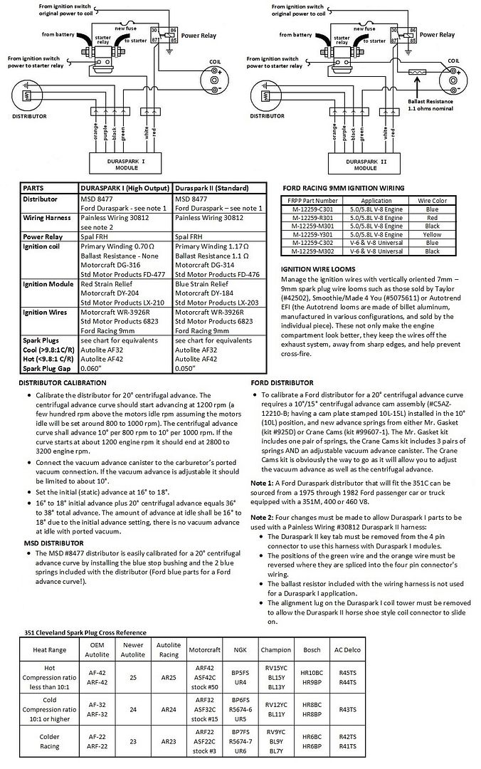
continued in the next post