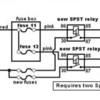
I've been having problems with my radiator fans lately so I pulled apart the relays and they are both toast. On one, the spring plate has rusted enough that it no longer has any spring tension. On the other, the points are burned completely off.

Careful cleaning and setting has them both working again, but not for long. Is there a commonly available replacement for these relays, or do I have to hunt down the exact same units?

Thanks, Mooso.
Original Post

Replies sorted oldest to newest

If you cant find an exact replacement easily in the Auto shops there try an industrial electrical wholesaler.

Relays are relays be it for industrial control systems or cars - just make sure the coil is 12VDC and the relay contacts are rated accordingly - I think 20Amps, but happy to be corrected there if someone knows exactly.

You may need to work out some other mounting arrangement for it though.
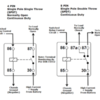
I think you'll be looking for the 'Bosch' automotive style mini relay. Pins 85 & 86 are the pilot circuit, 30 & 87 are the load side. They tend to look the same but there are some variants.
1. Most have two pin 87, these are both normally open contacts.
2. Some have a pin 87 & 87a, 87a is normally closed, 87 is normally open.
3. Some have integral diodes that suppress internal arcing (more $).
...I went with the 'Bosch' Style, comes with a 'Plug-In' Wiring Harness.
But, I was sure to buy the Relays with the 30 Amp Rating Contacts!
You can find them everywhere, and on Ebay, they're common.

The Originals were Junk! The Coil wire was 'Hair Thin'! and they Burned-Out Easily.
...I was Installing a Custom 'Bank' of relays adjacent to the Clutch Master Cyl. In fact, 6 are mounted on a Plate, Bolted to the Grounding Stud, that Grounds ALL. The Relays handle the Main Fans, Aux. Fans, Headlights, Driving Lights, Other and a Couple of Spares.

The point was to get rid of the Old Wiring!
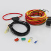
Spal (the cooling fan manufacturing company) sells a relay harness. A small DIN style relay is housed within a plastic or rubber enclosure which is dust and water-proof, is tab mounting similar to the oem relays, and includes lots of long heavy gage wiring and a fuse holder. The part number is "FRH" (fan relay harness).

I've seen them in the Summit Racing catalog, on eBay and on Amazon. The sell for about $30 to $35. Picture below.

Attachments

Images (1)
  • frh
Great info !!

I have two new 12V 70A relays laying around but am unsure how to connect them. I'm guessing that 87 goes to the fan, 30 goes to the temperature switch, and either 85 or 86 goes to 12v in. Do both 85 and 86 go to 12v in, or is one a ground, or is no ground needed?

It looks like these relays are going to be good enough if I can just get the wiring right.

Thanks everyone.
Looks like my guesses on the connections were mostly wrong.

Just to clarify, it looks like 30 and 86 are jumpered across and both receive 12V in. In this application, the switch is the ignition switch and the temp switch is not considered a switch at all, but is considered a ground lift that is either connected or disconnected.

If I have this right, I'll connect these relays up this weekend and see if it all works.

Thanks, Mooso.
Correct Mooso, basically.

In that illustration, your ignition switch determines whether there is 12vdc to the fans. But it's only when the thermostat closes that the ground is made, which then closes the relay thus completing the fan motor circuit and making the fan run.

This probably protects the ignition switch contacts somewhat. However, this still leaves the full amps running through the ignition switch, I believe, and if the engine is hot (thermostats closed) then the power gets switched by the ignition switch contacts.

As an alternative (instead of jumping 30 to 86), by supplying a fused hot line from the battery to 30 (NOT through the ignition switch), only the turn-on voltage for the relay goes through the ignition switch. The main power to the fans would bypass the ignition switch this way, but things would still function the same.
From sticky #2 of the engine forum

(1) Removes the load of the fans from the ignition switch
(2) Prevents engine run-on, you can throw away the diodes
(3) Controls both fans with one temp switch. Therefore if the temp switch is selected to complement the thermostat, and the cooling system is in good condition, the fans should turn off and on automatically as needed; like a normal car.

Attachments

Images (1)
  • FanCircuitRevised_zps2d19b1de
I have been working on a "Hot Box" to go along with the inertia based auto cancel turn signal and light controller I make. The set up has the headlight relay, the bright relay and 2 additional supplemental relays with an extra 3-5amp tap for radio and fuel injection memory.

The circuit is not ready for prime time yet. I have gotten the circuit where the supplemental relays can support about 20 amps continuous but a sustained 30 amps still has too much heat rise. There is a lot of added copper in a circuit to make it do work at these amps.

One thing I learned is that a 30amp circuit breakers get hotter then I realized and that I am comfortable with when a sustained 30 amp load is put on it. Intermentant loads are no problem.

I am looking at restructuring what I am doing to use 75 am solid state relays to find a comfortable level at a sustained 30 amps.

There are also a few fans out right now which have two circuits for high and low and they use 2 relays; one for each circuit. If you put 2 relays on a single circuit and one relay does not engage then you overload the other.

The light circuit and the relay circuit is my entire electrical circuit on my home built buggy:


Add Reply

Post
×
×
×
×
Link copied to your clipboard.
×