Quick question:
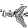
When assembling the rear axles with new bearings, there is a shaped washer under the split axle nut.
This washer has a taper on one side and is flat on the other side. The taper, to me, appears that it would face downwards to compensate for any casting irregularities in the head of the splined yoke. This would let the split nut sit against a perfectly flat face when tensioning to the required 400ft/lbs.
But........my washers may have been previously fitted upside down as there are marks on them where they have come into contact by the split nut.
Can anyone verify which way this washer should actually be seated?
OzGT5 (Guest)
Yes and no. Number 17 is the offending culprit. There is a certain way that it has to go.
OzGT5 (Guest)
All those 9's are interesting also. I presume that they are bearing dust seals and with sealed bearings those numbers become irrelevant.
OzGT5 (Guest)
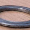
Okay, a picture tells a thousand words.
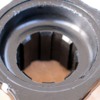
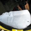
Here's the flat side of washer No. 17.
Here's the flat side of washer No. 17.
Attachments
OzGT5 (Guest)
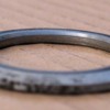
And here's the tapered side:
Attachments
OzGT5 (Guest)
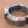
Now here's the split nut. The raised section of the split nut is nearly exactly the same as the flat section on the tapered side of the washer indicating that these may fit together.
Attachments
OzGT5 (Guest)
But........
Here's the flange. Hard to see but the flange isn't dead flat inside as the casting shape starts to curve slightly. This initially indicated to me to put the washer in with the tapered side down so when it pulls up tight, the tapered part of the washer stays clear of the casting rounded shape.
Then the fully flat face of the washer must contact the split nut, and if that is the case, then why have the slightly raised section on the split nut?
Attachments
Robert,
My original ones were install with the taper facing the nut. That raised part on the nut is referred to as "semi-finished". Definition: "SEMIFINISHED is machined on the bearing face to provide a straight, flat surface for the washer".
John
My original ones were install with the taper facing the nut. That raised part on the nut is referred to as "semi-finished". Definition: "SEMIFINISHED is machined on the bearing face to provide a straight, flat surface for the washer".
John
OzGT5 (Guest)
Thanks John, so maybe the washer is also 'semi finished' and has that same raised section to specifically come into contact with the base of the nut?
quote:then why have the slightly raised section on the split nut?
I've checked all my manuals, and the online sites. Nothing shows this in detail.
But, as you noted, it appears the taper side of the washer should go in first so it stays clear of the rounded shape of the flange.
As for the ridge on the nut, you wouldn't want the full face of the nut pressing on the outer edge of the washer, as the washer radius and the flange rounded shape radius are likely not an exact match. With just the raised edge of the nut contacting the washer, the nut's force is all directed squarely on the bearing area of the washer.
Does that make sense?
Hope I helped.
Larry
Robert,
The washer is most likely "parallel ground" so that the top and bottom faces are parallel to each other. This distributes the nut's force evenly.
John
The washer is most likely "parallel ground" so that the top and bottom faces are parallel to each other. This distributes the nut's force evenly.
John
OzGT5 (Guest)
Well the plot certainly thickens. Larry thinks as I do, yet John is oposite, thinking that the two ground surfaces on the nut and washer should meet.
It's certainly an interesting one and I'm supried that it hasn't surfaced before. There are a lot of owners who have either changed axles or bearings or both and evryone must come across this sae issue.
I could just put mine back together the way it came apart, but I'm not convinced it was correct to start with.
Logic says that the job of that nut is to pull the flange down onto the bearing at 400+ ft/lbs.
If I sit the washer into the flange it's near on impossible to see if there is clearance to the tapered section of the casting.
If john is right and the raised section of the washer is parallel ground, then it would make sense to do as Larry says and put the washer taper down and tighten the raised section of the split nut down onto the flat side of the washer.
As you can see, my washers are marked pretty badly. Had they been assembled as suggested in the above paragraph, I would only se rotational scoring on the inner 3mm of the washer face and this would give me a good clue.
I have located a 3/4 drive torsion wrench so will try and do this job over the weekend, so if anyone can definatively solve this puzzle in the next day or so it would be most helpful.
Maybe anyone close to CA could give Bob at Precision Pro-Formance a call. I'm sure he could anwer it, especially given that he makes the axles and split nuts.
Robert,
I'll call Bob (when he gets in) and let you know what he says.
In my earlier post, I stated what I found upon removal of my original axles. They could have been assembled incorrectly by the factory.
John
I'll call Bob (when he gets in) and let you know what he says.
In my earlier post, I stated what I found upon removal of my original axles. They could have been assembled incorrectly by the factory.
John
When we took two different cars apart (71 and 74) and the cupped side/relived side was toward the outside of the car. We assembled it the same way and have had no problems. I think it was designed that way to give a little extra clearance with the splines on the axle and yoke. You will notice that as you slide the yoke on the axel the splines are pretty close to the top of the yoke spines. If the spacer between the bearings has much wear the yoke can stop on the axel splines before the spacer is held tightly between the bearings. This also moves the full force of the compression away from the splined area on the yoke.
Not sure how well I explained this but hope you can follow the attempt.
Mike
Not sure how well I explained this but hope you can follow the attempt.
Mike
quote:Larry thinks as I do, yet John is opposite, thinking that the two ground surfaces on the nut and washer should meet.
I'm not sure John is in disagreement with us.
He merely stated the two sides are parallel, implying that the torque applied to one side is evenly applied to the other.
Which is what we want to happen.
I think as long as the torque is being properly applied, then it becomes an issue of fitment.
And the tapered side of the washer would seem to want to be placed towards the tapered side of the casting.
I've got a call into Bob and he is supposed to call me back.
I'll update when I hear from him.
Larry
I just tried calling Bob, but he won't be back for an hour or so, and Don was busy with a customer.
I called Wilkinson's and talked with Bill. He said that the taper goes TOWARD the nut, as I had found mine to be installed from the factory.
I will call Bob later to get his answer.
John
I called Wilkinson's and talked with Bill. He said that the taper goes TOWARD the nut, as I had found mine to be installed from the factory.
I will call Bob later to get his answer.
John
I agree with Mike's logic. If the taper were installed toward the yoke (toward the outside of the car), then the smaller diameter seating surface of the washer's tapered side would put the compression force very close to the splines of the yoke.
Inversely, if the taper were installed toward the nut (toward the inside of the car), then the compression force would be farther from the splines of the yoke.
Interesting discussion.
John
Inversely, if the taper were installed toward the nut (toward the inside of the car), then the compression force would be farther from the splines of the yoke.
Interesting discussion.
John
I just spoke with Bob, and he said that the taper goes TOWARD the nut....small end of washer at the nut, large end of washer at the yoke.
Looks like two for two for the taper at the nut.
Anybody want to call another vendor for a third opinion??
John
Looks like two for two for the taper at the nut.
Anybody want to call another vendor for a third opinion??
John
OzGT5 (Guest)
Thanks guys, that's conclusive enough for me, and also logical based on my original thoughts.
Excellent work everyone.
Excellent work everyone.
Bravo!
Mike
Mike
OzGT5 (Guest)
Hi guys, I'm working away under my car and just thinking about putting all of the rear suspension back together, and I note that the cover for the petrol tank, like a forward inner guard liner is missing. So basically my left rear wheel is throwing rocks at the petrol tank.
I need to fabricate a new section, but can anyone post images of what it should look like, with particular reference to the ponts of attachment to the body.
I need to fabricate a new section, but can anyone post images of what it should look like, with particular reference to the ponts of attachment to the body.
I don't have pics but you are welcome to come and have a look.
I am 10 minutes from Dandenong.
regards
Paul
I am 10 minutes from Dandenong.
regards
Paul
OzGT5 (Guest)
Paul, is your car off the road at present?
I have to come down to Carrum Friday so could swing by. Email me your numbers: rhayden@panteraaustralia.com
I have to come down to Carrum Friday so could swing by. Email me your numbers: rhayden@panteraaustralia.com
OzGT5 (Guest)
Well I managed to get down to Paul's place and have a look at the cover forward of the drivers rear wheel.
Appears to be a totally different shape to the other side of the car and much more complex shape than I expected.
Pauls car has big 20's on the rear and it was a bit hard to see in there.
Does anyone have their car off the road that can take a picture of the petrol tank guard forward of the LHS rear wheel?
Robert,
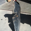
I currently happen to have my inner fenders out of my car. Here are a couple of pics of the fuel tank side. If you need more photos, higher resolution photos, or some measurements let me know. Best of luck.
In this first picture the side facing up faces the tire.
I currently happen to have my inner fenders out of my car. Here are a couple of pics of the fuel tank side. If you need more photos, higher resolution photos, or some measurements let me know. Best of luck.
In this first picture the side facing up faces the tire.
Attachments
OzGT5 (Guest)
You're a legend. Much more complex than I thought.
SHame there isn't an easy way to trace around it so I have the cuttout shape, and then I could just try to replicate the bends once cut out of flat steel.
Why do you blokes have to live on the other side of the World?
SHame there isn't an easy way to trace around it so I have the cuttout shape, and then I could just try to replicate the bends once cut out of flat steel.
Why do you blokes have to live on the other side of the World?
Robert,
If you want, I could trace it on a large piece of paper, fold it up, and stuff it in an envelope. I don't think it would cost that much to send it through the mail. However, I have no idea how long it would take it to get to you. Let me know.
If you want, I could trace it on a large piece of paper, fold it up, and stuff it in an envelope. I don't think it would cost that much to send it through the mail. However, I have no idea how long it would take it to get to you. Let me know.
OzGT5 (Guest)
Generally only 5 - 7 days through normal postal chanels.
That really would be great, but you would need tp slip off that rubber edge, and if there is a chance of damaging that edge it may be a bother.
Things get pretty hard and brittle.
That really would be great, but you would need tp slip off that rubber edge, and if there is a chance of damaging that edge it may be a bother.
Things get pretty hard and brittle.
How about just tracing it on a Graph paper then e-mail a hi-res photo. The outline does not need to be perfect as the rubber makes-up the gaps, I used a seal from pick-up cab cover.
4NHOTROD did his in stainless steel sheets
Denis
4NHOTROD did his in stainless steel sheets
Denis
Denis - funny you should mention that.
I have a buddy that is an IT guy with access to a document scanner that can copy the exact size of very large items. We are going to see if we can scan my tracing and then email the JPEG to Robert.
If that doesn’t work I’ll see if I can round up a large sheet of graph paper. Thanks for the idea.
I have a buddy that is an IT guy with access to a document scanner that can copy the exact size of very large items. We are going to see if we can scan my tracing and then email the JPEG to Robert.
If that doesn’t work I’ll see if I can round up a large sheet of graph paper. Thanks for the idea.
OzGT5 (Guest)
There are some great blokes on this site. Devin went to a lot of trouble to trace his gaurd liner, then have it scanned and sent to me on a large format file. I had it printed and mounted to card at a local copy shop, and here it is now situated inside my rear fender.
Attachments
OzGT5 (Guest)
It's not a perfect fit, as I think my quarters have been pumped a bit even before the flares went on, but it's a great starting point.
I went out today and got a couple of sheets of 0.8mm zinc coated steel (2 in case I bugger up the first one) and this weekend I'll have a go at fabricating this missing part of my car.
Many thanks to Devin for this great job.
I went out today and got a couple of sheets of 0.8mm zinc coated steel (2 in case I bugger up the first one) and this weekend I'll have a go at fabricating this missing part of my car.
Many thanks to Devin for this great job.
OzGT5 (Guest)
Thanks to Devin I now have an inner liner. I cut it up yesterday and fitted it today. The part is now in the car with the first coat of paint on it.
Garvino,
Can I get a copy of that inner fender shield large format file?
Thanks!
Garth
Can I get a copy of that inner fender shield large format file?
Thanks!
Garth
Garth,
I sent a copy of the JPEG to your website’s contact email. If you need anything else or need it emailed somewhere else let me know.
If anyone else needs a copy of the tracing please PM me your email address and I will forward it to you as soon as I can.
Thanks.
I sent a copy of the JPEG to your website’s contact email. If you need anything else or need it emailed somewhere else let me know.
If anyone else needs a copy of the tracing please PM me your email address and I will forward it to you as soon as I can.
Thanks.
OzGT5 (Guest)
Today I fitted the new inner rear fender liner, complete with pinch mould. Fully coated in a tar based underbody sealer which I've used elsewhere under the car.
Here's a few pictures. Was certainly great to actually start fitting up the renewed suspension after a few months off the road.
Here's a few pictures. Was certainly great to actually start fitting up the renewed suspension after a few months off the road.
Attachments
OzGT5 (Guest)
And the pinch mould section:


