quote:
Originally posted by OzGT5:
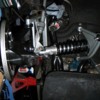
The factory clearance from head of wheel stud to those countersunk head screws and the bearing retainer must be miniscule?

You would like to see 3 or 4mm here to allow some clearances but this seems not to be the case.

I thought the caliper mounting tabs were close to the rotor surface, but the stud head clearance is crazy.


The clearance between the heads and the upright is very close, but when my stock bearings failed the first thing I noticed was the rotor rubbing on the caliper mounts.

Mike
Robert,
Have you checked to make sure the rotor is tight to the axle flange? A portion of the knurled stud is a press fit into the axle flange and will tend to keep the rotor away from the axle flange if not pressed in tightly. I use thick washers that are larger than the stud knurls and use lug nuts to hold the two pieces together after pressing the studs through the axle. The dust shield was used with the original factory bearings that did not have seals but most of them have been discarded when sealed bearings were installed. You have sealed bearings so these are not required. They are just a thin piece of sheet metal.
Yes, there is zero clearance between he axle head and the rotor as I pressed this on and held it with nuts and washers exactly as you suggested.

I got up early and went down to the shed to annoy the neighbours with the lathe.

I mounted each stud and whisked 0.5mm off each head and then also linished the top of the bearing retainer plate and took it down level with the top of the screw heads.

It's now assembled and went together perfectly. So far I've pulled up 350 ft/lbs and it turns easily, just like the LHS.

Now I need the next size tension wrench and she can go back together.

A pic from this morning.

Attachments

Images (1)
  • 0437
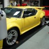
Was a good day in Melbourne today.

The big cat is back on all four paws again for the first time in many months.

Everything went together well, and now just waiting on the clutch slave and master which are out to be re-sleeved.

Couple of small cosmetic and eelectrical jobs to do whilst I'm waiting for that, but by the end of the week I should drive it again.

Attachments

Images (1)
  • 0445
quote:
Originally posted by OzGT5:
Yes, there is zero clearance between he axle head and the rotor as I pressed this on and held it with nuts and washers exactly as you suggested.

I got up early and went down to the shed to annoy the neighbours with the lathe.

I mounted each stud and whisked 0.5mm off each head and then also linished the top of the bearing retainer plate and took it down level with the top of the screw heads.

It's now assembled and went together perfectly. So far I've pulled up 350 ft/lbs and it turns easily, just like the LHS.

Now I need the next size tension wrench and she can go back together.

A pic from this morning.


That’s one way to make the problem go away! Do you have any ideas on the root cause? Seems like it must be bad machining on the axel or the bearing width.

Mike
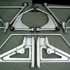
Robert, the car looks awesome! I noted you have different upper rear a-arms? Where did you get them? Are they a tad longer to allow for lowering the car and eliminating camber problems?

Also, what did you paint you a-arms with. I bead blasted mine and am almost ready to paint them and have been debating what paint to use, paint with a hardener, without or just go with the spray can paint like Rustoleum Industrial grade which I've had pretty good luck with on other parts I've painted.
Mike, I checked and double checked the bearings and they were fine. All I can figure is that the wheel mounting face of the axle or the rotor step must have been slightly wrong.

A tip to others going down this road. I really wanted billet axles made or proper USA steel so went to Precision Proformance. The axles look beautiful but I obviously found some issues with the final ground shaft size not being perfectly parallel, and now it appears that the heaad of the axle might not be perfect also.

With precision fit components like this it's imperative that you check and double check your measurements and not buy 'off the shelf' witht he expectation that they are just going to fit and be perfect. I'm lucky to have the facilities at home to spin a few though off, but most blokes won't have a machine shop set up in their garage.

Tom - I used a polyurethane wheel paint for the control arms. It's a VHT product from USA and is a nice metalic silver. Being a wheel paint it has some resistance to stone chips apparently. I'm yet to make up my mind about this as it marked easily putting it all back together.

I reckon if you have the arms completely pulled down, including the ball joints, then powder coating is by far the best treatment. As I didn't have the ball joints out, I chose the painted option. I'll report in on the durability as time goes on.

The rear uppers I presumed were stock as they were already on the car. I'll check back through my paperwork and see if they are mentioned.
quote:
Originally posted by Tom@Seal Beach:
I'll check on the Polyurethane paint. Never thought about wheel paint, but that sound like a great option.

Maybe your car got a different a-arm...I have a narrow body. The tubes on my a-arm terminate before they get to the ball joint. There is a steel plate that the ball joint is mounted to and the tubes are welded to that. I'll check it again.


Should look like this http://www.panteraplace.com/Te...0rebuild%20d%209.jpg

Mike
I compared your photo to a spare upper rear stock a-arms I have and they are a match.

Tom, maybe you have modified a-arms? Did you ever get around to any mods of your own as we had contact on?

FWIW I had all my a-arms powder coated.

I don't see the upper front A-arms in your photo and cannot recall if you said you had sent them to be modified for the additioanl caster? If not you really should do so as a wide body Pantera is a literal white knuckle ride with stock caster.

You may also find benefit ina laregr rar sway bar factory GT5's came with a 7/8" bar. I have 1" on mine and like it.

Julian
Robert, I'm so glad you posted your suspension arm pictures. I have been looking into either buying new upper a-arms to lengthen them to increase the camber adjustment, or modify the ones I had. I assumed mine were the stock arms. But now realize that the bushings on those arms are the only poly bushings on the car. The rest are rubber, so I'm assuming they are a vendor modified arm.
It will look better in a few more days once the clutch cylinders are back in it and it gets back on the road.

A few more things to fix between then and now though:

- Passenger window doesn't work.
- Drivers window slow.
- Leaikng windscreen seal.
- Front wheel aliginment.
- Sort out the throttle cable/linkage which is too heavy.
- Put the new rubber/felt trim around the drivers door.

Then just need to wait a bit longer till Kirk sends my new short bumpers and I can remove the USA shark nose.

I see a light at the end of the tunnel........
Mike Dailey suggests that the following are the factory settings:

Front Settings

Camber, 1/8 degrees neg to 1/8 degrees pos.
Caster, 2-3/4 degrees pos.
Toe-in, 1/8"

Back Settings

Camber, 3/8 degrees neg to 5/8 degrees neg
Toe-in 1/8" to 3/16"

His car was aligned and the finished specifications were:

Front Settings

Camber, Left 0.5 degrees, Right 0.5 degrees.
Caster, Left 1.8 degrees, Right 1.4 degrees.
Toe-in total, 0.12"

Back Settings

Camber, Left -0.6 degrees, Right -0.6 degrees
Toe-in total, 0.21"

My car uses 11" and 13" wheels and the fronts have a 32mm spacer to fill the guards properly as the wheel offset appears to be wrong. It also has Johnny Woods castor mod to the upper front arms.

Normally these vehicle mods would require a variation to 'standard' wheel alignment specs.

Your thoughts Gentlemen?
Yes they do.

One other thing that is sometimes over looked is how the overall stance of the car impacts the caster. They seem to handle better at speed with a slight nose down stance, but any nose down subtracts from the desirable caster. So a slight nose down stance is better for the caster than a bunch of nose down. The other thing to consider about the overall stance is that the top of the door (below the window frame) is not parallel with the bottom of the pitch weld. It angles up toward the front of the car, so the car will look like it is running up hill if the pinch weld is parallel to the ground. From my measurements and calculations a 1” difference between the front and back pinch weld equals 1 degree. Mine is a tad over 3/8” lower in front or .375+ degrees nose down. That stance puts the top of the door just very slightly lower in the front in relation to the ground. A lot to think about, but it is amazing how getting the car to sit with a good stance and ride height makes such a huge difference in its appearance and handling.


Mike
Another fun day!!

Clutch slave went in fine and then it was time for the master. That was fun! Shame the two bolts from inside are not captive so you can just locate the master, do it up tight and then work on getting that horrible clevis pin into place.

That simple little job took hours. I ended up with the steering wheel off, and the seat out (again) and there was just enough room to get it on after many, many new swear words were heard in the shed.

The U shaped clevis arangement on the end of the master cylinder rod had to be wound out fully on the thread before I was able to get the clevis pin to line up with the clutch pivot point and the clevis holes. Seemed a bit strange as I can't remeber it being wound out that far before.

The clutch was then bled but the take up is too high, like too much pedal travel before it bites. I don't know where or how this is adjusted, but the manual speaks of a 3/4" clearance at the slave. My slave rod was not adjuted during the rebuild and was actually pretty well frozen with rust in the threads. It took a lot to clear it, and in the end I wound it in to the absolute shortest length and then slipped it between the clevis on the clutch fork and managed to get the pin in place.

Everything appears to work, and I can get gears much smoother than ever before with the engine idling.
Continued:

The clutch take up is still quite high and I would have liked to have seen the take up commence a bit closer to the floor for better control and with the slave cylinder rod all the way in to it's shortest extent, there is no room for freeplay adjustment at the slave.

Also, and this seems a bit strange, at the pivot point of the clutch pedal arm there is a metal hook that isn't attached to anything. Just floating, and maybe even looks like it may have at one stage been some type of pedal return spring but is now broken. I'll try and get a picture of it, but it's in a difficult position.

At present clutch pedal is only returning due to the system pressure, and most clutch pedals I'm used to acutally have a wound tension spring on the pedal arms. Any clues as to this guys?
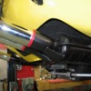
Here you can see the clutch slave cylinder with the rod fully adjusted in to minimum length. I had to shorten this by about 16mm to fit it back together with the rebuilt and sleeved slave cylinder.

All seems well. I have no clutch creep in neutral on a perfectly flat surface, gears select perfectly, and the only real issue is the clutch engages a bit high. Given what the manual says about correct clutch adjustment though, I'm a little concerned that I haven't got it adjusted right, and the manual instructions are a bit off!


The manual is far from clear on adjustment:

- Remove the adjustment stop screw and nut and discard!
- Remove rubber boot and back off the pushrod locknut.
- Adjust length of push rod to give 3/4" of free play and clutch pedal retaining locknut?

Now in that third instruction there has to be a typo, as that makes no sense, even to an Aussie.

Like what is the "clutch pedal retaining locknut"?

Attachments

Images (1)
  • IMG_0453
Okay, disregard the spring thing. I located in the parts manual that there are two springs. One on the brake and one on the clutch. I went back down and crawled under there and sure enuff, the brake spring is there. Two full loops and then a tab off one side that wraps around the pedal shaft.

Question is, if this part is available, can it be fitted without removing the pedal box? There appears to be a grub screw at the head of the clutch pedal shaft but unless this is on some sort of a keyway, removal in situ would appear to be very difficult.

Where would I try to locate this spring? Wilkinsons or maybe Kirk Evans?
quote:
The other thing to consider about the overall stance is that the top of the door (below the window frame) is not parallel with the bottom of the pitch weld. It angles up toward the front of the car, so the car will look like it is running up hill if the pinch weld is parallel to the ground. From my measurements and calculations a 1” difference between the front and back pinch weld equals 1 degree. Mine is a tad over 3/8” lower in front or .375+ degrees nose down. That stance puts the top of the door just very slightly lower in the front in relation to the ground.


Thanks Mike. By the door pinchweld, I take it you mean the one along the bottom of the door opening. Do you just lay a 3' level along there on flat ground and you set yours 3/8" lower at the front of the door opening? Over the length of the car this must relay to a lot lower at the front?

Quite difficult to set these cars to a 'proper' height as there really isn't any common points as the cars vary so much due to wheels / tyres / spoliers / body kits etc.
Post
×
×
×
×
Link copied to your clipboard.
×