.
Preface
This topic (thread) is NOT about hot-rodding the 351C. The topic is divided into 3 sections: Background, De-Smogging, and Durability. In providing background for the "De-Smogging" section the first section has become a primer for owners, who like me, are captivated by a 351C powered automobile.
The "De-Smogging" section suggests making the stock specification better, i.e. making it "Super Stock". Or to put that another way, allowing the engine to perform as it had been intended, or up to its potential. The premise is this: the difference between a car powered by a 280 horsepower 351 Cobra Jet having 8.0:1 compression and a car powered by a 350 horsepower 351 Cobra Jet having 10:1 compression is startling ... and thus something to consider.
Cleveland engines are usually referred to by their "engine code" which was the 5th digit of the vehicle identification number.
H code: US 2 bbl engines, '70 to '74.
K code: Australian 2 bbl engines, US imports '70 to '71, domestic '72 to '75.
-----------
M code: US 4 bbl engines, '70 to '71.
R code: US solid tappet 4 bbl engines (Boss/H.O.), '71 to '72.
Q code: US high performance 4 bbl engines (Cobra Jet), '72 to '74.
T code: Australian 4 bbl engines, US imports '70 to '74, domestic '73 to '84.
The preponderance of the information and suggestions herein are geared towards the US manufactured M code and Q code versions because they were equipped with 4V (large port) cylinder heads, they were mass produced, and they were installed in a wide variety of "performance" cars. This includes Australian T code engines which were imports from the US.
Of course, the information can be applied to other versions as well.
Enjoy
SECTION 1: Background
Influences
Looking back, two events stand-out as having had the greatest influence upon the existence and design of the 351C with 4V heads, and both involve NASCAR. The first was NASCAR's banishment of the 427 SOHC engine from NASCAR competition. The second was NASCAR's establishment of a "six-liter rule". That's where we'll start.
Wide-Open Induction Systems
Ford's race-engine engineering team designed the SOHC 427 circa 1964 to 1965 specifically for NASCAR competition, to compete against the Chrysler 426 hemi. The "cammer" as it was called, was rated at 657 horsepower @ 7500 rpm with dual 4 bbl carburetors. That was more horsepower than any NASCAR engine had made up to that point. However, NASCAR "banned" the SOHC 427. In response to NASCAR's banishment Ford's engineers sought to achieve the same performance without an OHC valve train.
The race-engine engineering team (or perhaps the sales and marketing group) gave their quest a name, it was a "wide-open induction system". The goal of a wide-open induction system was to achieve the induction system performance of an OHC cylinder head in an OHV (push rod) format.
The characteristics which gave an OHC induction system superior performance stemmed from the lack of push rods. The intake port had a straight, short, unrestricted pathway to the intake valve pocket, without a restriction in the intake port due to push rods and without bends in the intake port. The intake port shape was rounded, and its cross-sectional area would have equaled about 125% of the area of the valve pocket's minimum cross section (throat).
Ford's earliest wide-open induction system designs were the "tunnel-port" heads and "tunnel-port" intake manifolds designed for both the 427 NASCAR engine and the 302 small block Trans Am engine. Those heads and manifolds utilized push rod "tunnels" routed through the middle of the intake ports, thus the name "tunnel-port".
The 427 tunnel-port engine fared well in '68 NASCAR competition, with David Pearson taking the season championship over his Chrysler hemi powered rivals; something a Ford team hadn't accomplished since the 426 hemi was introduced in '64. That was a big validation of the "wide open induction system" concept. The 302 tunnel-port engine did not fare as well in '68 Trans Am competition.
Wide-open induction systems were not a concept exclusive to Ford; Pontiac engineers also developed a group of "unrestricted port" engines designated "Ram Air V" in 1969. Like Ford's tunnel-port induction, the Ram Air V engines had push rod "tunnels" routed through the middle of the intake ports.
The Six Liter Rule
By the mid to late 1960s race cars were circulating tracks at over 200 mph. The horsepower and speed of racing vehicles had advanced quickly and exceeded the safe limits for tire technology, aerodynamic technology, and safety equipment technology. NASCAR responded to this situation by discouraging "purpose-built race engines" such as Chrysler's 426 hemi and Ford's 427 SOHC; both were "banned" at the end of the '64 race season (the Hemi returned to NASCAR in '66 after it became a regular production option). NASCAR also incentivized race teams to downsize their engines. This went on for half a decade and culminated in a 1969 announcement that, effective 1971, the seven-liter V8s employed in Grand National Stock Car Racing would be fitted with restrictor plates between their carburetors and intake manifolds while engines displacing six liters or less would be allowed to operate without restrictor plates. That last provision was known as the six-liter rule.
Thus, NASCAR racing under the six-liter rule was the "raison d'être" of the 351C with 4V heads.
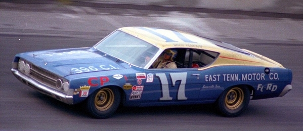
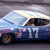
One NASCAR race of interest in '68 was the Rebel 400 held at Darlington on May 11th that year. David Pearson ran a special engine for that race, a "de-stroked" 427 displacing 396 cubic inches. The displacement was arrived at by replacing the standard 3.78-inch stroke crankshaft with a 3.50-inch stroke crankshaft. It was topped-off with either tunnel-port heads and intake manifold, or medium riser heads and a "tunnel wedge" (C8AX-9424-A) intake manifold. The eventual configuration of the 351C with 4V heads was comparable to the configuration of the 396 cubic inch engine powering Pearson's Torino that day (excepting for its bore diameter).
NASCAR lowered the minimum weight limit of Pearson's #17 Torino by 293 pounds due to the reduction in the engine's displacement. As a result of the weight reduction the tires lasted longer, the fuel went further, and the car cornered faster. Late in the race Pearson was running 2 laps ahead of the nearest competitor when his team instructed him to slow down, so he cruised to the finish line still 18 seconds ahead of second place as he crossed. It is possible that the configuration of the 351C with 4V heads was confirmed that day.
The 351 Cleveland was not just another production engine, it was a future NASCAR racing engine. The race-engine engineering team were involved from the project's inception. They had wanted to study canted valve heads since 1963. The wide-open induction system concept, and their experiences during the entire "Total Performance" era, including the '68 race season, influenced the design.
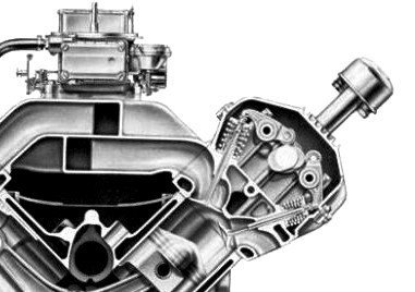
The 4V cylinder head was ingeniously designed to achieve a wide-open induction system without the need for push rod "tunnels". The canted valves spread the push rods apart, allowing the intake port to pass between the push rods unrestricted. The valve positions were rotated (clocked) to provide the intake port with a straight path to the valve pocket without bends. The intake valve was the size of the 427 medium riser intake valve (2.19-inches diameter). The intake port was the size of the 427 medium riser intake port at the push rods (3.14-in.2); but ahead of the push rods, i.e. between the push rods and the intake manifold flange, it expanded to the size of the 427 tunnel-port intake port (4.27-in.2).
3.14 square inches was the cross section of most of the high-performance FE V8 intake ports, including the 352 HP, 390 HP & 6V, 406 4V & 6V, 427 low riser, 427 medium riser, and the 428 CJ & SCJ.
By now it should be clear that (1) the 351C with 4V heads was designed for NASCAR racing, that (2) a lot of FE-427 design was carried over to the Cleveland, and that (3) the Cleveland had a wide-open induction system. Having a wide-open induction system meant (4) the induction system's performance was comparable to the performance of an OHC induction system ... without the overhead cams.
There is more.
The 351C was designed with a “controlled bypass” coolant system, the first Ford V8 to be so equipped. Such coolant systems are common today, but the 351C was the first on the block.
The 351C used a unique thermostat (Robertshaw # 333); it was NOT the same thermostat used by other small block Fords. It looked like a typical “high flow” Robertshaw thermostat until it was turned over exposing the flanged copper sleeve attached to the bottom. That flanged sleeve was there to shut-off the coolant bypass when the engine reached operating temperature. The wrong thermostat allowed too much coolant to constantly bypass the radiator, even when the engine was hot. Installation of the wrong thermostat was the most prevalent problem with the 351C; one created by the auto parts industry.
351C design began in earnest in '67, by the spring of '69 Cleveland 4V cylinder heads were readied for 302 Boss engines and the '69 Trans Am racing season. The '69 Boss 302 Mustang's engine was the first Ford production engine to be equipped with Cleveland 4V heads. The Boss 302 Mustang went on sale in the spring of '69, near the end of the production year.
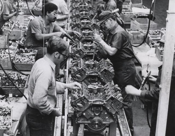
The earliest 351C production castings had July '69 and August '69 casting dates. 351C assembly began about September 1969 in a 510,000 square foot, $100 million dollar expansion of Ford’s Cleveland Engine Plant Number 2, by members of UAW local 1250.
In the late 1960s and early 1970s the consumer protectionist lobby and the insurance lobby campaigned against performance cars. Their stance that performance cars were dangerous gained influence. Executives in Dearborn were especially concerned about public opinion. They shut-down their racing programs and downplayed performance. Their curtailment in performance culminated with Corporate Ford issuing a memo on February 6, 1973, instructing all concerned to "effectively eliminate any financial participation in performance products, parts, or events as well as any communication related to performance activities."
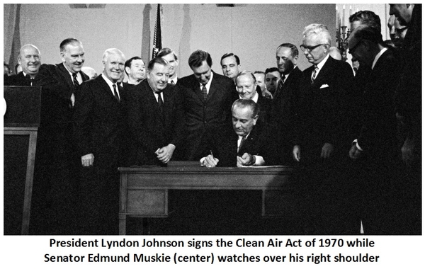
The environmental lobby's “Motor Vehicle Air Pollution Control Act” of 1965 had taken effect in 1968. Engine performance diminished year by year, but at a manageable pace. Then, in 1972, the "Muskie Act" took effect, with more stringent regulations which progressed at an accelerated pace.
The 351C was manufactured in the US during the time when US Ford was gradually downplaying the performance image of its cars and when "clean-air" measures were chipping-away at engine performance. The modest versions of the 351 Cleveland which were produced were built to "less than optimal" specification.
That is the "raison d'être" for the emendations suggested by this topic. ![]()
Terminology ... both confusing and humorous.
Ford manufactured three different 351 cubic inch V8s in the same time period. A letter in the engine description was employed to differentiate each engine from the other two. The first 351 Ford V8 was the 351W; "W" stood for Windsor, Ontario, Canada where it was manufactured. It went into production in '69, one year ahead of the 351C.
The "C" in 351C stood for Cleveland, because Cleveland, Ohio, USA is one of the cities where it was assembled. It was also assembled 10,000 miles across the world in Geelong, Victoria, Australia. That's right, the 351 "Cleveland" was assembled in "Geelong" Australia. Laugh.
The last 351 Ford V8 was the 351M. The 351M was assembled in Cleveland, in the same plant where the 351C had been assembled. 351M production began the year following the last year of 351C production. One thing we can be sure of, "M" did not stand for the name of the city where it was manufactured! There is literature, such as Ford Motorsport catalogs and Chilton repair manuals, where the 351M is described as "Modified" in quotations. The story goes that "M" stood for modified because that engine, though similar to the 351C, was assembled using a block with a taller deck height.
However, "M" may have been chosen simply because it was halfway between "C" and "W" in the alphabet. Laugh.
The term 351 4V referred to any 351 cubic inch Ford V8 equipped with a 4 bbl carburetor. Nowadays "4V" would mean 4 valves per cylinder, but back then "4V" meant "4 venturis". Each carburetor "barrel" was assumed to have a venturi.
1V = 1 bbl carburetor
2V = 2 bbl carburetor
3V = 3 bbl carburetor
4V = 4 bbl carburetor
6V = 3 two bbl carburetors (3 deuces)
8V = 2 four bbl carburetors (dual quads)
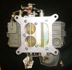
But Ford's 4300 series 4 bbl carburetors did not have venturis in the secondary throttle bores. So, they were 4V carburetors with only 2 venturis. Laugh.
If you're curious about the mention of a "3 bbl" carburetor, Holley made two of them, they were type 3160s; list 3916 was a 950-cfm carburetor, and list 4604 was a 1050-cfm carburetor. These carburetors were the reasons why dual plane intake manifolds of that era had notches in their plenum dividers. These were the "big carburetors" prior to the introduction of Holley's 4500 series (Dominator) carburetors.
The 351W was equipped with "4V" carburetion in '69 and the first half of '70, it was the first 351 4V. The 351C took its place.
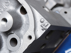
The 351 4V engines assembled in Cleveland Ohio were equipped with heads having raised intake ports with very large port entrances and relatively large intake port cross sections developed for NASCAR racing. Those heads were known as "4V" heads because they were standard equipment on 4V engines manufactured in the US, AND they had large numeral 4s cast into the upper corners of the head castings.
The 351M was never equipped with "4V" carburetion.
The Australian 351 4V was not equipped with 4V heads. The Australian 351 4V engines were equipped with the same heads as the 2V engines. The heads had lower intake ports and smaller intake port cross sections. In the US those heads were called 2V heads. So, the Australian 351 4V was equipped with 2V heads. No big deal to an Aussie, but to a Yank it seems like a mismatch. Laugh.
2V Cylinder Head and 4V Cylinder Head Comparisons
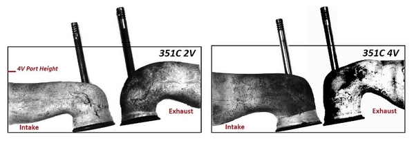
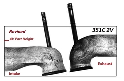
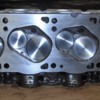
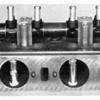
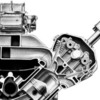
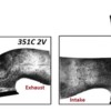
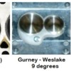
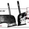
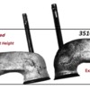
> Below is a picture of actual cylinder head port molds, put together to represent a 2V cylinder head and a 4V cylinder head.
On the left is the 2V intake port. Following the port floor to where it intersects the valve pocket, there is a rounded bend at that intersection. That's known as the "short turn". The radius of the 2V short turn was a very short radius, resulting in a very tight bend. In comparison, the radius of the 4V short turn was a large radius, resulting in a large well-rounded bend.
The 4V intake port roof was also a half inch higher than the 2V intake port roof, thus the gas column flowing through the 4V intake port had less of a turn to make in order to flow through the intake valve.
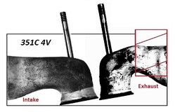
The 2V exhaust port roof formed a continuous arch from the valve seat to its apex. No criticism so far, unfortunately the port roof continued to arch beyond the apex, thus the exhaust port turned downward as it exited the cylinder head. The downward turn diminished the gas flow performance of the port.
Had the 2V intake port been designed with a short turn radius equivalent to the short turn radius of the 4V intake port and had the 2V exhaust port been straightened at the apex (raising the port roof about 0.200-inch at the flange), there would have been little left to criticize about the 2V cylinder head.
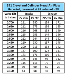
It is hard to believe the 4V exhaust port was designed by the same engineers who designed the 2V exhaust port, but it was. It "looks" strangely designed. The race-engine engineers wanted a "high exhaust port" for their NASCAR cylinder head, but the engineering committee wouldn't agree to it. So, their solution was to design the production 4V exhaust port to be capable of modification with "exhaust port plates". In spite of its strange design, an unported 4V exhaust port flowed about 10 cfm better than an unported 2V exhaust port.
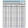
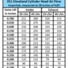
> Here's intake port and exhaust port air flow comparisons, based upon 1970-cylinder head castings, unported and unmodified, measured at 28 inches of water.
Three angle valve seats combined with valve pocket and combustion chamber blending (porting) improve the flow numbers by about 15% (40 to 50 cfm).
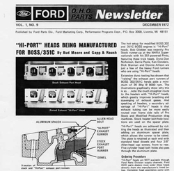
> Ford's first sales document for 351 Cleveland performance parts was Autolite publication MP-1046, which was published circa 1970. Of interest, that document reported the following gains for '70 H code engines (rated 250 horsepower) and '70 M code engines (rated 300 horsepower).
• 780 Holley carburetor: +35 horsepower (2V) +11 horsepower (4V)
• GT (Cobra Jet) hyd. tappet cam: +29 horsepower (2V) +39 horsepower (4V)
• 351 Boss solid tappet cam: +49 horsepower (Same for 2V & 4V)
• 2-inch ID x 34-inch length tube headers: +15 horsepower (Same for 2V & 4V)
Interesting Point: Raising the compression of a 285-horsepower engine from 8.4:1 to 10.0:1 increases output by 6.5 horsepower; the new output would be 291.5 horsepower.
The 6.5 horsepower gain was arrived at using the calculator at Wallace Racing's website. Wallace Racing - New HP From a Change in Comp Ratio
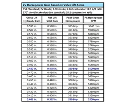
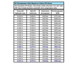
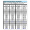
> Here are tabulations of horsepower gain based on valve lift alone, for both 2V and 4V heads.
> As a means to depict the differences between 2V heads and 4V heads; imagine two 351 Cleveland engines, one equipped with 2V heads and another equipped with 4V heads. Imagine building both to the same factory performance specification; the “Cobra Jet” specification. Describing the results describes the difference between the cylinder heads.
The engine with 2V heads shall produce 320 horsepower at 5500 rpm, the engine with 4V heads shall produce 350 horsepower at 5800 rpm. In this 0.481-inch lift street application the 4V heads are worth 30 horsepower.
Since both engines have 10:1 compression, their dynamic performance (i.e. low-end torque, pep, acceleration and throttle response) shall be similar. The 2V powerband occurs about 300 rpm lower than the 4V powerband. The power delivery of both engines is strong, but their delivery is different.
The 2V engine delivers its power a little less vigorously, more smoothly, some describe it as being more "refined". Equipped with NASCAR racing heads the 4V engine delivers its power more vigorously. It comes on the cam harder, and it pulls "stronger and longer" at high rpm. Some call it a "charging rhino". Others prefer the power delivery of the 2V engine.
The 351 Cobra Jet
A Cobra Jet spec was mentioned previously and shall be referenced in further sections. Thus, it deserves an explanation. It's a "factory" state of tune going back to '66. It was the spec for many of Ford's high-output engines of the 1960s.
The Cobra Jet state of tune was made possible by a high-lift, short duration (high lift rate), hydraulic camshaft lobe utilized for the intake valve, and a valve spring with a flat-wound damper capable of controlling the high lift rate intake valve. They were state-of-the-art components back in '66.
The Cobra Jet state of tune is a "middle of the road" state of tune between a standard 4V engine and a solid tappet 4V engine. It was "too much engine" for some motorists. It was a low maintenance high performance engine which remained tractable enough for daily driver applications, yet it was only down 10 to 20 horsepower compared to the "hotter" solid cam engines.
The Specification:
(1) A Holley style square bore, dual plane, 4 bbl intake manifold.
(2) A 650-cfm vacuum secondary (non-emissions) Holley carburetor.
(3) The static compression ratio set at nominally 10:1. Raising the compression ratio provides the "dynamic performance" people are looking for.
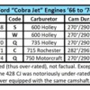
(4) A Q code (Cobra Jet) camshaft. 270°/290° duration, 0.481/0.490-inch lift, 46° overlap, and 117° LSA. The LSA of replacement cams is usually 115°.
(5) The cam timing advanced 4° to 8°. The IVC should occur no earlier than 66° ABDC, but no later than 72° ABDC. The dynamic compression is set ≤ 8:1.
(6) 2V cylinder heads upgraded with 4V rocker arm fulcrums, valve springs, retainers, and locks.
(7) Duraspark I or Duraspark II breakerless electronic ignition. The Cobra Jet engines were historically equipped with dual point ignitions; but the Duraspark ignitions are better performing than dual points.
(8) Dual exhaust (dual 2.25-inch to 2.50-inch tail pipes).
• A Cobra Jet engine employing 2V heads = 320 horsepower.
• A Cobra Jet engine employing 4V heads = 350 horsepower.
Note: Adding a 0.550-inch (14 mm) lift short duration and low overlap camshaft to the engine with 2V heads makes-up the 30-horsepower deficit. A hydraulic roller cam version can be ordered, custom made, by Bullet Racing Cams utilizing lobes # HR270/320 and #HR290/320B, 115° LSA, indexed straight-up or 4° advanced.
Assembling a 351C to the Cobra Jet spec requires substituting the engine's carburetor and raising its compression. To accomplish those changes most often requires changes to the intake manifold and cylinder heads. Here's information regarding the parts required.
Square Bore 4 bbl Intake Manifolds for 2V Cylinder Heads:
• The Australian Ford iron 4 bbl manifold installed on XB Falcon GTs
(casting # 73DA-9425-AB).
• The Ford Motorsport # M-9424-G351 manifold; discontinued.
(Same as Edelbrock # 2750).
• The Edelbrock Performer 351-2V manifold # 2750.
Quench Chamber 2V Cylinder Heads:
• Australian Ford 302C (Y code & P code) heads, (57.9 cc).
• Ford Motorsport part number M-6049-C351 heads (62.0 cc).
Square Bore 4 bbl Intake Manifolds for 4V Cylinder Heads:
• The US Ford iron 4 bbl manifold installed on '70 and '71 M code engines
(casting # D0AE-9425-L).
• The US Ford aluminum 4bbl manifold part # D1ZZ-9424-G; discontinued.
(casting # D1ZX-9425-DA).
• The Edelbrock Performer 351-4V manifold # 2665.
Quench Chamber 4V Cylinder Heads:
• US Ford 1970 M code heads: D0AE castings, (62.8 cc).
• US Ford 1971 M code heads: D1AE castings, (66.1 cc).
NOTE: The Australian Ford and US Ford iron intake manifolds were "four hole" style manifolds designed for Autolite/Motorcraft 4300A carburetors. The primary holes of those manifolds need to be enlarged to 1.69-inches diameter (43 mm). The heat passage in front of the primary holes should be plugged as well.
Fast Company: Cars Powered by 351Cs with 4V Heads
The '70 to '74 vehicles powered by 351Cs with 4V heads encompassed more than just Mustangs and Torinos.
• US Ford – Ford Division: Mustang, Torino, and Ranchero
• US Ford – Mercury Division: Cougar and Montego
• Ford of Australia: XW, XY, XA, XB Falcons (and Fairlanes)
• Bolwell (Australia): Nagari
• De Tomaso (Italy): Pantera, Longchamp, and Deauville
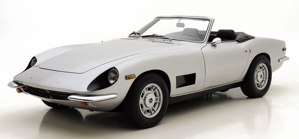
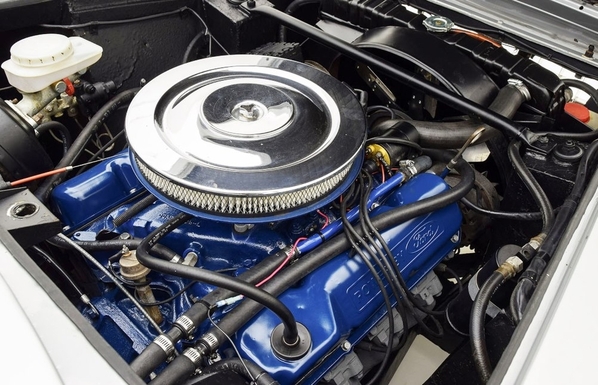
• Intermeccanica (Italy): Italia
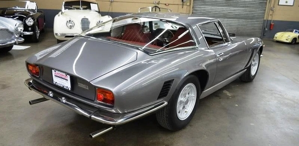
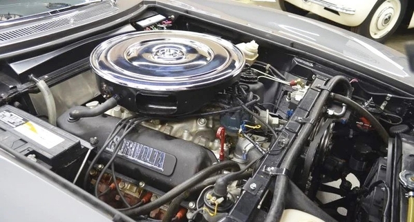
• Iso Rivolta (Italy): Lele, Fidia and Grifo
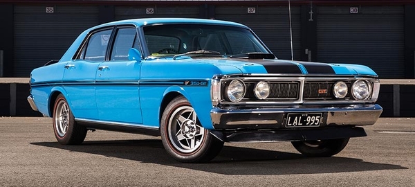
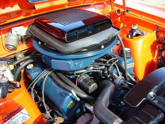
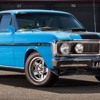
Amongst the "fast company" of cars powered by 351Cs with 4V heads were the '71 XY Falcon GT/HO phase IIIs. They were the world's fastest four-door production cars back then.
The '71 XY Falcon GT/HO phase IIIs were powered by US manufactured M code engines modified by Ford of Australia with R code (351 Boss) solid tappet valvetrain and 780 Holley carburetors. The R code camshaft spec was 290°/290° duration, 0.477/0.477-inch net lift, 116° LSA.
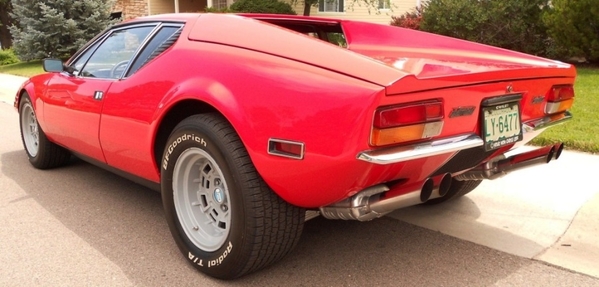
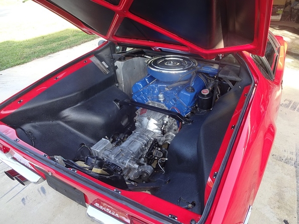
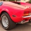
1971 De Tomaso Pantera!
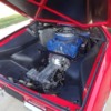
You get a different view of the engine in a Pantera.
1972 Iso Rivolta Grifo, Series II
1972 Intermeccanica Italia Spyder
Net Horsepower Confusion
The output of the M code engine was rated 300 gross horsepower in '70 and 285 gross horsepower in '71. Although never advertised, the "gross power" rating of the Q code engines in '72 and '73 was 280 gross horsepower.
When "net horsepower" ratings came into usage in '72 and '73, there were two power ratings quoted for the Q code engine, 266 net horsepower and 246 net horsepower. This has been a source of confusion.
The higher "net power" rating (266 net horsepower) was only down from the gross power rating by 14 horsepower. This applied to Mustangs and Cougars.
The lower rating (246 net horsepower) was down from the gross power rating by 34 horsepower. This applied to the intermediates (i.e. Torinos, Montegos, and Rancheros).
The extent to which power ratings declined due to the use of “Net Ratings” depended upon which power robbing accessories were deemed standard equipment. The difference in net power ratings between the Mustangs/Cougars and the intermediates was due to power steering, which was optional in Mustangs and Cougars, but standard equipment in the intermediates.
The Mustang was downsized in '74, it became the "Mustang II", which was a repackaged Pinto. The 351C was not available in the Mustang II. The Cougar name was repurposed in '74; it was applied to an intermediate slotted above the Montego. So, while the Mustang became a Pinto, the Cougar became a 4300-pound intermediate, the Mercury counterpart to the Ford Gran Torino Elite.
In '74 there was a single power rating, 255 net horsepower. Since the Mustang and Cougar both "morphed" into different cars in '74 it is only logical that the new power rating applied to the intermediates. If the 34 horsepower "loss" from the '72 and '73 intermediates is added to the 255 net horsepower rating, it follows that the gross output in '74 was 289 gross horsepower.
Power was up from the 280 gross horsepower rating of the previous two years because the '74 engines were only tuned to pass the federal (49 state) emissions certification; the Q code engines were not certified for sale in California in '74. This is why '74 Panteras destined for California were re-documented as '73 Panteras.
Expressing the output of the various factory 351C engines with 4V heads in the same terms (gross horsepower) hopefully puts an end to the confusion over 351C power ratings. None of the US manufactured 351C 4V engines made less than 280 gross horsepower.
Comparing the gross horsepower ratings to the "potential" output of each engine also makes the power losses due to emissions tuning very clear.
• 1970 M code: an engine with 310 HP potential which made 300 gross HP.
• 1971 M code: an engine with 310 HP potential which made 285 gross HP.
• 1971 R code: an engine with 360 HP potential which made 330 gross HP.
• 1972 R code: an engine with 365 HP potential which made 289 gross HP.
• 1972 Q code: an engine with 350 HP potential which made 280 gross HP.
• 1973 Q code: an engine with 350 HP potential which made 280 gross HP.
• 1974 Q code: an engine with 350 HP potential which made 289 gross HP.
Power loss, year by year, in percentages:
• 1970 M code: 3.2%
• 1971 M code: 8.1%
• 1971 R code: 8.3%
• 1972 R code: 20.8%
• 1972 Q code: 20%
• 1973 Q code: 20%
• 1974 Q code: 17.4% (49 state tune)
Power losses jumped from 8% in 1971 to 20% in 1972. That was the year the "Muskie Act" kicked in. It was a "disastrous year" for engine performance in the US (equivalent to 1976 in Australia). All of the power losses were attributable to emissions tuned carburetors and lowered compression ratios. The carburetors have always been the biggest problem.
Carburetor and Induction System Info circa 1970
Autolite was Ford's parts division prior to 1972, as such they managed the performance parts program. Testing of the '70 M code 351C conducted by Autolite, reported in Hot Rod magazine's August 1970 issue ("Put-Ons for Ford of Cleveland"), yielded these results on the subject of carburetor swapping:
• 600 Holley vacuum secondary (emissions-tuned) carburetor: –4 horsepower
• 780 Holley list 3310 (non-emissions) carburetor: +9 horsepower
• 850 Holley list 4781 (non-emissions) carburetor: +16 horsepower
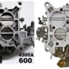
In the 1970s Holley released several 600 cfm 4bbl carburetors with vacuum secondaries; they were 4160 style carburetors (no secondary metering plates), they had electric chokes, side hung floats and single feed fuel connections. They were all emissions tuned carburetors. The list 6619 was commonly used to replace the Autolite/Motorcraft carburetors installed on 351Cs.
Replacing an emissions carburetor with another emissions carburetor doesn't accomplish much, unless the carburetor being replaced is calibrated extremely lean. That wasn't the situation in 1970, the '70 M code engine lost 4 horsepower when Autolite tested the 600 Holley carburetor.
Replacing an emissions carburetor with a non-emissions carburetor should see a gain in horsepower equivalent to the power loss due to emissions tuning. The '70 M code engine gained 9 horsepower when Autolite tested the 780 Holley carburetor. The magazine article mentioned that the intake manifold inlets were milled out to accommodate the larger throttle plates of the Holley carburetor.
The 780 Holley vacuum secondary carb yielded the best results during their testing. A 780-cfm carburetor was too big for a stock M code engine, but the 780 Holley carburetor was a unique carburetor; it was big enough for just about any application, but its vacuum secondaries prevented it from being bigger than an application required, consequently making it a one size fits all carburetor.
The '70 M code engine gained 7 horsepower above the output achieved with the 780 Holley carburetor, when Autolite tested the 850 Holley carburetor. But Autolite reported the powerband narrowed and the carburetor was too large for the engine and camshaft combinations being tested. A 351 cubic inch engine making 360 peak horsepower at 5800 rpm doesn't need an 850-cfm carburetor, not even the 351 Boss. Ford's first high performance engine, the "352 High Performance" of 1960 (aka the 352 Super V8), made 360 horsepower equipped with a Holley carburetor rated merely 540 cfm. The "W code" 427 of 1968 made 390 horsepower equipped with a Holley carburetor rated 600 cfm.
This brings up an important concept, carburetors do not make horsepower. If a carburetor is sized properly and well-tuned, then it shall "stay out of the way" and simply allow (or enable) an engine to perform its best. The best carburetor is one that "stays out of the way".
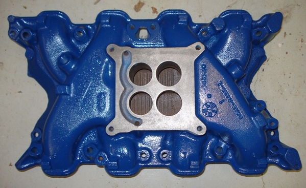
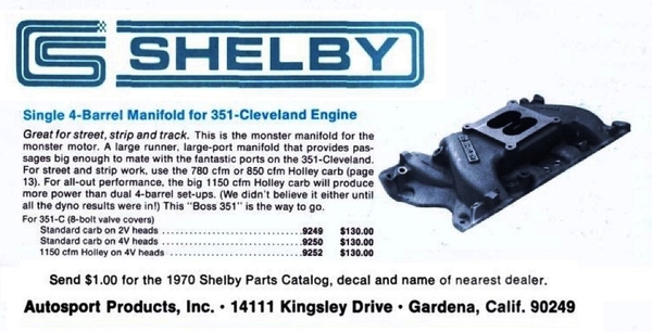
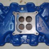
One last item of interest to mention regarding the 351C induction system. The engineers who designed the 351C designed a high-rise intake manifold for it. You may recognize it as the "Blue Thunder manifold".
It is likely that the high-rise manifold had been intended to be the 351 Boss intake manifold.
Either the manifold was pulled from the production engine, or it was never intended to be a production part. However, someone at Ford decided to make the high-rise manifold available to the public via aftermarket sales. Autolite was geared towards marketing "production parts", thus the high-rise manifold was sold via Shelby/Autosport Products, which marketed "non-production" parts.
Shelby/Autosport Products Inc. had been established to create a layer of separation between the sale of high-performance parts and Ford but make no mistake, Shelby/Autosport Products Inc. was owned by Ford. The high-rise manifold was originally badged as a Shelby manifold and had a casting number of 351D-9424-D on the # 1 runner. In the '80's and '90's it was sold by Ford Power Parts, and it has been sold in recent decades by Price Motorsports and under the Blue Thunder name.
Ford Power Parts performed an intake manifold comparison test, reported in the October 1993 issue of Super Ford magazine ("Planes of Power"). Testing was performed using an engine equipped with an 0.698-inch lift solid roller cam (a BIG cam). The Blue Thunder manifold increased the engine's output by 39 horsepower (!) compared to the standard height Ford aluminum dual plane manifold, casting # D1ZX-9425-DA. It was up from 451 horsepower to 490 horsepower, an 8.7% gain. A more "modest" engine, such as a Cobra Jet spec engine, will of course produce more modest results; perhaps 28 horsepower (8% of 350 horsepower).
The "Blue Thunder manifold" is a piece of 351C history. It's very cool that it has survived 50 years and that it is still popular. Kudos to Art Francis.
4300 Series Carburetors
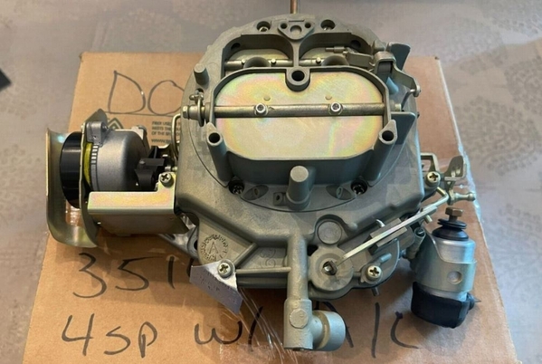
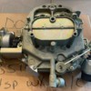
The Autolite/Motorcraft 4300 series carburetor was manufactured from 1967 through 1974. It was an “air valve” carburetor like the Carter/Edelbrock AVS carburetor or the Rochester Quadrajet; consequently, the secondary barrels had no main venturis. The secondary throttle plates were actuated by direct linkage, but secondary air flow was controlled by “air valves” above the throttle plates.
Ford issued several technical service bulletins regarding these carburetors, mostly dealing with poor or rough engine performance, plus hesitations and flat spots on light acceleration.
Another issue with the carburetors was fuel puddling in the intake manifold. After a car was parked the heat from the engine would percolate the fuel in the fuel bowl, which spilled over and puddled in the intake manifold. This made the engine difficult to restart after a "hot soak".
The carburetor's performance was also claimed to have been afflicted by an engine "stumble" or "bog" which manifested when a car accelerated hard. Some blamed this on fuel bowl design (capacity), others on the accelerator pump, and others on the secondary air valve operation.
Instead of having dual high-capacity fuel bowls, like the Holley 4150/4160 and Autolite 4100 carburetors, the 4300 series carburetor had a single low-capacity fuel bowl with staged dual inlets to reduce "evaporative emissions". The fuel bowl wrapped around the front of the carburetor, and the fuel level was controlled by a "pontoon" style float assembly. Most rebuild kits eliminate the dual inlet design with a single inlet valve of greater capacity, whether that's good or bad I can't say. NAPA rebuild kits are reported to retain the original dual inlet design.
The 4300 carburetor was designed specifically to comply with the “Motor Vehicle Air Pollution Control Act” of 1965. It had features which allowed "a higher degree of control over the unburned hydrocarbons emitted in the exhaust”.
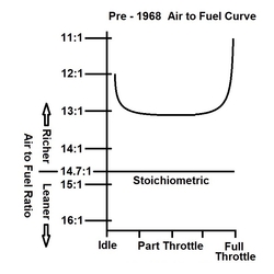
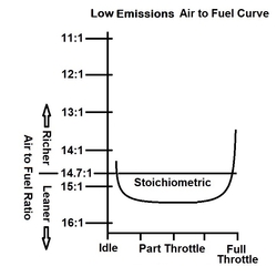
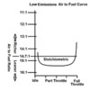
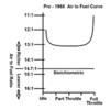
A carburetor's typical air fuel curve is "fishhook" shaped. It is rich at idle, even richer at full throttle, and is less rich at part throttle. Notice on the "Pre-1968" curve the entire curve is above the line labeled "stoichiometric". Stoichiometric means there is exactly enough air to completely burn each molecule of fuel. In the real world, to extract the best performance from an internal combustion engine, the air to fuel ratio must be quite a bit richer than stoichiometric. There must be enough fuel to consume all the air molecules. The remaining fuel molecules exit the exhaust as hydrocarbon emissions.
The air fuel curve of carburetors tuned to reduce emissions was simply moved lower on the scale; idle was leaner, full throttle was leaner, and part throttle became so lean that the air fuel ratio was leaner than stoichiometric, there was an excess amount of air. The purpose for leaning-out the air/fuel curve was to reduce the quantity of pollutants (hydrocarbons) dumped into the air. The leaned-out air/fuel curve made it necessary to lower compression ratios; and it worsened fuel efficiency. This shall be explained more thoroughly in a later section.
All carburetors installed on "post-1967" production automobiles were tuned this way; including the Holley carburetors which had been installed on muscle car engines.
The 4300 series carburetors were manufactured in three sizes which is reminiscent of the story of Goldilocks and the three bears; one was too small, one was too large, and one was just right.
The earliest and smallest 4300A carb was manufactured from 1967 to 1969. It had 1.00-inch primary venturis, 1.44-inch primary throttle bores, and 1.56-inch secondary throttle bores. It was rated at 446 cfm in the 1968 Ford engine manual and 470 cfm in the 1969 engine manual.
A larger 4300A carb was introduced a year later, in 1968. It had 1.25-inch primary venturis, 1.56-inch primary throttle bores, and 1.69-inch secondary throttle bores. The Ford engine manuals progressively rated the carburetor at 595 cfm, then 600 cfm, and finally 605 cfm.
The largest carburetor, the 4300D version, was introduced in 1971 in conjunction with the 351 Boss (R code) engine. It had 1.25-inch primary venturis, 1.56-inch primary throttle bores, and 2.00-inch secondary throttle bores. Some sources rate this carburetor at 715 cfm. It was rated 750 cfm several times in Ford literature but the '72 – '74 shop manuals provided no data to confirm either rating.
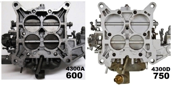
The 4300A carburetors were technically spread bore carburetors but there was very little difference between the sizes of the primary throttle bores and the secondary throttle bores. Visually the difference was very subtle. The carburetors mounted on Holley style square bore intake manifolds.
The 4300D carburetor was quite obviously a spread bore carburetor, there was a large difference between the sizes of the primary throttle bores and secondary throttle bores. The 4300D carburetor required a unique spread bore intake manifold which was incompatible with any other carburetor.
It is quite easy to differentiate between a 4300A and 4300D carburetor when the carburetors are flipped over due to the large secondary throttle bores of the 4300D. When the carburetors are right side up, they can be differentiated by the location of the secondary air valves. The 4300A secondary air valves are positioned below the booster venturis whereas the 4300D secondary air valves are positioned above the booster venturis.
Autolite 4300 Carburetor Idle Air/Fuel Ratios
• 1967 – Sorry, no data at this time
• 1968 – Between 13.2:1 and 14.4:1.
• 1969 – Between 14.0:1 and 14.8:1.
• 1970 – 351C, 429, 460 applications: Between 12.05:1 and 12.8:1
351C manual trans applications: 13.15:1
428 Police applications: 14.3:1
• 1971 – 14.2:1 or leaner
• 1972 through 1974 – Air/fuel ratios were not published.
Judging by the "idle" air/fuel ratios 1970 seems to have been the “best" year for 4300 series carburetor jetting (excepting 428 Police applications). They were jetted richer in 1970 than in previous years or in subsequent years. They were even jetted richer than the Holley carbs Ford used in 1970 on the 302 Boss, 429 Boss, 428 Cobra Jet, and the 428/429 Super Cobra Jets.
The name of Ford’s parts division changed from Autolite to Motorcraft in 1972, the same year the Muskie Act took effect. Therefore 4300 series carburetors branded “Motorcraft” were calibrated significantly leaner than those branded “Autolite”.
Since the air/fuel ratios of the 4300D carburetors were unpublished, we can only judge them by how much an engine's horsepower rating had decreased. The tune of the 1971 Autolite 4300D version installed on 351 Boss engines was down by 30 horsepower (8.3%). In spite of their air flow ratings the tunes of the ’72 and ’73 Motorcraft 4300D versions were down by 70 horsepower (20%), and the “49 state” tune of the ’74 Motorcraft 4300D version was down by 61 horsepower (17.4%).
Bigger carburetors are not always better, a carburetor's air/fuel ratio is more important than its air flow capacity. The 351 Boss would have made 18 additional horsepower if it had been equipped with the 600 cfm 4300A carburetor from the 1970 M code engine rather than the 750 cfm 4300D carburetor it had been equipped with.
Plummeting Compression Eradicated "Dynamic Performance"
Relatively high compression, requiring "premium" fuel (US/Canadian fuel rated 91 R+M/2 or international fuel rated 95 RON), is what gave 4 bbl carbureted engines the low-end torque, pep, acceleration and throttle response people expected when they purchased such engines from any auto manufacturer. Lowering the compression ratio of emissions tuned engines robbed them of those "dynamic performance" characteristics.
If the 4V engine in your car feels "sluggish" don't blame the intake ports, the low compression is responsible for the sluggishness.
Low compression was not mandated by the Muskie Act. But the compression ratios of engines equipped with "emissions tuned" carburetors had to be lowered due to the "leaned-out" part throttle air/fuel curve. Lowering the compression ratios prevented knocking, pinging, and detonation. Fuel economy plummeted in this era because some of the heat which should have been transferred into kinetic energy heated the excess air instead and flowed out the tail pipe. The addition of exhaust gas recirculation (EGR) in 1973 further diluted the part throttle air fuel mixture, which made it necessary to further reduce the compression ratio. Consequently, more heat which should have been transferred into kinetic energy reheated the recycled exhaust gases instead and flowed out the tail pipe.
SECTION 2: De-Smogging
Putting It in Reverse
Reversing the effects of emissions legislation is a matter of fitting the engine with a non-emissions carburetor with about 12:1 A/F ratio and afterwards raising the compression ratio. Installation of a non-emissions carb will restore the horsepower lost to emissions tuning AND makes it possible to raise an engine's compression without the risk of knocking, pinging, and detonation. Raising the compression restores the low-end torque, pep, acceleration and throttle response enthusiasts desire. This makes a big difference in the "dynamic performance" of any engine, the 351C equipped with 4V heads is no different.
It is an important concept that should be emphasized ... lean air/fuel mixtures are not compatible with higher compression ratios. To raise the compression of an engine it must first be fitted with a non-emissions carburetor. Those old Motorcraft carbs with their "leaned-out" part throttle air/fuel curves are boat anchors.
Now THIS is a Carburetor
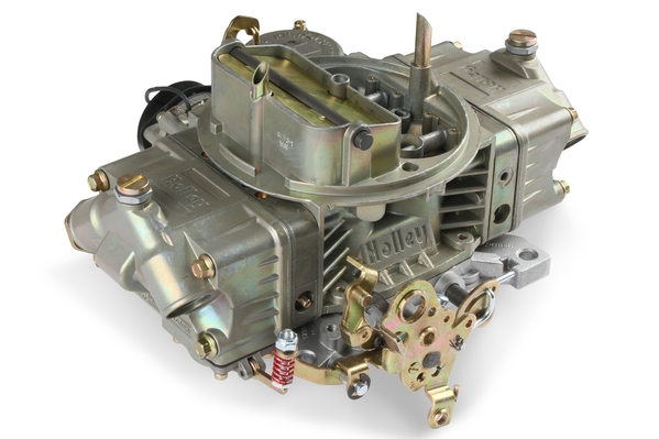
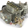
Holley's # 0-80783C carburetor might be the best "performance street carb" they've ever manufactured. It's designed to "stay out of the way". It is rated 650 CFM; it is sized appropriately for a 351 cubic inch engine with a 6000 rpm to 6500 rpm rev limit. Coincidentally, De Tomaso equipped the GTS, GT5, and GT5-S Panteras with 650 cfm Holley carburetors (list R4777).
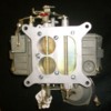
Holley's # 0-80783C carburetor is a 4150-style carburetor with dual metering blocks; it has center hung fuel bowls, vacuum secondaries, an electric choke, and it has a chromate finish. It looks like a factory original Holley carb from the late 1960's; for a 351C 4V application you could say it looks "period correct". It doesn't have annular booster venturis, but those aren't necessary unless the exhaust heat is blocked from the intake manifold. The carburetor can be custom ordered with annular boosters if they are desired or needed.
Replacing the carburetor with a square bore Holley carburetor will in many circumstances require a replacement intake manifold. A list of intake manifolds was provided previously under the "351 Cobra Jet" heading.
The Carter # M6882 fuel pump is the replacement when a new fuel pump is needed for a de-smogged 351C.
Raising the Compression Ratio
Raising the compression of an engine does not increase the horsepower to the extent some people believe. For instance, raising the compression of a 280-horsepower engine from 8.0:1 compression to 10.0:1 compression only raises the output by 9 horsepower. However, raising the compression improves the "dynamic performance" of an engine immensely in terms of low-end torque, pep, acceleration and throttle response.
To illustrate this point further, enthusiasts who drive their cars would be happier if the car was equipped with a 300-horsepower engine having 10:1 compression than they would be if the car was equipped with a 400-horsepower engine having 8:1 compression. Compression makes the difference!
Adjusting Perception
There are two things to become accustomed to as you continue reading.
First, no auto manufacturer's sales department ever published dynamic compression ratios, although their engineering departments used dynamic compression ratio to determine what fuel octane an engine required.
Second, the static compression ratios being quoted are factual, real-world compression ratios; not the grossly exaggerated advertised compression ratios that US Ford published through 1971.
Most of the high compression engines of the 1960s operated on "premium" gasoline, that indicates their dynamic compression ratios were in the range of 7.0:1 to 8.0:1. Fuel rated "regular" was for engines having 7.0:1 dynamic compression or less. Fuel rated "super-premium" was for engines having dynamic compression greater than 8.0:1. Very few engines were ever designed for "super-premium" fuel. Ford specified premium fuel for the 1970 351C. The sales department's claim that it had 11:1 compression was never possible.
Mass produced engines are built with tolerances. The 1970 M code engine had between 9.30:1 and 10.02:1 static compression, 9.65:1 being the nominal value. The engine's dynamic compression was between 7.14:1 and 7.67:1, 7.40:1 being the nominal value.
Limits
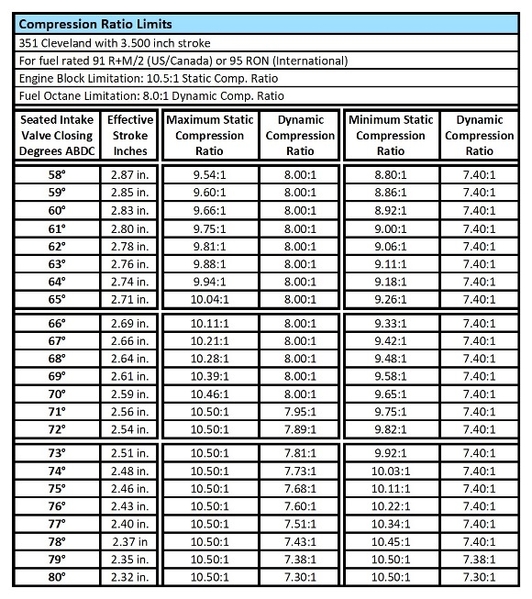
The Cleveland cylinder wall thickness specification was 0.160 inch +/- 0.030 inch. The cylinder walls could have been as thin as 0.130 inch in spots, right off the assembly line. That is literally half as thick as they should have been. This limits how high the compression ratio can be safely raised without incurring cylinder wall damage. That limit is traditionally 10.5:1 static compression.
There is another limit based upon fuel octane. The "safe" upper limit for fuel rated 91 R+M/2 (US/Canada) or 95 RON (International) is 8.0:1 dynamic compression. Dynamic compression is based on "effective stroke"; thus, it varies depending upon how early or how late the intake valve closes.
With high performance (Cobra Jet) street engines, short intake duration and early opening intake valves are usual, thus IVC's between 66° and 72° are common. A static compression of 10:1 produces dynamic compression ratios between 7.92:1 and 7.53:1, respectively. However, 10:1 compression is not exactly 10:1 compression. It varies based on the diameter (over-bore) of the cylinders. In the strategies suggested further below static compression can be as low as 9.84:1. A "worst-case" scenario combining 9.84:1 static compression with a 72° IVC produces a dynamic compression ratio of 7.42:1. That's still OK. It's still in the range that requires premium gasoline.
As a point of reference, the two 351 Cleveland engines with the highest static compression, the 1970 M code and the 1971 R code (351 Boss) had dynamic compression ratios of 7.40:1 and 7.43:1, respectively.
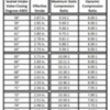
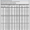
This useful table details the real-world impact of these limitations:
Engines with 8.0:1 dynamic compression shall have 163 psi cranking pressure during a compression check. Pressures higher than that indicate too much dynamic compression.
Seated Intake Valve Closing (IVC)
• M code camshaft: 70° ABDC
• Q code camshaft: 76° ABDC
• Q code camshaft advanced 4°: 72° ABDC
• Q code camshaft advanced 8°: 68° ABDC
• Q code replica hydraulic roller cam: 66° ABDC
Cylinder Heads
The breakdown of 4V cylinder head data.
Quench Chamber (M code) Heads
• 1970 M code: D0AE castings, 62.8 cc chamber volumes, 2.19/1.71 valves
• 1971 M code: D1AE castings, 66.1 cc chamber volumes, 2.19/1.71 valves
• 1971 R code: D1AE castings, 66.1 cc chamber volumes, 2.19/1.71 valves
Open Chamber (Q code) Heads
• 1972 R code: D1ZE castings, 75.4 cc chamber volumes, 2.19/1.71 valves
• 1972 Q code: D1ZE castings, 75.4 cc chamber volumes, 2.19/1.71 valves
• 1973 Q code: D3ZE castings, 78.4 cc chamber volumes, 2.041/1.655 valves
• 1974 Q code: D3ZE castings, 78.4 cc chamber volumes, 2.041/1.655 valves
The 1970½ and 1971 M code engines and the 1971 R code engines were the only 351 Cleveland engines equipped from the factory with quench chamber heads; they supposedly accounted for only 30% of the Cleveland engine production during that year-and-a-half. Consequently, there are not a lot of quench chamber heads to go around. Quench chamber 4V heads were always challenging to find, but with patience and diligence they could be found.
Far more 351 Cleveland engines were manufactured with open chamber heads. Raising the engine's compression with open chamber heads can be accomplished in two ways. (1) The first way requires zero-decking the block. That involves machining the decks and installing aftermarket flat top pistons with about 1.670-inch compression height. The new pistons will make it necessary to re-balance the reciprocating assembly. (2) The second way employs pop-up dome pistons, which again makes it necessary to re-balance the reciprocating assembly.
There is no way to avoid purchasing an expensive set of pistons or to avoid re-balancing the reciprocating assembly when raising compression with open chamber heads.
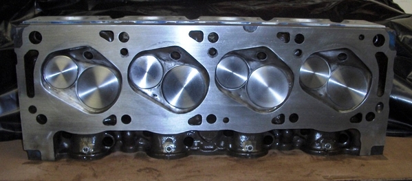
ALL Cleveland heads (excepting 302C heads) need some amount of milling to reduce their chamber volumes. BUT quench chamber heads don't require milling the block or re-balancing the reciprocating assembly. If dished pistons need to be replaced, you'll only need an inexpensive set of cast flat tops which weigh the same as the dished pistons (about 616 grams).
For this topic the focus shall be upon using quench chamber heads, i.e. the M code heads. That's both the easier strategy for raising compression and the historic (old school) strategy.
The M code heads had casting numbers of D0AE (1970, 62.8 cc nominal chamber volume) and D1AE (1971, 66.1 cc nominal chamber volume). Milling 0.020-inch off the D1AE head casting reduces the chamber volume to equal that of the D0AE head casting. Both heads are normally milled to achieve nominal 61 cc chamber volumes: 0.010-inch from the D0AE casting, and 0.030-inch from the D1AE casting.
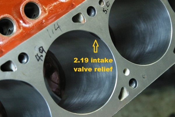
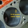
The M code cylinder heads are equipped with large 2.19-inch diameter intake valves. The valves are so large they require small reliefs ground into the top edges of the cylinders adjacent to the intake valves. The '73 and '74 Q code short blocks were originally equipped with small valve heads. So, when installing M code heads on the '73 and '74 Q code short blocks those small reliefs must be ground at the tops of the cylinders.
Over-Bores
The static compression ratio is also impacted by how much (if any) the cylinders have been over-bored. The compression increases as the amount of over-bore increases. When the compression becomes too high for a given IVC a swap to a thicker head gasket lowers the compression back into range.
Head Gaskets
0.047-inch compressed thickness (10.2 cc) was the thickness of the OEM head gaskets. It is also the thickness of the popular Fel Pro # 8347 PT-1 composite head gaskets.
0.038-inch compressed thickness (8.2 cc) was the thickness of Ford’s over the counter D3ZZ-6051-A head gaskets and of McCord’s # 6850 head gaskets; both of which you may have seen recommended in ‘70’s and ‘80’s literature. Edelbrock (# 7328) and Mr. Gasket (# 5808G) offer composite head gaskets in that thickness today.
10:1 Compression Strategies
The math equation for compression ratio is: (Vs + Vc) ÷ Vc
Where Vs is the swept volume of one cylinder and Vc is the clearance volume for one cylinder. The Vs increases as bore increases. The swept volumes for a 3.500-inch stroke, and the common bores are:
Vs for a std. 4.000 bore = 721.0 cc
Vs for a 4.010 over-bore = 724.6 cc
Vs for a 4.020 over-bore = 728.2 cc
Vs for a 4.030 over-bore = 731.8 cc
Vs for a 4.040 over-bore = 735.5 cc
Below are strategies for achieving "nominal" 10:1 compression employing any Cleveland cylinder head, computed for both standard bores and common over-bores.
Quench Chamber Heads (except 302C heads)
Std. Deck Height Block (9.215-inches)
Std. Flat Top Pistons (std. 1.650-inch comp. height, 3 cc dome vol.)
Std. Deck Clearance 0.035-inch
Mill the heads to achieve 61 cc chamber volume
Milling the heads 0.006-inch reduces chamber volume by 1 cc.
Volumes
Combustion chamber volume, 61 cc
0.047 head gasket volume, 10.2 cc
Deck clearance volume, 7.2 cc
Piston dome volume, 3 cc
Piston to cylinder bore clearance volume, 0.2 cc
Clearance volume (Vc) = 81.6 cc
-------------------------------------------------------------
Std. 4.000 bore + 61 cc heads + 0.047 head gaskets = 9.84:1 static comp. ratio
4.010 over-bore + 61 cc heads + 0.047 head gaskets = 9.88:1 static comp. ratio
4.020 over-bore + 61 cc heads + 0.047 head gaskets = 9.92:1 static comp. ratio
4.030 over-bore + 61 cc heads + 0.047 head gaskets = 9.97:1 static comp. ratio
4.040 over-bore + 61 cc heads + 0.047 head gaskets = 10.01:1 static comp. ratio
302C Quench Chamber Heads
Std. Deck Height Block (9.215-inches)
‘73/’74 Dished Pistons (std. 1.650-inch comp. height, 8 cc dome vol.)
Std. Deck Clearance 0.035-inch
Do not mill the heads unless it is necessary
Milling the heads 0.006-inch reduces chamber volume by 1 cc.
If the heads are milled use 0.047-inch head gaskets
Volumes
Combustion chamber volume, 58 cc
0.038 head gasket volume, 8.2 cc
Deck clearance volume, 7.2 cc
Piston dome volume, 8 cc
Piston to cylinder bore clearance volume, 0.2 cc
Clearance volume (Vc) = 81.6 cc
----------------------------------------------------------------------
Std. 4.000 bore + 58 cc heads + 0.038 head gaskets = 9.84:1 static comp. ratio
4.010 over-bore + 58 cc heads + 0.038 head gaskets = 9.88:1 static comp. ratio
4.020 over-bore + 58 cc heads + 0.038 head gaskets = 9.92:1 static comp. ratio
4.030 over-bore + 58 cc heads + 0.038 head gaskets = 9.97:1 static comp. ratio
4.040 over-bore + 58 cc heads + 0.038 head gaskets = 10.01:1 static comp. ratio
Open Chamber Heads
Milled (zero decked) Block (9.200-inches)
Aftermarket Flat Top Pistons (1.670-inch comp. height, 3 cc dome vol.)
Deck Clearance zero inches
Non-stock piston weight requires re-balancing the reciprocating assembly.
Mill the heads to achieve 70 cc chamber volume
Milling the heads 0.005-inch reduces chamber volume by 1 cc.
Volumes
Combustion chamber volume, 70 cc
0.038 head gasket volume, 8.2 cc
Deck clearance volume, Zero cc
Piston dome volume, 3 cc
Piston to cylinder bore clearance volume, 0.2 cc
Clearance volume (Vc) = 81.4 cc
-------------------------------------------------------------
Std. 4.000 bore + 70 cc heads + 0.038 head gaskets = 9.86:1 static comp. ratio
4.010 over-bore + 70 cc heads + 0.038 head gaskets = 9.90:1 static comp. ratio
4.020 over-bore + 70 cc heads + 0.038 head gaskets = 9.95:1 static comp. ratio
4.030 over-bore + 70 cc heads + 0.038 head gaskets = 9.99:1 static comp. ratio
4.040 over-bore + 70 cc heads + 0.038 head gaskets = 10.04:1 static comp. ratio
Improving the Specification
Here's the year-by-year strategies for de-smogging the M code and Q code versions of the 351C ... plus a strategy for engines that "must look stock".
'70 M code:
> The factory carburetor was an Autolite 4300A, emissions tuned (down 10 HP), rated 600 cfm.
> The factory compression ratio was about 9.65:1 (63 cc heads & 3 cc flat top pistons); in spite of the fact Ford advertised it being 11:1.
> The factory cam had 268°/280° duration, 0.427/0.453-inch lift, and 118.5° LSA.
> The IVC occurred at 70° ABDC and the dynamic compression was 7.40:1.
> 300 SAE gross horsepower
'70 Emendations
(1) Enlarge the primary holes in the factory intake manifold to 1.69 inches diameter.
(2) Install Holley's # 0-80783C carburetor.
(3) Mill the stock D0AE heads 0.010, thus setting the chamber volumes at 61 cc nominal. Re-install them with 0.038- or 0.047-inch-thick head gaskets, which gaskets depends upon the amount of over-bore and the IVC. This bumps the compression to nominally 10:1.
(4) Upgrade the ignition to Duraspark I or Duraspark II.
Outcome: 310 horsepower @ 5400 RPM.
Not a tremendous amount of gain, but it had the least amount of smog tuning to begin with. Add a Q code camshaft to make the engine a 350 HP Cobra Jet.
'71 M code:
> The factory carburetor was an Autolite 4300A, emissions tuned (down 25 HP), rated 605 cfm.
> The factory compression ratio was about 9.31:1 (66 cc heads & 3 cc flat top pistons); in spite of the fact Ford advertised it being 10.7:1.
> The factory cam had 268°/280° duration, 0.427/0.453-inch lift, and 118.5° LSA.
> The IVC occurred at 70° ABDC and the dynamic compression was 7.15:1.
> 285 SAE gross horsepower
The dynamic compression of the '71 M code engine was so low, the engine could have probably operated on regular grade fuel ... or close to it.
'71 Emendations
(1) Enlarge the primary holes in the factory intake manifold to 1.69 inches diameter.
(2) Install Holley's # 0-80783C carburetor.
(3) Mill the stock D1AE heads 0.030, thus setting the chamber volumes at 61 cc nominal. Re-install them with 0.038- or 0.047-inch-thick head gaskets, which gaskets depends upon the amount of over-bore and the IVC. This bumps the compression to nominally 10:1.
(4) Upgrade the ignition to Duraspark I or Duraspark II.
Outcome: 310 horsepower @ 5400 RPM.
Add a Q code camshaft to make the engine a 350 HP Cobra Jet.
'72 Q code:
> The factory carburetor was a Motorcraft 4300D, emissions tuned (down 70 HP), rated 750 cfm.
> The factory compression ratio was about 8.51:1 (75 cc heads & 3 cc flat top pistons).
> The factory cam had 270°/290° duration, 0.481/0.490-inch lift, and 117° LSA. Camshaft timing was retarded 4°.
> The IVC occurred at 76° ABDC and the dynamic compression was 6.21:1.
> 280 SAE gross horsepower
'72 Emendations
(1) Install a square bore intake manifold; this could be an M code manifold with the primary holes enlarged to 1.69 inches diameter, or it could be Edelbrock's # 2665 manifold.
(2) Install Holley's # 0-80783C carburetor.
(3) Install 61 cc heads; this could be D0AE heads milled 0.010 or D1AE heads milled 0.030. Install them with 0.038- or 0.047-inch-thick head gaskets, which gaskets depends upon the amount of over-bore and the IVC. This bumps the compression to nominally 10:1.
(4) The factory cam was retarded 4°. Advance it at least 4° (8° is better).
(5) Upgrade the ignition to Duraspark I or Duraspark II.
Outcome: 350 horsepower @ 5800 rpm.
'73 & '74 Q code:
> The factory carburetor was a Motorcraft 4300D, emissions tuned (down 70 HP in '73, down 61 HP in '74), rated 750 cfm.
> The engines were equipped with exhaust gas recirculation (EGR).
> The factory compression ratio was about 7.93:1 (78 cc heads & 8 cc dished pistons).
> The factory cam had 270°/290° duration, 0.481/0.490-inch lift, and 117° LSA. Camshaft timing was retarded 4°.
> The IVC occurred at 76° ABDC and the dynamic compression was 5.81:1.
> 280 SAE gross horsepower in '73; 289 SAE gross horsepower in '74.
'73 & '74 Emendations
(1) Install a square bore intake manifold; this could be an M code manifold with the primary holes enlarged to 1.69 inches diameter, or it could be Edelbrock's # 2665 manifold.
(2) Install Holley's # 0-80783C carburetor.
(3) Replace the dish-top pistons with factory style cast flat top pistons having the OEM compression height (1.650 inch). Factory style cast flat top pistons shall weigh the same as the OEM cast dish top pistons (616 grams), thus the crank will not require rebalancing.
(4) Install 61 cc heads; this could be D0AE heads milled 0.010 or D1AE heads milled 0.030. Install them with 0.038- or 0.047-inch-thick head gaskets, which gaskets depends upon the amount of over-bore and the IVC. This combined with the flat top pistons bumps the compression to nominally 10:1.
(5) Since "big valve" heads are being installed on blocks originally equipped with "small valve" heads, the top edges of the cylinders will need to be relieved adjacent to the positions of the intake valves.
(6) The factory cam was retarded 4°. Advance it at least 4° (8° is better).
(7) Upgrade the ignition to Duraspark I or Duraspark II.
Outcome: 350 horsepower @ 5800 rpm.
Emendations for 351Cs That Must Look Stock
(Subject to Inspection?)
The basis for de-smogging a 351C is replacement of the factory carburetor with a non-emissions aftermarket carburetor. If this isn't feasible, yet the best "tune" possible is still desired, the strategy shall be to set-up the engine in the same state of tune as a 1970 M code engine which was only 10 horsepower down due to carburetor tuning (3.2%). The 1970 M code engine also had the highest compression of any factory 351C outside of the 351 Boss. The engine's output shall be maximized by installation of the factory high lift Q code camshaft (advanced 6°).
(1) Install an M code intake manifold if the engine isn't already equipped with one.
(2) Locate and install a 1970 Autolite 4300A carburetor (600 cfm) from a 351C.
The specific carburetor numbers are:
a. 351C manual trans: D0OF-Z, D0OF-AB (13.15:1 idle A/F ratio)
b. 429 manual trans: D0AF-L, D0AF-AB, D0AF-AL (12.65:1 idle A/F ratio)
c. 351C auto trans: D0OF-Y, D0OF-AC (12.20:1 idle A/F ratio)
d. 351C auto trans & air cond.: D0OF-AA, D0OF-AD (12.20:1 idle A/F ratio)
You may gasp when you encounter the pricing of these carburetors!
(3) If the engine is equipped with dish-top pistons replace them with factory style cast flat top pistons having the OEM compression height (1.650 inch). Factory style cast flat top pistons shall weigh the same as the OEM cast dish top pistons (616 grams), thus the crank will not require rebalancing.
(4) Install 63 cc heads; this could be unmodified D0AE heads or D1AE heads milled 0.020 inch. Install them with 0.047-inch-thick head gaskets. This combined with the flat top pistons bumps the compression to nominally 9.65:1, which is compatible with the tune of the 1970 carburetor.
(5) If the "big valve M code" heads are being installed on blocks originally equipped with "small valve" heads, the top edges of the cylinders will need to be relieved adjacent to the positions of the intake valves.
(6) Install a Q code cam if the engine isn't already equipped with one. Advance the timing 6°. The IVC should occur at 70° ABDC. If so, the dynamic compression shall be 7.40:1 (stock 1970 M code).
(7) Upgrade the ignition to Duraspark I or Duraspark II.
Outcome: 340 horsepower @ 5800 rpm. Ready to pass inspection.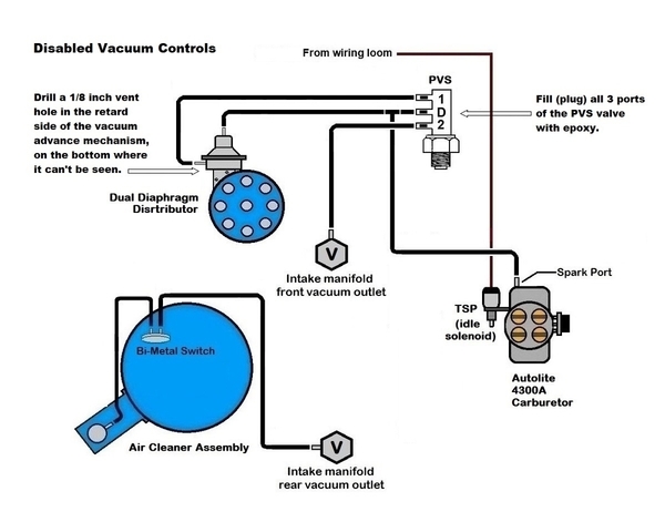
Breakerless Electronic Ignition
Ford's Duraspark breakerless electronic ignition has been suggested in the emendations above.
351C 2V engines destined for California in 1974 were equipped with breakerless ignitions. US Ford went breakerless “fleet wide” in 1975; the Australian 351C 4V (T code) was equipped with a Bosch breakerless ignition beginning 1976.
Immediately noticeable upon installation of a breakerless ignition, the engine starts quicker, runs smoother, and has better low rpm power. Power improves at all engine speeds. The ignition is an improvement over any breaker point ignition, including a dual point ignition. There are no points to adjust, thus maintenance is reduced. The Ford ignition is also more reliable than any aftermarket ignition.
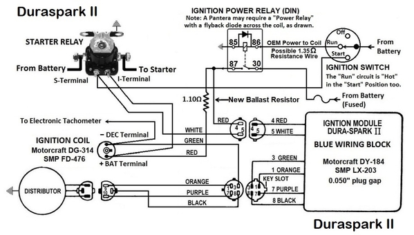
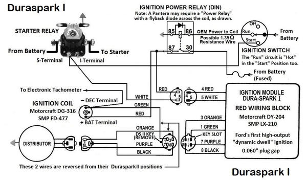
There are two Ford ignitions to choose from, Duraspark I or Duraspark II. Duraspark II is a "fixed-dwell" ignition designed to deliver a hotter and fatter spark across a wider (0.050 inch) plug gap. Duraspark II ignitions can reliably ignite air/fuel mixtures that breaker point ignitions have difficulty igniting. Duraspark I is a "dynamic-dwell" ignition designed to deliver even more spark energy across an even wider plug gap (0.060 inch). Duraspark I ignitions can reliably ignite air/fuel mixtures that Duraspark II ignitions have difficulty igniting.
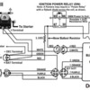
Updating a breaker point ignition to Ford’s breakerless Duraspark II ignition is a simple plug and play operation thanks to the availability of an aftermarket wiring harness: Painless Wiring # 30812. A Duraspark I wiring harness is not available, but the Duraspark II harness and the Duraspark I coil can be modified so everything plugs together properly. The Duraspark I ignition is the better ignition and worth the extra effort to install it.
Modifying a Duraspark II wiring harness for Duraspark I applications
• Swap the positions of the orange and green wires at the 4 pin connector.
• Remove the Duraspark II “key tab” from the 4 pin connector. A razor blade or box cutter work well for this job.
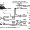
• Do not utilize any ballast resistors or resistance wire. The ignition module and coil need a full 12 volt supply. I suggest installing an "ignition power relay" to take the original wiring harness out of the picture.
• Modify the Duraspark I coil tower to allow the Duraspark II “horse shoe connector” to slip-on the Duraspark I coil. When you try to slip the connector on the coil it will be obvious which “tab” needs to be removed. A Dremel tool works well for this job.
Ignition Timing
The Duraspark distributor will need to be calibrated prior to installation.
This "street-performance" distributor curve was based upon the instructions included within Autolite's dual point distributor kit # D1AZ-12A132-A351C. This curve was also outlined in Autolite publication # MP-1046. It was (and still is) applicable to engines equipped with factory heads and flat top or dish top pistons.
• 16° to 18° initial advance.
• 20° centrifugal advance spanning 1800 rpm.
• 38° to 40° maximum recommended total advance.
• Centrifugal advance begins at 1000 rpm to 1200 rpm.
• 20° centrifugal advance all-in at 2800 rpm to 3000 rpm.
• 20° advance requires a 10L sleeve & plate assembly, or 0.410-inch slot width
• Connect the vacuum advance to ported vacuum.
• Leave the vacuum retard open to atmosphere.
Timing Set
A camshaft timing set with a 9-keyway crank sprocket is required to advance the camshaft timing as previously suggested. It is also an asset in accurately timing any camshaft.
Choosing a "good" timing set has become a challenge in the 21st century. The timing set should feature a steel cam sprocket (no nylon teeth) and a chain manufactured by Renolds or JWIS; avoid Rolon chain. It should also have a raised center needed for a two-piece (inner/outer) fuel pump eccentric, and the cam sprocket should have slots or holes to allow spray lubrication from behind the cam sprocket to reach the fuel pump eccentric on the front of the cam sprocket. Two possible candidates include Ford Racing # M-6268-A351, or Rollmaster # CS3091.
Q Code (Cobra Jet) Camshaft
The M code camshaft had 268° intake duration, and the Q code camshaft had 270° intake duration, the difference was negligible. The 40 HP difference in power between the M code engines and the Q code engines was due to valve lift; the M code camshaft opened the intake valves 0.427-inch whereas the Q code cam opened the intake valves 0.481-inch.
The M code engines were equipped with the same valve springs, retainers, locks, and rocker arm fulcrums as the Q code engines. Thus, it's easy to equip M code engines with Q code cams. Aftermarket versions of the Q code camshaft are available from Melling # SYB-29, Sealed Power # CS-650 and Manley # MS700. Replacement tappets and a new timing set with a multi-indexed crank sprocket will also be needed.
The M code/Q code valve spring had an installed height of 1.82-inches. The nominal seated spring force was 90 lbs. when installed at that height. The spring’s max lift was 0.505 inch when installed at that height. The nominal spring rate was 390 lbs/in. The spring force with the cobra jet camshaft was 277 pounds at 0.481 lift.
A substitute valve spring from Manley Performance is their Street Master valve spring # 22408-16 which is a double spring plus damper, 1.437 inches diameter. The nominal seated spring force is 107 lbs. when installed at a height of 1.82 inch. The spring’s max lift is 0.620 inch when installed at that height. The nominal spring rate is 392 lbs/in. The spring force with the cobra jet camshaft is 295 pounds at 0.481 lift.
Other parts:
Manley # 23645-16 Valve Spring Retainer, chromoly, 7°, 28 grams.
Manley # 42126-16 Valve Spring Cup.
Manley # 41836 Cutter, for Spring Cup Installation.
Sealed Power # VK-205R Valve Locks, hardened steel, 7°, for four bead stems.
Manley # 13091-16 Valve Locks, machined steel, 7°, for single groove stems.
The M code/Q code rocker arm fulcrums were made of steel (sintered iron) whereas 2V rocker arm fulcrums were made of aluminum. Be cautious not to mix 2V fulcrums with M code/Q code valvetrain. The M code/Q code fulcrums are available from Melling (# MRM-1776) or Sealed Power (# MR-1811).
SECTION 3: Durability
Roller Camshaft
Engines as far back as the 1800s utilized cam followers (aka tappets or lifters) with rollers instead of flat faces because in the days before pressurized lubrication and/or advanced oil refining technology the roller followers survived splash lubrication better than the flat faced followers. Harley Davidson V-Twin motorcycles have had roller tappets since the first knucklehead engine was introduced in 1936.
The anti-friction additive ZDDP was responsible for the longevity of the flat faced tappets in “modern era” engines. But ZDDP was slowly phased-out of motor oil because it “poisoned” catalytic converters. Thus, US Ford equipped the 302 V8 with a hydraulic roller cam in 1985. An investment in a hydraulic roller cam upgrade is an investment in the longevity of the engine, because lobe and tappet wear are eliminated. The parts are readily available, and the installation is straight forward.
If you'd like to upgrade your car's engine to a hydraulic roller camshaft without "hot rodding" it, here's a camshaft spec which is a one for one replacement for the Q code (Cobra Jet) cam. The tappets, valve springs, retainers, locks, push rods and distributor gear must be upgraded too.
Q code replica hydraulic roller cam specs:
270°/291° @ 0.006
214°/234° @ 0.050
0.480”/0.481” Gross Lift
50.5° Overlap
Ordering info for Bullet Racing Cams:
"A hydraulic roller cam for a 351 Cleveland; a one for one replacement for the factory Cobra Jet camshaft. Use lobe pattern # HR270/2775 for the intake lobes and lobe pattern # HR291/278 for the exhaust lobes. 115° LSA."
Instruct Bullet Racing Cams to index the cam one of two ways:
(1) "Straight-up; 115° ATDC intake centerline, 115° BTDC exhaust centerline".
(2) "Advanced by 4°; 111° ATDC intake centerline, 119° BTDC exh. centerline".
Indexed "straight-up" the valve events shall be:
EVO = 80.5° BBDC
IVO = 20° BTDC
EVC = 30.5° BTDC
IVC = 70° ABDC.
Indexed "advanced by 4°" the valve events shall be:
EVO = 84.5° BBDC
IVO = 24° BTDC
EVC = 26.5° BTDC
IVC = 66° ABDC.
If the cam is being ground for an engine that "must look stock" have it indexed "straight-up". The goal in that application is for the intake valve to close at 70° ABDC, the same as the M code camshaft.
Hydraulic Roller Cam Valve Train
No long explanations, just a shopping list.
Hydraulic Roller Tappets:
Johnson Lifters # 2212SBR tappets are not sold directly to the public. Purchase them from Isky Cams # 3860HYRT or from Crower Cams # 66337-16.
Steel Distributor Gear:
MSD # 85813, Mallory # 29420, FAST # 52971-1 (Crane’s former part number), or Howards Cams # 94444.
Valve Springs:
Manley NexTek valve spring # 221432-16.
• Spring OD is 1.53 inch.
• Installed height is 1.90 inches (0.080 inch taller than stock).
• Seated spring force is 150 lbs. when installed at 1.90 inches.
• Max lift is 0.630 inch when installed at 1.90 inches.
• Spring rate is 435 lbs/in.
ID Valve Spring Locators:
Manley # 42426-16 (0.062-inch thick)
Spring Pedestal Cutter:
Manley # 41856 (for 42426 locators).
10° Valve Spring Retainers:
a. Manley # 23644-16, standard (non-offset). (Titanium, 17 grams).
b. Manley # 23650-16, +0.100-inch offset. (Titanium, 18 grams).
Valve Locks for 10° valve spring retainers:
a. Summit Racing # CCA-624-16 hardened steel 4 bead 10° locks. For valves having OEM style 11/32-inch diameter 4 groove stems using aftermarket 10° retainers. Manufactured by Comp Cams.
b. Manley #13194-16 heat treated machined steel single tang 10° locks. For valves having 11/32-inch diameter single groove stems using aftermarket 10° retainers.
Push Rods:
Order them made of seamless chromoly tubing; a business specializing in push rods is Smith Bros. Push Rods of Redmond Oregon.
a. 5/16-inch OD x 0.116-inch wall.
b. 3/8-inch OD x 0.083-inch wall.
Rocker Arms:
a. At 0.480-inch lift, the factory rocker arms are perfectly fine in this application, roller rocker arms are not necessary. Rocker arm choice is a matter of personal preference. However, the factory spring force with the original (hydraulic flat tappet) cobra jet camshaft was 277 pounds at 0.481 lift. The spring force at 0.480 lift with the NexTek valve spring shall be 359 pounds. If the factory rocker arms are utilized, then install them with ARP 5/16-inch chromoly bolts # 641-1500. If the bolts are too long, then shorten them or use 1/8-inch-thick ARP washers # 200-8587.
b. Roller rocker arms for (stock) slotted rocker arm pedestals (5/16-inch fasteners): Scorpion # 3224 rocker arms or Yella Terra # YT6015 rocker arms. The rocker arms handle up to 0.650-inch lift, but the 5/16-inch fasteners limit max spring force to 420 lbs.
c. Roller rocker arms for rocker arm pedestals machined for studs and guide plates (7/16-inch fasteners): Yella Terra # YT6321 rocker arms or T&D Machine Products # 7205 rocker arms. The T&D rockers are shaft mounted, pressure lubricated, and available optionally with steel rocker bodies for the ultimate in longevity.
Lubrication is the First Durability Issue
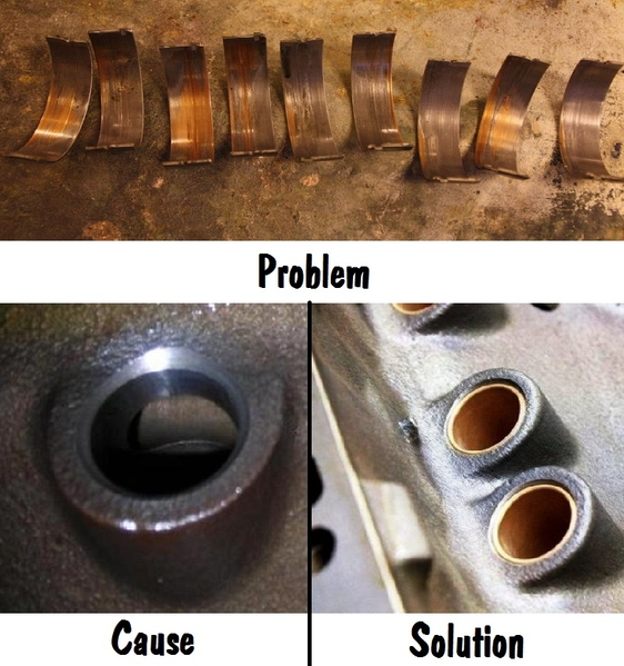
The engine's most prevalent “recurring failure mode” is excessive wear and damage to the con-rod bearings due to under-lubrication. This problem is the result of two engineering issues:
• The intersection of the main oil passages with the tappet bores creates excessively large ports in the walls of the tappet bores. This issue also manifests as low hot-oil pressure, which should be at least 50 psi at 2000 rpm.
• The routing of the oil passages drilled within the factory crankshaft inhibits lubrication of the rod bearings to some degree. The bearings for connecting rods 2 and 7 are always damaged first, or the worst.
Take steps to correct the first issue and improve the second issue while the engine is disassembled:
• Install 16 tappet bore bushings (with 0.062-inch orifices)
• Install heavy-duty, fully grooved main bearings; Clevite # MS1010HG or # MS1010VG. If fully grooved bearings (G suffix) aren’t available, improvise by using the upper shells from two sets of standard Clevite # MS1010 main bearings.
• Install heavy-duty rod bearings; Clevite # CB927.
• Set the bearing clearances and rod side clearances to promote lubrication:
a. Main bearing clearance = 0.0025 inch to 0.0032 inch
b. Connecting rod bearing clearance = 0.0022 inch to 0.0028 inch
c. Connecting rod side clearance = 0.018 inch to 0.022 inch
The emendations above were (and still are) essential. To neglect performing them is ill-advised. A reasonably priced, do-it-yourself tappet bore bushing installation kit is available from Wydendorf Machine. 269-565-5342.
Chamfer the oil holes at the crankshaft journals.
To maximize the lubrication of the rod bearings low viscosity motor oil rated 10W30, 10W40, or 15W40 should be used. But, to promote a persistent oil wedge at the rod bearings, and to avoid any problems arising from the use of fully grooved main bearings, oil viscosity lower than 10W30 is not recommended. Valvoline VR1 10W30 synthetic motor oil provides good results and has an excellent reputation.
The oil pump cannot provide an uninterrupted supply of oil to the engine unless the oil pump pick-up is constantly submerged in a bath of non-aerated oil. The Q code (and R code) engines were equipped with a standard capacity production oil pan modified by spot welding a sheet steel windage tray inside. These engines were also equipped with a higher capacity oil pump pick-up.
That level of functionality can be duplicated for M code engines with an aftermarket windage tray from Milodon (# 32220) or Moroso (# 22939) and an aftermarket version of the higher capacity oil pump pick-up from Melling (# M84-AS1), Milodon (# 18635), or Sealed Power (# 224-11166).
However, a wet sump racing style oil pan should be chosen if a car shall be subjected to high g-force maneuvers (acceleration, cornering, braking). The oil pan should have 7-to-10-quarts capacity and should feature a windage tray, a scraper, and hinged door baffles. A racing oil pan will also have its own specific oil pump pick-up.
Durability Issues Beyond Lubrication
Threads stripped out of connecting rod nuts are another “recurring failure mode” common to the 351C. This problem is easy enough to correct; replace the failure prone nuts with ARP # 300-8381 nuts.
The factory valves have a nasty reputation, at least in the US. The valve heads break-off their valve stems from time to time and wreak havoc on the engine. This is a third “recurring failure mode”. This problem is corrected by replacing the factory valves. Cylinder head reconditioning is an opportune time to replace the factory valves for peace of mind.
If the valves are being replaced, then do not replace them with OEM (Ford) valves! Use high quality steel aftermarket valves. Stainless steel valves which are lighter in weight and swirl polished should be considered as a performance option. Light weight and swirl polished valves usually have single groove stems as well. One possible choice (among many) for stainless steel valves are the valves from Manley Performance:
• Manley # 11872-8 2.19-inch Race Master intake valve, 129 grams.
• Manley # 11800-8 2.19-inch Severe Duty intake valve, 139 grams.
The factory intake valve weighed 147 grams.
• Manley # 11873-8 1.71-inch Race Master exhaust valve, 104 grams.
• Manley # 11805-8 1.71-inch Severe Duty exhaust valve, 108 grams.
The factory exhaust valve weighed 123 grams.
To complement those new valves, install bronze valve guides in the cylinder heads, and have 3 angle valve seats ground.
The valve stem to valve guide clearance should be 0.0007 inch to 0.0018 inch (0.0012-inch nominal) for the intake valves and 0.0011 inch to 0.0022 inch (0.0016-inch nominal) for the exhaust valves. Reaming all the valve guides for 0.0014-inch clearance is one strategy.
The valve seat angles should be cut at 45°, the seats should be blended into the valve pockets at 70° (as per Ford) and the seats should be blended into the combustion chambers at 30°. The width of the intake seats should be no less than 0.060 inch; the width of the exhaust seats should be no less than 0.080 inch. Valve seat run-out should be 0.0010 inch or less.
The OEM rod bolts have a tensile strength of 150,000 psi and are rated for 45 ft./lbs torque. Stronger rod bolts are another performance option. Chrome moly rod bolts, like the 351 Boss rod bolts, have a tensile strength of 180,000 psi and are rated for 50 ft./lbs torque. ARP sells two chrome moly rod bolt kits: kit # 154-6003 (knurled shanks) and kit # 154-6403 (wave-loc shanks). For the ultimate in strength and clamping force another ARP “wave-loc” rod bolt kit, # 254-6403, is manufactured using their proprietary ARP2000 metal. Those rod bolts have a tensile strength of 220,000 psi and are rated for 55 ft./lbs torque.
Whenever the rod bolts are replaced, the connecting rod big ends must be resized.
If the flywheel’s assembled clutch face run-out is 0.010 inch or less, if it has the typical grooves and ridges but can be cleaned up by removal of no more than 0.045-inch material, then a simple resurfacing may suffice. However, if the flywheel shows signs of stress cracking or heat checking, if it would require the removal of more than 0.045-inch material to clean it up, if it is warped or has excessive clutch face run-out, then the flywheel should be replaced.
A lighter flywheel is the performance-oriented choice when it needs replacement. An aluminum flywheel is one option, the durability of a lightened steel flywheel is another option. At 26.4 pounds the Yella Terra flywheel # YT9902 is the lightest billet steel flywheel available. The Yella Terra flywheel is drilled for long style pressure plates like the OEM factory pressure plate.
The rubber sleeve of a 20 year old damper, hardened by age and heat cycling, no longer dampens as designed. The hardened rubber also allows un-bonded outer rings to “walk” on the hub; thus the timing marks are most likely incorrect. Any crankshaft damper over 20 years old is over-due for replacement. Replace it with PowerBond's "fully bonded" damper # PB1082SS.
An unbalanced or incorrectly balanced reciprocating assembly can become the source of the following problems:
• Rings that won’t seal properly.
• Ring failure.
• Piston skirt failure.
• Damaged cylinder walls.
• Accelerated wear of the crankshaft bearings.
• Crankshaft damper deterioration, performance issues, and failure.
• Ignition performance issues.
• Oil pump chatter and performance issues.
• Accelerated wear and stretching of the camshaft timing chain.
• Valve train instability.
• Valve spring failure.
• Front pump failure in automatic transmissions.
• Pressure plate and clutch spring failure in manual transmissions.
Consequently, balancing the reciprocating assembly is very important. Spin balancing, also known as dynamic balancing, is better than static balancing, and should be performed if a high-performance engine is being built. Spin balancing reduces the destructive forces which are felt as vibration and harshness; thus improving durability and making the engine smoother operating and more inviting (or less dramatic) to operate at higher rpm.
If the cylinders have been over-bored, then new pistons shall be required. If it is also planned to have the reciprocating assembly balanced, then do those thin cylinder walls a favor. Select Ross # 80556 round skirt flat top pistons as the replacement pistons. Custom order them with compression heights of 1.650 inches. They are lighter in weight (537 grams), their full round skirts spread thrust loads over broader portions of the cylinder walls, and they minimize piston rocking. Thus, the Ross pistons reduce the forces which crack the cylinder walls.
Upshot
In summary, these M code and Q code versions of the 351C had the same size intake ports and intake valves as Ford's 427 medium riser NASCAR engine. They "pulled harder" than most engines at high rpms. They also produced an additional 30 ft/lbs of torque compared to rival 350 cubic inch engines by virtue of their combustion chamber design. Emended (de-smogged) as suggested above, they are very strong performers which also possess good drivability and low-end torque, suitable for daily driver usage. To repeat the opening premise, the difference between a car powered by a 280 horsepower 351 Cobra Jet having 8.0:1 compression and a car powered by a 350 horsepower 351 Cobra Jet having 10:1 compression is startling!
-G


