In the process of installing an LCD mirror and backup camera I've managed to lose two of the tiny nuts that hold the reverse light wires in place. Can any of you tell me their size or a source.


FYI, if you plan on buying an electronic rear view mirror system, buy one that comes with useful instructions. I bought a system from Master Tailgaters and it has virtually no useful instructions, and what is included was obviously written by a Chinese. It looks like its plug and play, but it's not. For example, the wiring harness has what's called trigger wires in several places. These wires protrude about six inches from the RCA plugs. It tells you absolutely nothing about them, what their purpose is and how to engage them.  The system can apparently work with or without their use.

Original Post

Replies sorted oldest to newest

Some of the '72 cars had the +12v for the backup lights connected to fuse 3, which is one of the parking light fuses.  That required the parking or headlights to be on in order for the backup lights to work.

Most of the cars had the +12v for the backup lights connected to fuse 12.

If your backup lights only work when the parking or headlights are on, find fuse 3 and look for a small gauge green wire that is connected to fuse 3. Disconnect that wire and verify that the backup lights no longer work. Connect that wire to fuse 12. Any spare terminal on fuse 10, 11, or 12 will work.

John

First about backup lights in general. It was determined that backup lights were originally invented for the tanks of the Italian army. I don't know if this is true, but this forum will likely include a military historian who can shed light (ha ha) on this matter.

As for the alternate wiring for the backup lights, that's worth a go.

Thank you,

Tom

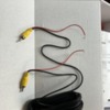
The Master Tailgater rearview mirror system that I bought is quite short on directions and so far the results have been less than impressive. Thinking it's the fault of the camera, I placed an order for a better one which should arrive shortly. The biggest unanswered puzzle are the trigger wires that appear on the wiring harness and both ends of the extension wire connecting the rear mounted camera to the mirror connection near the front (under the dash). See attached photo of a 12 foot extension cable that comes with the system. It has a 6 inch long red trigger at both ends. Do any of you know how to connect them, and to what?

Attachments

Images (1)
  • trigger wire

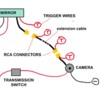
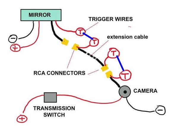
I guess I'm still not smart enough to understand the trigger wires. The attached diagram is my understanding of the situation. Why is there a trigger wire at each end of the extension cable? do they connect within the cable? What do they need to connect to?

The mirror and the camera each have trigger wires and power supply capability,

Attachments

Images (1)
  • mirror diagram by tom

Your question has already been answered. To perhaps better explain, you connect the red wire to a wire going to your back up lights. This will send 12 V through the red wire to your dashboard area where, as previously explained, the 12 V will tell your device to activate the video screen circuit.

I too was a bit confused when hooking up my back up camera to my Kenwood. Once it all goes together, you will realize it really is quite simple

Larry

To spell it out even more... it's confusing that red wires appear to exit the connectors - they don't... it's just easier to make the cable that way. There are 3 wires in total in that cable:

1- video signal - between the centre of each connector.

2- video ground - between the outer ring of each connector.

3- a red wire - each end sticks out near the connectors.

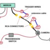
Tom,  Here is what I see you need to do.

1. The camera needs power to operate and it will get its power from the Transmission Switch when you put your car in reverse.

2. The Mirror also needs power to operate hand gets it power from the separate + & - wires in your diagram.

3. Now you need to tell the mirror to tun on, so you need to connect the triggers wires together at each point so the mirro know to turn on.  See my diagram with the blue lines.  I am assuming the trigger wires send ground to the mirror to activate it.  The red wires I think are connected to the ground of the cable for the camera.

You can PM me if you need some more help.Back Up Camera

Attachments

Images (1)
  • Back Up Camera

The wires at the back up switch are a constant hot and a switched hot. You can confirm this by studying the SOBill diagram posted early in this thread

The red trigger wires do not carry a ground, they carry a +12 V.

It is best to tap into the back up light wiring in the tail light bucket area to make sure you are getting the switched tail light power, not the constant 12 V hot that goes to the switch.

Larry

Last edited by lf-tp2511

Add Reply

Post
×
×
×
×
Link copied to your clipboard.
×