

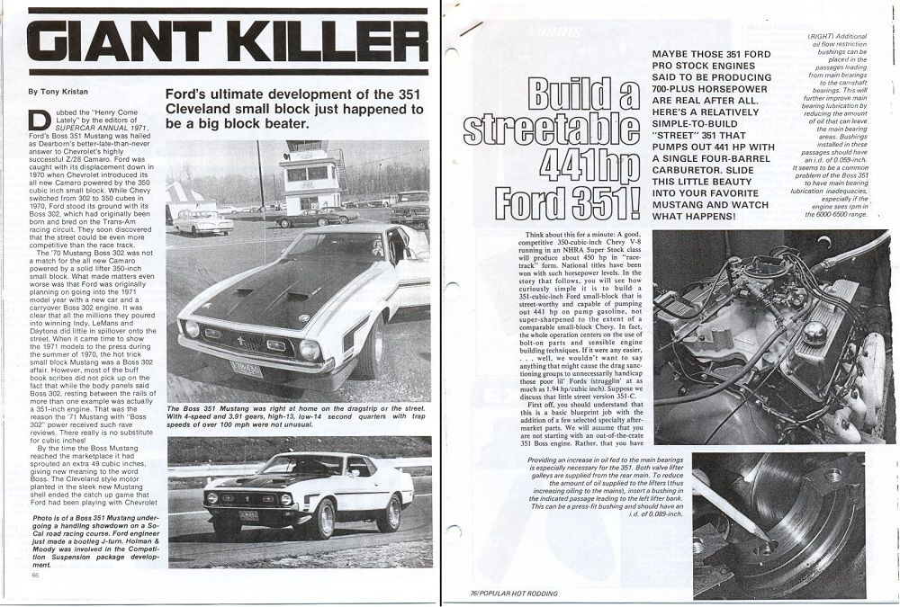
The 351C became the darling of the performance industry from 1970 to 1973, nothing negative was written about the 351C during those years, there was no commentary about the intake ports being too large. Instead there were numerous magazine articles written extoling the engineering built into the motor, articles about 400 to 450 horsepower street build ups, and other articles about 515 horsepower or more race build-ups. Hardly a couple of months would go by without a new article about the 351C appearing in a magazine. The 351C had earned a reputation as a formidable racing engine and a big-block trouncing street performer by the time Ford abandoned high performance and racing in February 1973. The Arab oil embargo of 1974 changed everything however. The focus of the aftermarket industry shifted to parts geared towards fuel economy; parts such as small tube headers, small runner intake manifolds and economy or RV camshafts. In this climate the 351C fell into obscurity just as easily as it had risen in the limelight only a few years earlier, 351C magazine articles became scarce. While there were many people and companies having a vested interest in maintaining the popularity of the small block Chevy, few if any people or companies had a similar interest in maintaining the popularity of the 351 Cleveland; even the Ford Motor Company had abandoned promotion of the 351C. If you were into Ford performance cars during the Cleveland's glory years or if you were a fan of a Cleveland powered automobile you likely continued to admire the Cleveland even after the oil embargo; auto enthusiasts in general however slowly forgot about the 351C or adopted a negative attitude towards it. I was one of those people who remained a Cleveland enthusiast due to my passion for the DeTomaso Pantera and my involvement with Mustangs.
There was a preference amongst Ford enthusiasts to use Ford parts, especially when it came to parts for the motor. In contrast, the Chevy guys relied heavily upon aftermarket parts. Ford enthusiasts considered aftermarket parts poorly engineered, poorly manufactured, poorly fitting and prone to early failure. The prevalent attitude was there should be a tangible benefit in power output or durability to justify parts replacement. Replacing factory parts to look "racy" was frowned upon, parts changing was to be kept to a minimum, guys who replaced too many parts were considered uninformed. Keep in mind as I mention the parts I liked to use that none of those parts were difficult to find in the 1970s as they would be today, they were all readily available in wrecking yards or over the counter from a Ford parts department or a Ford Speed Shop.
Ford had big plans for the 351C but those plans were interrupted by constantly changing tailpipe emissions regulations. Ford never produced a version of the 351C we considered the definitive street version so we assembled our own "ultimate" 351C street engines using a conglomeration of parts from the M code, R code and Q code motors. Most of those parts could be sourced from the 1971/1972 Q code motor which provided a short block having flat top pistons, 4 bolt main bearing caps, the good windage tray equipped oil pan, the good oil pump pick-up, a dual point distributor, a 750 cfm Motorcraft 4300D carburetor and the good non-EGR spread bore intake manifold. Added to those Q code parts were a 1971/1972 R code (Boss 351) crankshaft damper and 1970/1971 M code quench chamber heads.
351C ignition options evolved during the 1970s. Prior to the introduction of Ford's breakerless ignition systems there were two choices for a 351C performance ignition using Ford parts. The first choice was the factory dual point distributor with vacuum advance; it was good to 6000 rpm but the centrifugal advance needed to be recalibrated for best performance. The second choice was any 351C distributor upgraded with Ford’s dual point kit #D1AZ-12A132-A. The kit included a point plate equipped with high rpm dual points and springs for recalibrating the centrifugal advance for 20° of advance by 2800 rpm. To achieve that curve the kit had to be used in conjunction with a 10 degree distributor cam #C5AZ-12210-B (stamped 10L). Ford recommended 16° of initial advance but also stated that 38° to 40° of total advance was the maximum recommended. This was the ignition curve we used in our motors. The dual point kit turned a single point distributor which was only good to 5000 rpm into a centrifugal advance only dual point distributor good up to 7000 rpm. A recalibrated factory dual point distributor was preferred for hydraulic cam street motors over a distributor converted with the D1AZ-12A132-A kit because the lower spring tension of the 6000 rpm points prevented the points from going out of adjustment as quickly and the vacuum advance improved fuel economy. The higher rpm capabilities of a solid lifter street motor however required using a centrifugal advance only distributor with the 7000 rpm points.
Ford distributors are admittedly not very good, and a lot of Ford racers seemed to have a preference for Accel ignition parts; for example Accel distributors with Ford part numbers were amongst Ford’s “secret inventory” of racing parts. There were a lot of Accel and Mallory dual point distributors installed during the 1970s because they were less expensive than the "electronic" ignitions; like all new technology "electronic" ignitions were over-priced and unreliable. The problem with the race ready high rpm dual point distributors was the points used very stiff springs and therefore they wore quickly and went out of adjustment quickly. Constantly adjusting points in a daily transportation street car was a pain in the arse, so we experimented with the options in breakerless ignitions as they came on the market in the 1970s. A couple of options that come to mind are the Hays Stinger and the Ford #DZ-5003 retrofit kit.
Ford introduced their breakerless ignition in 1974 and it became standard equipment across their entire model line in 1975. We began using Ford breakerless ignitions to upgrade our older performance cars as soon as donor cars began showing up in the wrecking yards, but this took 4 or 5 years. The Ford ignitions were RELIABLE! The aftermarket "electronic" ignitions in that era were all considered unreliable to one degree or another.
Most aftermarket and OEM electronic ignitions controlled charging of the coil with a ballast resistance and dwell time, which varied in proportion to engine speed. This was no more elaborate than a breaker point ignition, but the electronic ignitions produced a more potent spark because they were beefed-up to handle more current and were used in conjunction with coils having lower primary resistance.
California was the only state in which Ford vehicles were equipped with 1977--1979 Duraspark I ignition modules (the module with a red wiring strain relief); the rest of North America was not familiar with this module. Amongst the various ignition modules Ford manufactured the Duraspark I module was the only module that didn’t charge the coil in the conventional way, the Duraspark I utilized dynamic dwell, no ballast resistance and a coil with a very low primary resistance. The Duraspark I produced a very potent spark and constantly adjusted dwell to prevent over charging or under charging the coil. The Duraspark I was truly one of the best ignition modules available anywhere, but it didn't have all the features we wanted like ignition retard during starting and rev limiting. The 1979--1980 Duraspark II module with a white wiring strain relief featured ignition retard during starting, so this was the preferred module for high compression motors that had trouble cranking when they were hot. Ford Motorsport sold a Duraspark II module (#M-12199-A301) that had built-in rev limiting. When it came to Ford ignition modules you had to compromise and decide which feature was most important for your application because you couldn’t have all 3 in one module. By the end of the 1970s we had settled on Ford's 1977--1979 Duraspark I breakerless ignition as the best choice for a high performance street motor, especially one that had to pass tailpipe emissions testing.
The M code (D0AE, D1AE) quench chamber heads were updated with a few Boss 351 parts: the Boss 351 valve springs #D0ZZ-6513-A, the Boss 351 spring seats #D0OZ-6A536-A, and the Boss 351 spring retainers #C9ZZ-6514-A; the Boss springs were rated at 92 pounds with the valve on the seat (installed height = 1.82”) and 315 pounds with the valve open ½ inch (spring rate = 446 pounds per inch). The failure prone factory valves were replaced with Manley single groove stainless steel valves and Manley locks. In the mid-1970s I could walk into a NAPA auto parts store and order the Boss 351 parts!
There was a compression ratio “fear-factor” in that era to contend with, unleaded pump gas was a new thing, the magazines recommended 9.0:1 compression ratio for street motors back then, and enthusiasts were fearsome 10.0:1 compression ratio motors would ping when burning the new gas. Ford didn’t help alleviate people’s concerns by rating the M code motors one whole point higher in compression than they really were; the 1970 motor was rated at 11.0:1 compression ratio even though its compression was actually 10.0:1, the 1971 motor was rated at 10.7:1 compression ratio even though its compression was actually 9.7:1. People are quite often reluctant to believe Ford over-rated the compression ratio of those motors by that amount.
A conservative 9.0:1 compression ratio may have been a good recommendation for a small block Chevy in 1974, but we never had a problem with our Cleveland motors pinging at 10.0:1 compression which was our usual compression ratio goal for a hydraulic camshaft 351C 4V street motor, especially if it had cast pistons inside. We often had the heads milled down to achieve 63cc combustion chambers, depending upon what the motor’s deck clearance looked like. We were milling quench chamber heads when everyone else was going the opposite direction! A standard displacement 351C with 63 cc combustion chambers and 0.075” total clearance (0.040” head gaskets plus 0.035” nominal deck clearance) has 10.0:1 compression ratio. Since we often used the short block “as-is” and therefore the decks were not leveled, we didn’t want to push the compression ratio to the limit; 10.0:1 compression was actually a safe setting even though it was considered “radical” by others.
The valve train utilized an over-the-counter Ford hydraulic camshaft, part number D1ZZ-6250-BX, which was a very popular street cam in its day. It was a hydraulic version of the Boss 351 camshaft, a perfect street camshaft from the perspective of maintenance and powerband; it increased the motor’s output by about 20 horsepower over the output attained with the Cobra Jet camshaft, about 50 horsepower over the output attained with the M code camshaft. Almost every cam grinder and hi-performance parts vendor offered a version of this cam in their catalog. It’s still available today as Speed Pro #CS173R or Melling #24224. The cam specs were:
290°/290° duration @ 0.004"
0.505"/0.505" lift
Exhaust valve opens at 84° BBDC
Intake valve closes at 74° ABDC
62° overlap
219°/219° duration @ 0.050"
114° lobe separation angle
Intake lobe centerline = 109° ATDC
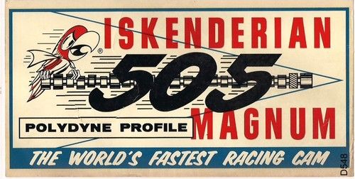
A half inch of valve lift was a lot of lift for a hydraulic lifter street cam in the 1970s! I believe the 0.505” valve lift of this cam was an intentional marketing ploy because Iskenderian Cams manufactured famous and successful camshafts in the 1960s with the number 505 in the name; such as the “505 Magnum” camshaft and the “505 Race Master” camshaft. Copyright infringement may explain why Ford never advertised this camshaft’s existence. The cam was listed in the Shelby catalog, but the valve lift specification was listed as 0.498” instead of 0.505”.
We didn't like push rod guided valve train, so we utilized the factory steel rocker arms as long as the valve spring force at maximum lift didn’t exceed 350 pounds; the D1ZZ-BX cam used in conjunction with Boss 351 springs didn’t warrant roller rockers. When the Crane Cams roller fulcrum kit was introduced we started using it too (#36806-16). If the Crane roller fulcrums had used 7/16" fasteners instead of 5/16" fasteners they would have been perfect. Ford’s stamped steel rocker arm is an excellent part, the 5/16” fasteners have always been the limiting factor of the factory pedestal mount rocker arm design. We preferred heavy wall 5/16" push rods over 3/8" push rods because there were no clearance issues. Ford sold the good lifters over the counter (hydraulic D1AZ-6500-B, solid D1ZZ-6500-B). We weren't too picky about the timing chain, as long as it had steel teeth for the cam gear and a multi-index crankshaft gear it was OK.
That’s the basic parts list for an “ultimate” 351C street engine. A 351C consisting of those parts ran smoothly (i.e. "stumble-free") throughout its powerband like a factory motor; with 1-7/8" or 2" headers (Hooker, Doug Thorley or Hedman) and a good exhaust system (Cadillac mufflers) it produced 350 to 390 horsepower depending upon how much money we put into preparing the motor and into upgrades. It was stronger than a showroom stock Boss 351; it possessed good low rpm torque thanks to the quench heads, it came on the cam with brutish acceleration and it didn't run out of steam at high rpm. Thus modified it was still capable of passing emissions testing too. With dynamic balancing the motor had a very smooth running, high quality feel to it, equal in smoothness and powerband to expensive exotic European motors equipped with Webers. If this sounds impressive it was. It was an awesome engine for its day, and it would hold its own even today, 40 years later.
If the short block was being rebuilt we used tri-metal (Clevite 77) bearing kits that included fully grooved main bearings, we didn't ask for fully grooved main bearings, we took them for granted, the tri-metal bearing kits just came with them. The crankshaft would be ground with larger than stock clearances; the popular rod bearing clearance was 0.0025” to 0.0030” which was the clearance recommended in the Ford OHO manual. The popular main bearing clearance was 0.0020” to 0.0025” which was a little less than the clearance recommended in the Ford OHO manual; this clearance was chosen to keep the hot oil pressure up and to encourage oil flow to the rod bearings. The crankshaft was also tuftrided, polished and dynamically balanced. Whenever the short block was torn down the factory connecting rod fasteners were replaced with SPS rod fasteners because we believed the production rod bolts were responsible for connecting rod big end failures that were experienced from time to time. After replacing the rod bolts the connecting rod big ends had to be resized. If we had known then, as we do today, that the rod nuts were the actual weak link we would have replaced the rod nuts in every motor because they can be replaced without a complete tear-down of the motor and without having to re-size the connecting rod big-ends. If the motor needed pistons, flat top cast pistons were available from many sources for tight budgets, or we used forged round skirt endurance racing pistons if the budget allowed. In between those two extremes were the TRW #L-2379 forged pistons; the TRW pistons did not have the desired full-round piston skirt design, but they used production sized 5/64" rings, they were compatible with pressed pin applications and the price was right. We preferred pistons with a compression height between 1.650” and 1.670”; the production compression height was 1.650”. Boring and honing the cylinders and leveling the decks were the usual extent of machine work for the hydraulic camshaft motors. If the cylinders required boring they were bored without being indexed to the crankshaft because the pistons were used with pressed pins.
Solid lifter street motors were built to rev up to 7200 rpm for short periods of time; this meant solid lifter motors were more expensive to build. Besides the work mentioned in the previous paragraph the main bearing saddles were align-honed; the cylinders were indexed to the crankshaft, bored and honed; and the decks were leveled. Cylinders which are canted front to back will thrust a floating wrist pin in a way that will hammer out the pin locks, so indexing the cylinders is a necessity prior to installing floating wrist pins. Forged endurance racing pistons were a necessity for our solid lifter motors, as was fully prepping the rods which included magnaflux inspection, smoothing the beams, shot peening, installation of bushings for floating pins, and rebalancing. The compression ratio was set at least a half point higher than the compression of the hydraulic cam motors (i.e. 10.5:1 or more). The lubrication system was set-up for high rpm by installing lifter bore bushings using a bushing installation kit sold by Ford; the kit included 8 bushings for the right hand lifter galley, a big restriction for the left hand galley and 4 small restrictions for cam bearings #2 through #5. In those days we didn't feel the lifter bore bushings were needed for hydraulic cam motors, only for solid lifter motors because of their greater high rpm potential. The heads were equipped with Boss 351 studs #C9ZZ-6A527-A, Boss 351 guide plates #C9ZZ-6A564-A, and lightweight Ford valves (the titanium intake valves #D0ZX-6507-A weighed 85 grams, and the hollow stem exhaust valves #D0ZX-6505-A weighed 95 grams). We relied on the expensive lightweight valves to give the motor its high rpm capabilities because heavy race-type valve springs would be detrimental to valve train life. The valves were actuated by Crane Gold rocker arms. The camshaft varied with each solid lifter engine project; but Vasco Jet valve springs having spring rates of about 450 pounds per inch were the preferred valve springs. The Vasco Jet springs were racing springs with a reputation for durability. The externally balanced crankshaft and the relatively light weight street valve springs were the only ways a solid lifter street motor such as this differed from a race motor. Solid lifter street motors built to this spec, producing 440 to 500 horsepower and operated with a rev limit of 7200 rpm were durable motors.
The Pro stock Pinto book was adamant that 50 psi was the minimum allowable hot oil pressure for a Pro Stock motor; we applied that limit to street motors too. We didn’t think it was wise to run the hot oil pressure on the ragged edge of the safe oil pressure limit either, so we relied on the 10 psi per 1000 rpm rule and made 60 to 70 psi the target hot oil pressure for our 351C street motors. Our target hot oil pressure was validated in the 1990s by Don Nicholson who was quoted in print stating 60 psi hot oil pressure that holds steady until the rev-limit was enough pressure even for Pro-Stock racing. Sixty psi could be difficult to achieve with factory components however after the crankshaft bearing clearances had been increased. There were three schools of thought regarding modifying the 351C lubrication system for hydraulic camshaft street motors:
(1) One school of thought preferred no modifications at all. Achieving 60 psi hot oil pressure with no modifications was possible only if the bearing clearances were within the range of the “desired” factory specification which was 0.0010” to 0.0015” main bearing clearance and 0.0011” to 0.0015” rod bearing clearance (the Ford manual listed two bearing clearance specifications, the “desired” specification and the “allowable” specification). We found however using the “desired” factory bearing clearances in a high performance motor resulted in bearing damage. I wouldn’t recommend such tight clearances even in a motor for a “grocery getter”.
(2) A second school of thought preferred following the advice given by Jack Roush in a 1976 story published in Hot Rod magazine. Jack Roush recommended a standard volume oil pump, the Moroso high pressure oil pump relief spring and the Moroso cam bearing restriction kit used in conjunction with 0.0020” to 0.0025” main bearing clearance and 0.0025” to 0.0030” rod bearing clearance. The motor’s cold start oil pressure ran about 120 psi with the high pressure oil pump relief spring installed, enough to burst an oil filter canister if the driver inadvertently blipped the throttle. A Motorcraft high pressure oil filter # FL-1HP was recommended to use in conjunction with the high pressure spring.
(3) The final school of thought preferred a high volume oil pump to deliver more oil to the crankshaft bearings ground for 0.0020” to 0.0025” main bearing clearance and 0.0025” to 0.0030” rod bearing clearance. But installation of a high volume oil pump alone without taking any measures to control where the extra oil was flowing would also supply more oil to the camshaft bearings and the valve train. So to control the oil flowing to the camshaft bearings the small restrictions from the Moroso cam bearing restriction kit were installed, and push rods having restrictions in the tips were installed to control the oil flowing to the valve train. In this way the extra oil supplied by the high volume oil pump was routed as best as possible to the crankshaft bearings where the clearances had been increased. This was the lubrication scheme Ron Miller liked to use.
Today we realize more oil is lost in the clearances between the lifter and the lifter bores than we imagined in the 1970s. There are also lifter compatibility issues today we didn’t have back then. Today my preference is installation of lifter bore bushings in all 16 lifter bores and installation of cam bearing restrictions for all 5 cam bearings; for all 351 Clevelands, in all applications. This strategy gets down to the real bottom of the problem, it converts the 351C lubrication system into a main priority design; it is the only strategy that truly insures enough lubrication is getting to the crankshaft, that insures an equal amount of oil is routed via each lifter to each rocker arm and each valve spring and that alleviates lifter compatibility issues.
One upgrade to our basic parts list was a better intake manifold and a Holley carburetor; this was worth at least 20 additional horsepower. We considered the Shelby dual plane intake manifold the best street manifold. The Shelby manifold was actually designed by Ford engineers; the Shelby parts operation was owned by Autosport Products Incorporated, which was a company owned and operated behind the scenes by Ford. The Shelby manifold is not a true high rise manifold; the design was compromised for compatibility with shakers and ram-air. Although it is a bit higher than the factory intake manifold and its carburetor pad is better centered it was still compatible with 1970 style shaker air cleaners and 1971 style ram-air. To be a true high rise manifold the lower plane would need to be raised 1-1/2 inches or more.
FYI: The Shelby manifold had a design flaw. The bolt hole located between the runners for cylinders 3 and 4 snuggles very closely against the runner for cylinder #3. That hole is unfinished as it comes out of the box, and it is impossible to get a bolt in the hole. That's why there are so many unused Shelby manifolds that come up for sale on eBay. If you use a grinder to enlarge the notch on the side of the #3 runner and use a fly cutter to spot face the bolt hole for the head of a bolt the runner becomes paper thin; in fact most people punch a hole in the runner the first time. I was one of those people. It was a good manifold however and was worth the extra effort to prep the bolt hole that the manufacturer was unwilling to prep themselves.
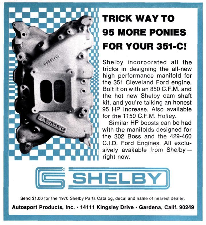
The Shelby parts business was closed down in 1974 and Shelby manifolds became hard to find during the latter half of the 1970s, we were glad when AT Francis reintroduced the manifold as the Blue Thunder manifold circa 1981. AT Francis also fixed the problem with the bolt at runner #3.
A Holley 750 cfm/780 cfm carburetor was used in conjunction with the Shelby manifold. The Ford parts counter was the source for a properly configured carburetor that was tuned for street applications and capable of passing smog testing. The three 780 CFM vacuum secondary 4150 Holley carburetors recommended by Ford for the 351C included:
D0ZZ-Z, Boss 302, manual transmission - manual choke
D0OZ-N, 429 SCJ, manual transmission - automatic choke
D0OZ-R, 429 SCJ, automatic transmission - automatic choke
Living in a state that performed smog inspections precluded heavily modifying the motor, but another performance upgrade that didn't affect the motor's smog performance was head porting and three angle valve seats, that was usually worth 15 to 20 horsepower, and I considered it "free" horsepower because it didn't impact drivability or tail pipe emissions.
You'll notice most of the stuff I've mentioned was not mentioned in the Ford Performance book by Pat Ganahl, we always thought that book kinda sucked because in several ways it was out of touch with the Cleveland scene. For example the book was published in 1979, but he quoted the 1972 Pro Stock Pinto book regarding the lubrication system, a quote which recommended the high pressure oil pump spring for solid lifter race motors. Of course, boosting oil pressure with the spring (introduced in 1972) didn't fix the lubrication system so racers continued looking for a solution. Lifter bore bushings came on the scene in 1973 and became the ultimate solution. Soon afterward Ford began selling a lifter bore bushing installation kit. In quoting the Pro Stock Pinto book regarding the lubrication system Pat Ganahl's book perpetuated old (bad) information thereby misleading 351C enthusiasts regarding the lubrication system. Another example, there's not one mention of the D1ZZ-BX camshaft or the Shelby intake manifold, yet both of these parts were highly regarded in the 1970s. He also advised against porting the 351C 4V heads for the street out of fear of making a port which was too big even bigger; which was like throwing 20 horsepower down the drain. Anyone who is informed about porting the 351C 4V intake port knows the port cross section isn’t increased that much, the port is just cleaned up, most of the work is in the bowl, the valve seats and the combustion chamber. Pat Ganahl didn't mention gearing either, but proper gearing is important for setting up a vehicle with a 351C 4V.
On the subject of gearing ... Ford never made a specific gearing recommendation for the 351C 4V but recommended 4.30:1 gearing for the Boss 302. As far as we were concerned a 351C 4V motor called for 3.89:1, 3.91:1 or 4.11:1 gears with traction lock limited slip differentials. The 1970 cars equipped with FMX automatics were usually upgraded with later model C6 transmissions, and the M code cars were upgraded to the Q code torque converters (3000 rpm stall). Transmission fluid coolers plucked from station wagons at the wrecking yard were added to all hi-stall converter equipped automatic transmissions. Another improvement using wrecking yard parts was replacement of the OEM style flex-blade radiator fan with a clutch equipped radiator fan which put a little less drag on the motor, and ran quieter too.
Shelby/Traction Master style traction bars were recommended for cars equipped with leaf spring rear suspension including models equipped by Ford with staggered rear shocks. The staggered rear shocks didn’t control axle wind-up very well, they may have been better than nothing at all, but we considered them useless. There was a downside to staggered rear shocks too, they caused the rear suspension to “crab walk” over two wheel bumps such as speed bumps. We would normally un-stagger the rear shocks after traction bars were installed, unless the owner objected. The rear suspension worked much better with the shocks un-staggered, the traction bars eliminated axle wind-up, and the rear brakes worked better too.
The 351C turned 10 years old in 1979. By the early 1980s Ron Miller’s shop was advising customers to use Ford Motorsport's new quench chamber 2V heads # M-6049-C351 for heavier cars like the Torino and Montego. Ron believed the 4V heads were best used on the street with lighter cars like the Pantera, Mustangs and Cougars; he claimed the heavy cars would accelerate faster with the small port heads. I never gave it a try however. It was in this time period that the Mustang restoration hobby took-off, Bill Elliot became a NASCAR superstar (piloting a 351C powered T-Bird), Ford Motorsport began selling high performance street parts and racing parts over the counter, 351C manufacturing in Australia was coming to an end and there was resurgence in the popularity of the Pantera in the US. The 351C remained Ford’s premier racing engine until about 1985 when it was pushed aside to make room for 351W block/canted valve head hybrid racing motors, which Ford called SVO motors.
-G