While I tagged a previous discussion regarding the topic, I realized it was in the Engine Section posting and not in the Electrical.
I am attempting to upgrade the fan relays as has been posted numerous times. My fuse panel has only one pink wire from fuse #11 to one relay and a jumper wire to the second relay. Mike Drew's write-up for this situation states to add an auxiliary fuse panel. Is this the only solution?
Original Post

Replies sorted oldest to newest

Thanks for bringing this up. I think I found the M Drew article you referanced. the modifications he recomends are to reduce the current through the ignition switch by using a auxilarry relay to provide the current to the fan, thus more than a relay upgrade.

these types of modifications to the electrical wiring is something I really wanted to work out myself (instead of given the car over for a turn key rebuild). While I can see the schematic changes needed, I don't know the physical locations and the accessabilities.

the one thing I have not seen addressed yet (maybe it has been) is to provide an alternator side distrubution block near the battery instead of having to go to the ampmeter terminals for adding accesories

If you are just going to rewire the fan circuit, what is the reason not to use a single inline fuse from the alternator for the fan power?

Attachments

Images (1)
  • fuse_11
Last edited by jfb05177
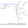
JFB; My situation is as your schematic indicates, before your changes, one pink wire carries the load for both relays. I'm concerned about the one pink wire's ability to operate both fans as well as fuse 11's capability. My fuse 11 feeds the pink wire to the two relays with a jumper wire from one relay to the other; however, fuses 11 & 12 are bridged where the red wire comes into the fuse box. I was thinking of running an add'l wire from fuse 12 (where I have an open spade) thereby having a dedicated wire to each fan relay. The posted fan wiring revision indicates fuse 12 as having the 2nd pink wire to trigger the second relay. It appears that while I have a June '72 build date, I have the earlier wiring in which one pink wire carries the load of both fans. Mike Drew's write up refers to the one pink wire for both fan to be a marginal situation.
The way I "see" the M Drew recomended wiring change is that the original fuse 11 fan load will only be the new relay coil.
the actual current for the fans will be the new wire to the relay contact AND this new relay mounted with the original fan relays, thus new wire from new relay to the old relays. thus the need for a new fuse


sorry reviewing my marked up drawing, It does not imply the location of the relay being near the fans. I revised the drawing from the earlier post

do I understand you to say that your fuse 12 could be used for the fans?
If so, I have been thinking about a revision to the M Drew recomendation where the new relay be installed between the ignition switch and fuses 11 & 12, thus becoming the Ignition Switch Aux relay so only the relay current through the ignition switch is the coil and the fan currents are protected with the origninal F11 & F12
DUH! the previuos was over thinking this. that is simple and effective. seperating the coil from the contact on the original relays. pure simple
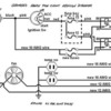
That is not the M Drew drawing I found

Does the original relay have 4 tabs (2 for coil / 2 for contact)?

You do not need to use fuse 12 for that. You are greatly reducing F11 current by removing the fan current.

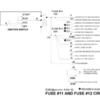
even though I like the above better, I just spent an hour on this revision so I'll post it anyway

Attachments

Images (1)
  • FUSE11AND12

Add Reply

Post
×
×
×
×
Link copied to your clipboard.
×