Hi everyone,

Need a bit of assistance from all you great Pantera experts answering so many difficult questions. Btw - thanks for always being so helpful to all in here. :-)

Now to my question - where I need help. 

I got a Pantera 1974, mostly stock, very few modifications (done from before I bought it), only real big difference is engine has been rebuilded and added MSD box. Again done before I bought it. 

I've got the problem the temperature gauge is always at "zero" or better said, at lowest possible indication. It always stays there no matter, if engine is just started or after 1 hour of driving, still "zero". 

Now my question is, what the best sequence to debug this problem?

Or perhaps some one knows what's the typical problem is in such a case?

Any help is very much appreciated. :-)

Cheers

Chris

Last edited by George P
Original Post

Replies sorted oldest to newest

The Ford temp sending unit is prone to failure. 45 years of age is a LONG life for a $6 sender. That's the first thing I'd try. Note that the sender should be in the block just below the thermostat, NOT in the surge tank. That was an early attempt by Ford/DeTomaso to fix high temp readings that scared drivers with the early 0-220F gauge. Next was a 6 watt resistor twisted, not soldered, into the rear wiring loom. They come loose from vibration. Third was a non-soldered 10-watt resistor, and finally, no resistor at all and a 0-260F gauge (with a resistor built inside) in 1973.

So your '74 car's 0-260F gauge should not have any external resistors for reasonably accurate readings, but it's worth checking. I've seen resistors crack. If it's actually the gauge, most vendors stock replacements. Fixing a stock gauge will cost at least as much as a new gauge.

If you are just troubleshooting to see if the problem is in the gauge or the sender...

Pull the wire off the sender and connect a 50 Ohm (or 30, or 20, or 100 Ohm, whatever is easy to find) resistor via a wire with alligator clips to a good ground in the car.

Your gauge (if working) will swing to full scale (or close to it).

Go from there.  It's a pretty simple - low resistance = higher temperatures.

Good Luck -

Rocky

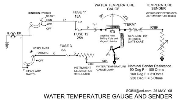
PS>  Data from SOBill, at Pantera Place.

Resistor_Temp_Guage


Attachments

Images (1)
  • Resistor_Temp_Guage

Hi everyone, 

Spend some time last night measuring continuity, the wires going from the gauge to the sensor (at least the one, I think is being used) is fine. The wires works, there's connection.  Also it seems the wires are connected correctly on the back side of the temperature gauge.

I've taken a few pictures, and will add a link to the picture here in the post. 

http://tinyurl.com/yxjxhlbd

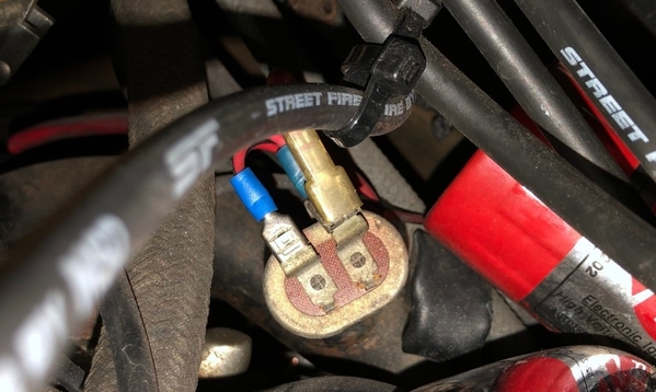
It puzzles me from the pictures, why the sensor seems to have been move to a coolant pipe....don't believe it's correct location for it. Please let me know if I'm wrong?

Also one of the wires on the sensor, I would have though should be pink (power), but it seems it's a full RED instead. Don't know if that's stock for a Pantera from 1974?

 Above one asked my if the gauge ever worked in my ownership, and the answer is no. Don't recall it ever worked.

 Haven't tried the latest ideas mentioned, but will do tomorrow. Initial one will be the resistor replacement, that sounded like a very good idea. Then I'll try the other good ideas as well. 

 Finally, just want to remember to mention a VERY BIG thanks to all helping me, really impressive, I surely appreciate it. :-)

Last edited by George P

Me thinks I have a very good idea what your problem is.

You say you’ve traced wires and they go to the temperature sensor that has two wires.

 Whether it is an idiot gauge temperature sensor or the variable temperature sensor used on the Pantera, a 70’s Ford sensor has just one wire.

 The other electrical connection is provided through the engine block. 

An idiot light sensor is just a switch that closes at a preset temperature, turning on your hot coolant light.

The Pantera gauge sensor is a actually a variable resistor,  controlling the voltage to the gauge and thus the movement of the needle. 

 I suspect you have an idiot gauge sensor and the extra wire is the ground? 

 The factory installed the sensor, incorrectly, in the surge tank where if you lost a lot of coolant the sensor would be surrounded by air not coolant.   

 Proper location for the sensor is in the face of the engine block just below the thermostat. 

Buy a proper sensor for a gauge, not an idiot light equipped, 1972 mustang. Put it where it belongs and hook up the signal wire to it.D5731510-7218-485B-8917-E1B1BABEC763

I imagine you will then have a functional gauge.

Larry 


Attachments

Images (1)
  • D5731510-7218-485B-8917-E1B1BABEC763
Last edited by lf-tp2511
BTW, the place on the engine block the sensor should go (where millions of Mustangs have it) will have a 1/4" pipe plug in the hole. Remove the plug and install the sensor, then use the factory plug to stop up wherever the sensor was. Threads should be the same.
Second note: use one turn of teflon plumber's tape on the pipe threads. If you use too much teflon tape, the sensor will certainly not leak but also may be electrically insulated from ground. That may in fact be why your current setup doesn't work. Good luck- J DeRyke

🤔🤔 Had to Google the vacuum switch that George mentioned and it looks like he is correct. Having never had a stock Cleveland in 2511 the photos didn’t ring any bells for me.

Granted, it shouldn’t be connected to the temperature gauge but if he has followed the wires to it then maybe it is, in fact, the problem? 

 I think Chris needs to do some more discovery research. 

 And take pictures and share them with us. 

Larry

Chris, Looks like some funny wiring has been done on your car which sadly is the norm after 45 years.

the SOBill Wiring diagram shows a red with black stripe wire going to the temperature sensor.

One of your photos shows a red with black stripe wire connected to your device but it has a non-factory terminal.

 I also think I see a red with black stripe wire at the gauge.  

 I suggest you get a long jumper wire and test continuity to determine if the red with black stripe wire at both locations is in fact the same wire. 

 If you find that to be the case then follow my previous advice, buy the proper sensor, mount it where it belongs  and attach the red with black stripe wire.

That could make your temperature gauge functional.

But I have no idea what you should do with the vacuum device shown in your photos  

Larry

If you want advice from a recliner want to be mechanic ;

Ignition OFF

Locate water temperature sender

  • Front of block under thermostat
  • Mid way down on the coolant tank

Disconnect single red with black strip wire from sender

Measure resistance of wire back to gauge, 100 to 200 ohms

Switch ignition ON

Measure voltage of wire from gauge, 4 to 8 volts

With wire disconnected, gauge should be full cold

Using jumper from good ground to wire and gauge should go full hot

If not, problem with gauge

Use jumper from wire to temperature sender outer hex, gauge should go full hot.

If not, installed sender is not connected to ground.

If so, replace sender.  

trouble shooting sender . . . . . (to be continued)

But suggest testing new sender before installing by measuring resistance cold and boiling water.

WATERTEMPERATUREGAUGEANDSENDER_000001

Attachments

Images (1)
  • WATERTEMPERATUREGAUGEANDSENDER_000001
Last edited by George P

Hi all :-)


Followed up on all your good advises and have take more pictures and added to the folder in the link:

http://tinyurl.com/yxjxhlbd


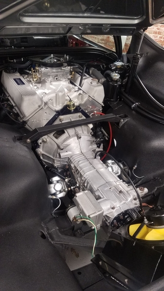
Dismantled the seats, firewall and got access to the front of the engine. 

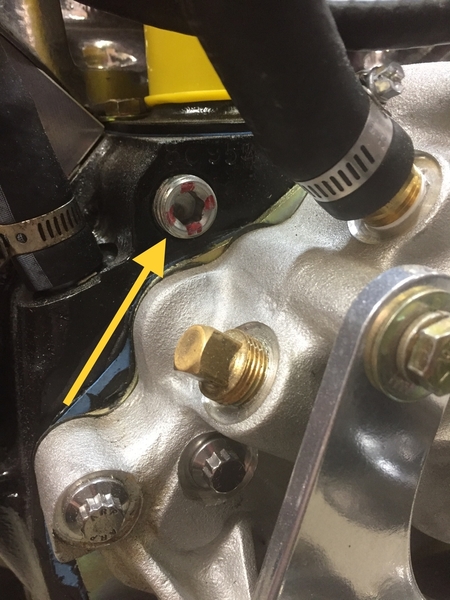
Searched for the temp sensor in the engine block, and found it, not wire on it. Hence either the previous owner disabled it, either because it didn't work or else because he wanted a different solution. I'm leaning toward that....due to the sensor the RED/BLK wire is attached to. (some called it vacuum sensor yesterday). I don't know if it a "vacuum sensor", not even sure I know what such a thing is....but on my car this sensor is place in the middle of a big metal pipe going directly to the water pumo, hence I do beleive it was suppose to work as a temp sensor - at least my guess. 

Anyway - I did a resistance meassurement on the temp sensor in the engine block, and the resistance was 373Ohm at a temperature of 22 degress Celcius (71,5 degress Fahrheit). To me that sounds to little, I would have though it should be higher - but if anyone out there know right resistance for the sensor at 22 degress Celcius, I would love to know it. Because it if its not working right, I gotta replace it, if I want to re-wire to this temp sensor, instead of the strange solution being called a vacuum sensor. 

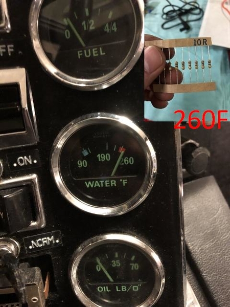
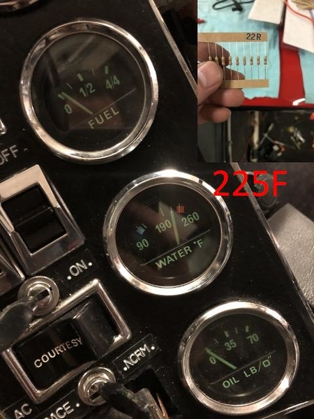
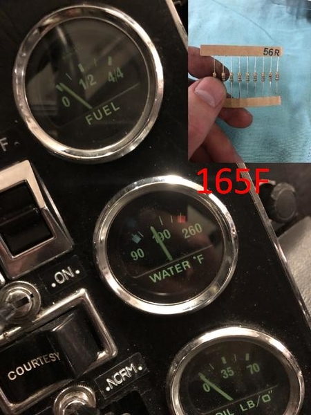
Then I continued to do testing of the Temp gauge. I toke the RED/BLK wire from the Temp gauge and placed a resistor between that wire and ground. The results can be see from the pictures in the folder. But to my knowledge it seems the temp gauge works just fine. If anyone looks at the pictures, and mean differently, I would love to hear about it. 

So this is how far I got today, based on all your help and good ideas/advises... :-)

a) Would really love to hear from anyone who can tell me how I figure out if the existing temp sensor in the engine block is working as it should? or perhaps how to test it extensively. 

b) Also would also like to hear if you all as I, believe the temp gauge works correctly, because then that can be disregarded as a source of failure.

c) Finally, I'm still puzzled about this called "vacuum sensor", was there ever place a sensor in the big metal pipe going to the water pump? or have the previous owner of my car have had he small weird projects and created something peculiar?


As always, thanks for all your interest and help :-)

Cheers

Chris


Hi Chris -

You can do an easy check on the temperature gauge on the block by:

1.  Looking at, and understanding the graph I posted.

2.  Taking your ohm meter and measuring the resistance from the center conductor of the original temp guage and the engine or a good solid ground.  With the engine cold, it will be higher than 160 ohms.

  • That's the first test.

3.  Then start your engine, and either drive your car, or let it idle until you think the engine is warmed up.  Then measure the resistance of the temp sender.  If you have a thermal IR gun, you can find the temperature of the swirl tank, or the engine block right next to the gauge, and it SHOULD match the solid purple line.

  • That would tell you if the sender is working as it should.


If it is:  Then hook the ground line on your gauge to the vehicle's solid ground.  Then hook up the "(+)" wire on the guage to your temp sensor.


Rocky


Chris, the schematic posted by Joe (JFB05177) provided temperature sender ohmage for three temperatures. Its in the lower right corner. 90 degrees F = 100 ohms, etc.

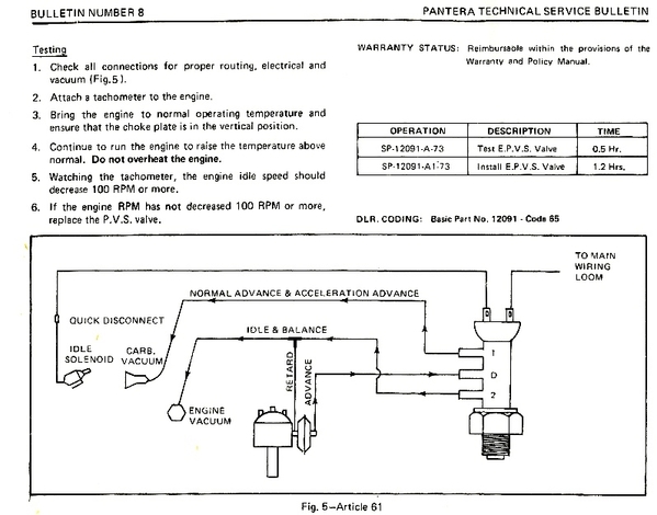
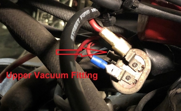
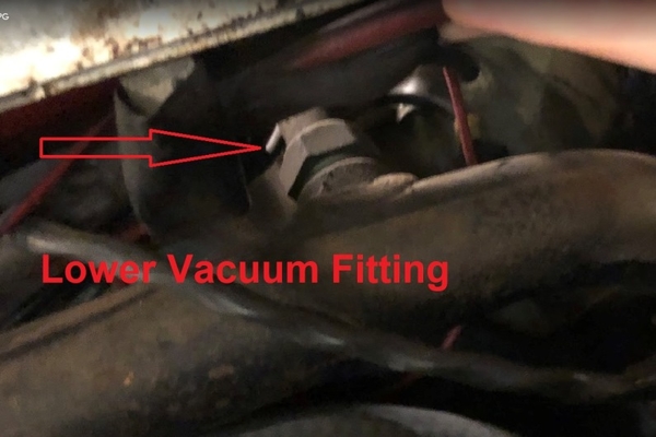
Here's the Ford documentation regarding the electric ported vacuum switch. Please note that it has 3 vacuum fittings, plus 2 electric terminals. The EPVS incorporates a switch to interrupt power to the idle solenoid, plus it manipulates the vacuum to the distributor advance mechanism. The overall purpose of the EPVS is to reduce engine idle speed by 100 rpm upon rising temperature.

Since it is actuated by rising temperature it had to be screwed into the coolant system in order to "sense" temperature.

epvs-schem

In the first picture below you can see the upper vacuum fitting, nothing attached to it.

epvs-1

In the second picture you can see the lower vacuum fitting, nothing attached to it. It is safe to say the vacuum controls of this switch have been disabled.

epvs-2

"Senders" provide a variable resistance in order to modulate the current flowing through gauges. As Larry (LF-TP2511) pointed-out previously "senders" only have one electrical connection, their other connection relies upon being grounded by whatever they happened to be attached to.

The EPVS however has two connections … because it is a switch, not a sender. True it senses temperature, a necessity of a temperature switch, but it has no provision to provide a variable resistance. 

Coolant pumps are engine driven. Does it make sense to reduce engine speed, and pump less coolant, when an engine over heats? Of course not. The EPVS did more harm than good, so my advice is to always disable it. 

EPVS

Attachments

Images (4)
  • epvs-schem
  • epvs-1
  • epvs-2
  • EPVS
Last edited by George P
Chris, I suspect the 'vacuum sensor' you refer to is a temperature actuated distributor retard system use to supplement early smog controls. Virtually all those things in the US were binned immediately after the car was bought. When they work, they foul up your tuning efforts and when they don't, things get worse. Disconnect and see if the ignition timing changes. Then reset to optimum.

the "calibration" of your gauge seemed like it is working fine.  

My question,  did you attach the resistors to ground at the wire disconnected in the engine bay?

 as for the 370 Ohms when cold,  was one lead to the engine block OR to the sender hex.   there could be some added resistance due to the thread sealant.

I took some guesses at what I though the needle was indicating with your calibrations resistors and put that on the graph.   It appears that a couple of the aftermarket senders would work close with that gauge and be "dead on" if using the OEM +10


IMG_0246_10ohm_resizedIMG_0244_22ohm_resizedIMG_0242_56ohm_resized260 gauge

Attachments

Images (4)
  • IMG_0246_10ohm_resized
  • IMG_0244_22ohm_resized
  • IMG_0242_56ohm_resized
  • 260 gauge
Last edited by jfb05177

I have the exact opposite issue with my temp gauge.  It moves all the way to the right (hot) when I turn the key on, even before the engine is running and stays there. I've checked the engine temp and it is not at 230 degrees so I have an issue with my gauge, wiring or sending unit.  I checked the wiring and the gauge is correctly wired (there is a resistor on the red/black wire that I soldered when I did the wiring but I didn't change it) and the red/black wire is fitted to the sensor on the other end.

The replacement sensor that I installed (in the right spot in the block) was an AirTex Wells 1T116 which is specified for a 72 cougar with a 351 Cleveland.  This sensor cross references to the following part #s: 12336872, 2132767, C6DZ10884A, C6DZ10884B, D0OZ10884A, D0WY10884A, D0ZZ10884A, D9HZ10884A, D9TZ10884A, E1ZZ10884A, F1SZ10884A, F2CZ10884A, F3CZ10884A, TU25, ZZL018840, ZZM018510

I used teflon tape on the threads, maybe two wraps, and have not yet tried to take some off.  Is the tape a potential problem in my case? Can I check by leaving the sensor installed and running a wire from its base to ground? Or do I just have the wrong sensor? 

Dunno on your tape job but the simplest way to check is to ground the brass sensor body with a patchcord. If the gauge then works, try one wrap of teflon tape. In stubborn cases, I've seen owners solder a separate ground wire to the sensor body. But since I've never cut one up I don't know if that potentially damages the sensor. Good luck- J DeRyke

thanks - first test will be a jump wire from the sender base to a good ground. if that doesn't work, I am inclined to try the old sender (have no idea if it works as car wasn't running when i got it) or a new TS58.  Third test will be to remove the inline resistor on red/black wire on back of gauge to see what effect if any that has (given that it''s old, it's suspect).

Any other thoughts?

My temp guage was reading high and even going to the hottest reading although my lazer temp gun said my car was running fine. I called Steve Wilkinson and he asked if I painted the back plate on the ZF when I recently had it out of the car. Turns out I had a bad ground because of the paint so I cleaned the paint off where the ground strap goes and now my guage works as it should. Thanks Steve!

I did a few tests this weekend.  First i ran a jump wire from the sensor to a good ground which made no difference - the gauge still went to 230' as soon as the key was on. Then I disconnected the wire to the sensor and as expected, it went back to 0.  Then I quickly took the Red/Black wire to the sensor and grounded it and as expected, it pegged the gauge again at 230'.  Then I changed the sensor for the one that was in the car when I bought it and there was no change.  The ground strap on my ZF is clean and I also added a thick ground strap from the starter to the chassis and I don't have issues with other electronics in the car related to a bad ground.

So, the next step will be removing/testing the temp gauge - Any pointers on which steps to go through in doing this would be very appreciated.  I have pics of the wiring on the back of the gauge from when I installed it and it appears correct based on the SOBill wire diagrams.  I am a little suspect of the in-line resistor - any help would be great - Thanks 

427390 posted:

I did a few tests this weekend...

do you have access to some resistors and perform a test of the gauge's calibration like BRYSKE (Chris) performed.

measuring the resistance of your installed sender would be a start.   If it's value is in the COLD region, that alone would indicate a bad gauge

added...

Measure the resistance of the wire to the the gauge with switch off and the voltage of the wire unplugged from sensor with switch on.   this will let you know if the gauge is grounded at the dash.   the gauge as a "voltage divider" should have about 0.45 X battery voltage at the unplugged sensor.


Last edited by jfb05177

If only you closed by, you could easily borrowed my packages with resistors. :-)

It's a great way to debug the problem.


Btw - to everyone else, I've not forgotten this thread. I still need to do more work and tests, but haven't had any time at all the last two weeks, but I hope to be able to work on the car some time next week. 

But still want to remember once again to thank everyone for helping and contributing  to the thread - very appreciated :-)

Some basic info from the aircraft mechanic.

Temp instruments and their senders are a matched couple. Viglia gauge and Viglia  sender. It could care less and doesn't know what engine it is installed on.

I am guessing that Viglia who has made gauges for many European cars did not have a temp probe that fit a US 1/8 in. pipe fitting so Ford added resistors (a patch) so their probe would work. Dropping the gauge feed voltage by using a resistor will work but not give accuracy through the full range.

If you are seeking super accuracy  the way to go is to send the gage and sender to a instrument repair shop. They can set you up with a gage / sender combo that will give you an accurate temp reading. 

Chances are with the 40 year old wiring, gauge and patched together sender you will have error in the reading. I have used West Valley Instruments in the past with great results. My instruments come back looking new and working.

The Temp switch (EPS ?) was used on dual diaphragm distributor to retard timing at idle to reduce hydrocarbons. It ported man psi to the retard diaphragm and that retarded the timing. If you are running an MSD ignition then it's of no use. Don't they have programmable electronic spark advance ? 

It would be interesting to know just what that switch is wired to . Are you running the original 4300 carb with a throttle solenoid for fast idle ? I think that is the power feed take off for the switch.


Thanks for the replies and i will try the suggested tests....The wiring in the car is original but in very good condition and all terminals were cleaned and treated with dielectric before re installation.  

JFB05177 - one of my theories is that the gauge ground is NG and I will check that as well as your other suggestions - thank you

Punkdog - it's an original veglia temp gauge with the sensors that others on pantera boards have verified as the most compatible with the gauge. I am also familiar with how to improve the accuracy of the gauge with resistors and tests, but first I need to figure out why it isn't working correctly at all.

To answer your questions, I have no temp switch/EPS nor an MSD nor the original carb (I am running a duraspark ignition and Edelbrock carb).

The wiring is pretty straightforward with the red/black wire to the sensor and the correctly color coded wires to the back of the gauge (which I verified with pics I took upon installation compared to the SOBill wiring pics)

At this point, I need to pull the gauge cluster, get the VOM and see what's up

pantera engine rebuild

Attachments

Images (1)
  • pantera engine rebuild
Last edited by George P

As previously said here, the temp sender has one wire. The EPS has two - 12 volts and ground.

Again, unless you have a dual diaphragm vacuum advance on the distributor the EPS SWITCH is unused. Most like me who have the dual diaphragm distributors just disconnect it. So what is the EPS wired to and why ?

Smart and easy money is on the sender. Buy a new one then install it where it belongs ( in the block ) and see what you get. Just assure the ground  - sender to the block is good and that the block to frame is good. There should be a ground strap of engine to frame. If still inop then it's probably the gauge provided there is voltage at the sender. If still inop then send both sender and gauge out for bench testing. Keep in mind that a lot of parts being sold these days like temp senders are Chineese junk. So an out of box failure is not uncommon. That will drive you crazy if you let it.

Good hunting.

So sorry , I thought the pictures posted of the EPVS not EPS were of your car.

Going off topic ( oil temp gauge ) I thought that I had the EPVS switch - valve figured out but looking at the diagram of it I am confused. The diagram shows the retard side connected to manifold vac and the advance side to carb / ported vac. How's that work when carb vac is less than manifold vac ? I thought it was meant to advance the timing when at a high temp idle. For that matter how does the vacuum advance ever advance with the retard side constantly connected to manifold vacuum ?

Getting old sucks


punkdog posted:

... Keep in mind that a lot of parts being sold these days like temp senders are Chineese junk. So an out of box failure is not uncommon. That will drive you crazy if you let it …

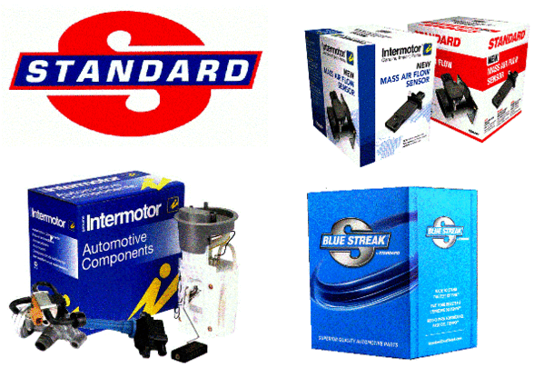
Every "manufacturer" cross references their part numbers to SMP's part number for the equivalent part (SMP = Standard Motor Products). SMP is the big dog in the parts business, they have an excellent reputation for providing OEM quality parts. I've been purchasing SMP parts since the 1960s, I've never been burned by them yet. They are the parent company of Blue Streak (premium ignition parts) and Intermotor (import parts).

SMP parts are sold by independent parts stores (a dying breed) but can also be found on eBay and Amazon. The chain stores sell Wells, Air Tex, etc which are Chinese parts.

SMP

Attachments

Images (1)
  • SMP
Last edited by George P

I have to call my instrument overhaul guy tomorrow to find out the correct sender for my oil psi indicator. I thought it was wrong so I cross checked it with a certified test gauge. It was over 20 psi low on the bottom end.  If I have the P/N of his water temp indicator I will also ask about it. I had all the gauges in my 1976 TR6 overhauled including tach and speedo and it changed everything. Turned out that it had defective water temp sender installed

Sad to say but I have had some bad luck with today's Chineese electrical parts. An out of box failure of a new part when trouble shooting will drive you crazy because once replaced you should be able to eliminate that part from the process.

Vegletti Borletti has made good quality instrument for many different cars for a long time but after 40 plus years they can loose calibration. I'm way past 40 and totally out of calibration. I check for the P/N before calling my guy Morris.

Add Reply

Post
×
×
×
×
Link copied to your clipboard.
×