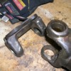
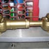
Here's the Quella PPC kit.
Best,
Kelly
Kelly,
What is the thickness of the adaptor? Is it Aluminum or steel?
I've been thinking about this for some time.
Thanks,
Mark
What is the thickness of the adaptor? Is it Aluminum or steel?
I've been thinking about this for some time.
Thanks,
Mark
Mike,
I'm pretty sure the caps on the U-joints weren't spinning. I'm having trouble pressing them out. Do any of you guys have some tricks on easy ways to remove the caps?
I'm pretty sure the caps on the U-joints weren't spinning. I'm having trouble pressing them out. Do any of you guys have some tricks on easy ways to remove the caps?
quote:Originally posted by geoshanna:
John,
Thanks for the explaination on that. Now maybe I can rest easier not worring about the ZF. Just have to replace all the U-Joints.
George
That is great news! First I would clean the yoke and U joint good with solvent so you can see all the parts well. Then remove all the snap rings and the grease fitting in the X part of the U joint. Start by supporting the yoke so the bottom cap has clearance to be pushed out. Using your press, press down on the top cap. That will push the X down and bottom cap out. Remove the bottom cap and turn the yoke over. Set your press on the X part of the U joint through the Yoke hole and press the X down and that will press out the cap at the bottom end. Repeat for the other caps.
Mike
Mike,
That's what I've been doing, but on a couple of the caps it's taking quite a bit of force and they aren't moving. Does heat help the process or some sort of penetrating oil?
That's what I've been doing, but on a couple of the caps it's taking quite a bit of force and they aren't moving. Does heat help the process or some sort of penetrating oil?
The caps might be corroded to the yoke so some penetrating oil might help. If that doesn’t do it you might need to heat the yoke around the caps a bit.
Mike
Mike
When you put the new U joints back in the yokes you will need to be very careful not to have a roller bearing fall out of place and get caught and pushed into the bottom of the cap. If it does it is toast!! It is helpful to start by removing the zerk off the new X part and then pushing the X way into the yoke. Then the cap can be positioned on the end of the X so the bearings say in place. Push the cap in all the way past its normal position so the X extends all the way into the other side of the yoke. Install the other cap on the X and push everything back so the clips fit. When you get all done put the zerk back on.
Mike
Mike
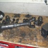
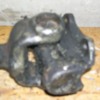
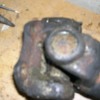
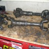
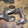
First off, Thanks! for all the helpfull tips. I got the broken shaft taken apart tonight and the end caps on both sides looked in need of help. Came apart with some oil and heat, but did come apart after a few trys and figuring out where to apply the pressure with the press I'm using. (From Work) Tomorrow the broken shaft goes to work to get cleaned up. New U-joints have been ordered. Thought I'd break down one shaft at a time in case I have problems since I still have Larry w.'s spare shafte here. Here is a shot of the whole mess taken apart.
Attachments
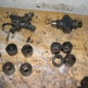
The broken side vs. the other side. (Broken is on the right, in case you can't tell)
Attachments
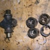
Close up of broken U-Joint.
Attachments
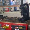
The "Beast" of a press I used. Again, after a while it was easy. Suppose you could do it with a regular bench vise.
Attachments
More to come as I progress.
George
George
Great news that it came apart OK.
Mike
Mike
George,
Did you mark the orientation of the u-joint flanges? I dont know if it has been mentioned but many stock half shafts assemblies have been balanced. You might see a small weight welded on. Sometimes it's quite noticeable in top gear if mixed up when reassembled. Are there any small weights or grind marks?
Best,
Kelly
Kelly, Mark Johnson also used to make CV companion flanges for Pantera axles. If I recall, Mark's were between $300 and $400 each. I'm sure he could be convinced to make a set if someone wanted them. Mark cuts the spline slightly smaller than stock, in order to correct the OE companion flange's sloppy fit on the OE axle.
Kelly,
I did not notice any weights welded on the one I took apart. I do know which is the inboard and outboard flange. Would it make a difference as to a top or bottom reference?
I'll check them for weights or indexing marks when I get home today.
Thanks for the tip.
George
I did not notice any weights welded on the one I took apart. I do know which is the inboard and outboard flange. Would it make a difference as to a top or bottom reference?
I'll check them for weights or indexing marks when I get home today.
Thanks for the tip.
George
Ok,
Got home and looksed at all three shafts (Larry W's included) Mine have no weights in the shafts be on the flanges. Larry's is on the shaft.The first pic is of the shaft I have not taken apart. ( Sorry it's blurry...battery was getting low on the camera)
There is a weight there on the bottom side of the flange on the outboard side of the shaft.
Attachments
On the in-board flange there is a weight on the opposite side than the in-board flange. In both cases there are weights on both sides of the flange. On the same side.
Attachments
I set both shafts up in the same position with the fittting on the bottom side.
Attachments
This is the one one I took apart. I placed the flanges like I think they should be like the ones I haven't taken apart.
Attachments
In-boardside flange with the weight opposite of the out-board flange.
Attachments
This one is of Larry's. His are on the shaft, one on top and one one bottom. (His were ballenced after he re-built them. So I'm guessing that the way I had the flanges lined up should be good. If someone knows better, please let me know.
Thanks
Thanks
Attachments
quote:Originally posted by ehpantera: Kelly, What is the thickness of the adaptor?
They're about 1/2" thick but they only added about .390" to the stacked height because they had a recess to align the CV.
quote:Is it Aluminum or steel?
4140
quote:I've been thinking about this for some time. Thanks, Mark
I dont think Mark sells them any more but Dennis Quella at Pantera Performace Center has them and also ZF stub axles and companion flanges for CV conversions like I previously posted. I dont know if Dennis will sell the adapters without joints shafts and boots. I dont know what the prices currently are but they're probably pretty pricey. You'll need to give Dennis a call on $.
Best,
Kelly
quote:Originally posted by David_Nunn:
Kelly, Mark Johnson also used to make CV companion flanges for Pantera axles. If I recall, Mark's were between $300 and $400 each. I'm sure he could be convinced to make a set if someone wanted them. Mark cuts the spline slightly smaller than stock, in order to correct the OE companion flange's sloppy fit on the OE axle.
Hey David, Mark Johnson doesn't make them any more. The Williams product is identical to what Mark Johnson used to make, just double the price
Kelly,
Any thoughts on the oriantation of the flanges on my half shafts?
Any thoughts on the oriantation of the flanges on my half shafts?
How about looking back at the pictures you took before you disassembled it.
Mike
Mike
quote:Originally posted by geoshanna: Kelly,
Any thoughts on the oriantation of the flanges on my half shafts?
I think either recreate from pics as Mike suggests in his post above or resign yourself to having them rebalanced after you rebuild them. If latter, dont paint and/or pretty them up them until after balancing.
Best,
Kelly
I looed at the "before" pics and I think I'm on the right track here. Before I took the shaft off the car, the weights were 180 deg. from each side like the shaft that didn't break anf Larry's. From the picture it appears that way, but with rollong the car on and off the flat bed, could that have changed the alignment? The shaft was rotating both going on and off the truck.
You have four flanges, two shafts and the timed orientation of each spline to deal with. That's quite a number of reassembly possibilities.
My advice would be to take a die grinder, remove the existing weights, assemble them without worry, and take them to a drive shaft shop for proper balancing. Any drive shaft shop should be able to do this for you. You should order new felt seals for the sliding spline joint while your at it. Make sure you have a proper set of bolts and locking nuts. You dont want an instant replay. Afterward, do whatever cosmetic work you want and you'll be assured of only having to do the job once this way.
Best,
Kelly
Ok,
The new U-Joints are pressed in and will install them tomorrow to see IF I have a vibration or not. The last question is how do you know if you have enough or too much grease in the joint or shaft?
George
The new U-Joints are pressed in and will install them tomorrow to see IF I have a vibration or not. The last question is how do you know if you have enough or too much grease in the joint or shaft?
George
Not enough grease and the joint fails in a few hundred miles. Too much and the spinning shaft throws it all over the trunk!
Good point though- ALL u-joints come with only protective anti-rust grease inside so they all need greasing befor you drive to Colorado or the like. I hand-pack the 4 cups (non-zerk-fitting u-joints) with enough grease to get a little squeeze-out during assembly, and use a grease gun to just get a little oozing out of the seal on the greasable ones. Some owners add stainless steel spatter shields to the compartment; too much grease is way-better than not-quite-enough!
Good point though- ALL u-joints come with only protective anti-rust grease inside so they all need greasing befor you drive to Colorado or the like. I hand-pack the 4 cups (non-zerk-fitting u-joints) with enough grease to get a little squeeze-out during assembly, and use a grease gun to just get a little oozing out of the seal on the greasable ones. Some owners add stainless steel spatter shields to the compartment; too much grease is way-better than not-quite-enough!
Thanks Boss. I think the previous owner of my car liked ALOT of grease as it took ne 3 hours to get the shafts cleaned up before pressing in the new u-joints. I got the greasable joints and will grease thme until I see a little bit of grease coming out the seals.
Thanks for all your help and pray for no vibrations after the install later this weekend.
George
Thanks for all your help and pray for no vibrations after the install later this weekend.
George


