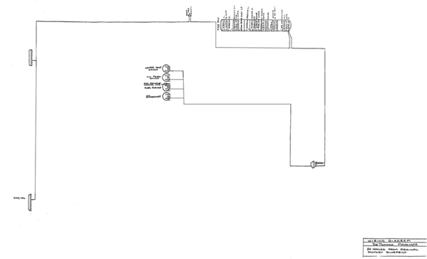
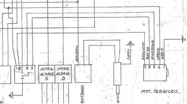
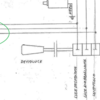
Does anyone know what this part is supposed to be? Seems to connect to the brake light switch and most of the gauges (possibly to a ground for the gauges).
Replies sorted oldest to newest
do not know this type of diagram. Well the real stuff is here..http://www.panteraplace.com/page107.htm. It is D T Technical Information, pretty comprehansive.
In the above subsection it shows ALL the wiring by LOGICAL view.Pretty complete, some stuff differs by car model.
I used it for a full rebuild..and enhancements..
Matthias
quote:http://www.panteraplace.com/page107.htm
it's the wiring diagram that Hall Pantera sells, I don't think they'd like me posting it for free. It's hard to read and some of it makes little sense, so I've been redrawing it in AutoCAD, but some parts are unmarked (like the one circled).
The link you provided is for Pantera's, is it fairly close to the Mangusta's?
I was just going to follow connections and see if it helped identified it
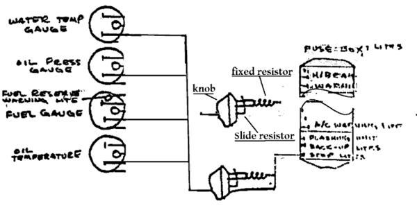
I would also say it is the instrument illumination dimmer.
However, the wiring implied the illumination is on all the time! Do the brake lights only work when the ignition is on?
to me, the drawing implies there is a fixed resistor before the rehostat. the lower line implies there could be a Full Bright setting at maximun dial
Attachments
I appreciate your help, it was one of several pieces unlabelled and the only one I was at a total loss for.
This is one area that I was never successful in.....trying to get more juice out of the dash gauge lites!!! There was "on" and then various levels of "can't see shite"! I tried some LED bulbs with no luck....some higher wattage standard bulbs with a tad bit of luck..... but never took the time to jumper out the dimmer to see what things looked like!!!
My bad! 99.9% of our driving time was during the day......and the lamps were lit "OK" as long as you weren't in any sort of high ambient external light conditions (Big street lamps etc)
I vote for the dimmer switch on that device!
Watch out for lines shifting across page breaks in the schematics.......!
Steve
PS: I don't believe that the fuel "reserve warning" feature was wired up on many......if any.....
M!ke, I've started my winter vacation doing the most possibly exciting thing (studying the Goose wiring...) and wrt to this question, I think you actually had the answer yourself on another post (Oil Pressure Sender Woes). I'd first thought this was the gauge dimmer too, but I think the mystery device here was intended to be a voltage regulator for the gauges. Interesting on the original (Italian) schematic, the positive terminal for the gauges (for those that have senders, the oil/temp/temp/fuel) is connected directly to the fuse position, but on the Hall schematic this mystery device is between the fuse box and the gauge Positive voltage reference for the gauges. British cars used something like a Lucas 37584, in Lotus Europa mounted on the back of the temp gauge.... Maserati Ghibli used a voltage stabilizer but the footnote seems to be only when with Smiths gauges https://www.maseratinet.com//p...abilizer-gauges.aspx
Without such a regulator, the gauges will almost certainly drift as the Alternator speeds up...So convenient to use, in case you like the comfort of lowering the engine temp by turning on the lights ![]() ...But neither is it clear that anything was actually installed, the parts diagram for the Goose doesn't include any such device (well, neither does it include a switch for the parking brake, which shows up on both wiring diagrams but maybe not a single car...!). I would have expected such a device to be on the firewall next to the horn relays and blinker cans, but I never saw anything on '1076 (and you may just follow the path and convince yourself it wasn't ever there...). Lastly, from what I see from Pantera schematics http://www.panteraplace.com/page107.htm there was no such regulator for the Pantera either.
...But neither is it clear that anything was actually installed, the parts diagram for the Goose doesn't include any such device (well, neither does it include a switch for the parking brake, which shows up on both wiring diagrams but maybe not a single car...!). I would have expected such a device to be on the firewall next to the horn relays and blinker cans, but I never saw anything on '1076 (and you may just follow the path and convince yourself it wasn't ever there...). Lastly, from what I see from Pantera schematics http://www.panteraplace.com/page107.htm there was no such regulator for the Pantera either.
For certain, adding the voltage regulator will cause all the gauges to read lower (since the regulator will drop the voltage to the gauges...), so this may answer the question you had ) but do nothing to help you on the problem! ![]() ).
).
Fun looking at the wiring diagram, I had never noticed that the Hall trace left off the interior fan switch ! Lee
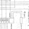
ps. Note, see attachment...another connection missing on the Hall trace is thru the Alternator bulb; The alternator lamp is not grounded, one end shares the Battery voltage (coming from the fuse and feeding the gauges), using a pink wire (the same as used also for the gauge's 12v reference). The other end of the alternator lamp follows a white/black wire to the 'i' terminal of the voltage regulator--this is feedback for the voltage regulator to control the field current in the alternator...A great picture of this is Bill Taylors Pantera drawing, below are the Hall vs. DeTomaso diagrams. 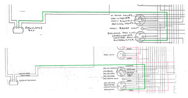
Attachments
Good guess - voltage stabilizer for you temp instruments and oil psi if not a direct read.
A very creative symbol never seen by me
Lee, from my alternator woes, I learned that the alternator light has power whenever the key is on... when the engine is not running the alternator actually provides a ground to complete the circuit, thus illuminating the alternator light. When the alternator is producing power there is no ground (that terminal then actually produces +12v) so the light so goes out. reverse logic, but it works...
MH
now that it is stated, that does illustrate the MECHANICAL voltage regulator.
Been a while since I messed with the one on the TR6, I works by the resistor getting hot and breaking contact, so it really pulses the 12VDC so the average is 5 V
Oh, here is my theory: Hall traced an early version of the schematic. My reason for guessing this is the wiper motor shown--in the Hall schematic, shown as a 4 wire motor but in the Italian schematic (dated 11-1-68) and as installed in 8ma1046, definitely a 5 wire motor.... Everything you want to know about Lucas wiper motors are here, http://www.mgb-stuff.org.uk/wiper3.htm#none
somewhere around ~1967 Lucas transitioned from 4 to 5 wires and 2 speed motors. The 4 wire motors took +12v to the motor and switched ground, the 5 wire motors mux +12v in the switch....Originally I followed the Miura wiring, http://www.huskyclub.com/tavwiper.html , but the Italian schematic is consistent with the +12v used for parking...Lee
an interesting observation. The Italian version of the wiring diagram shows the 5 wire whereas the Hall shows the 4 wire wiper motor.
The Italian version also shows the front side lights (but not rear) and they're not in the Hall version.
The Italian version also doesn't include that mystery part.
They both include the non-existent backup lights.
Good catch...
MH
Euro cars do not have rear side markers.
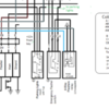
Thanks, Denis, I never noticed ! Another small detail that seems to be in Euro cars only is a relay around the "flasher" circuit, which is also in the Parts manual (item 21 on the electrical page, "dolo por il tipo Europa")...But I cannot make sense of the electrical connection. So how Do the flashers work on the Goose ? Lee
Attachments
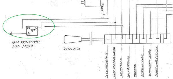
Lee, I'm not with paper schematics at the moment so won't comment on the hazard flasher issue until later (....only guesses vice facts on this confusing issue anyway.....) As for your first attachment, the circled element appears on my US spec car, and it's the a third Carello relay associated with the headlight circuits, located under the dash just to the left of the steering column. Seems like it may not have been fitted to early cars but I'm not positive. The incoming (heavy gauge) wires come from the connection blocks also near the steering column; they are full terminated leads, not spliced-in connections as the diagram suggests). I'll post how i think 1010 was originally wired in a day or two, can't recall now whether it matched the schematic or not. In general this relay kept high and low beam amperage out of the stalk switch, can't imagine how this was addressed on early cars if they in fact didn't have this relay!
Nate, good news, you can remove this one from your Christmas to-do list... ![]() While just now writing to describe how it made no sense, suddenly it made sense: This circuit forces on the low beams when the High beams are on. Is that a difference between US and Euro cars ?
While just now writing to describe how it made no sense, suddenly it made sense: This circuit forces on the low beams when the High beams are on. Is that a difference between US and Euro cars ?
I looked at a fuzzy picture under the dash of 1046 and saw that relay, but it didn't have the black terminal covers around the end and I just dismissed it as a modification...! See attached, I've been saving money on Christmas presents by proofreading a wonderful re-draw of the diagram (instead of shopping)...!
But as I see it;
- headlight power comes directly from the ignition switch to the first toggle switch, then to the indicator stalk via the Gray/Black wire--there is switched by the turn signal switch for High or Low beam, then out to the headlamps via fuses 1 and 4.
- The 'headlight flash' circuit bypasses the toggle switch; power sources from fuse 7 (brown wire, turning to Blue-brown at the junction). The "flash" connection in the Lucas stalk provides an alternate path to the high beams.
- The Carello relay 22.900.000 part (aka Sipea T5170) terminals 85 and 86 seem to be universal designation for the solenoid power, as well "87" seems to be common for "normally open" (and "87A" means "normally closed...).
This is simple, when the high beams are turned on, the relay closes and (using the power from F7) turns on the low beams.
(note the schematic refers to terminal 80/51, and the other markings I see for example the Carello look-alike 4263598 say 30/51 but at least there is really no other way to explain this relay...!).
Appreciate comments on whether it really all works this way ! The downside for the circuit is that yes, it seems that the current thru the "Flash" wire would get quite high when the parking light switch is turned off (since all the current would come from the F7 patch, instead of the normal operation current is shared between F7 and the ignition key path...)….Lee


