Hi all,

I open this topic to have some online assistance for my head porting.

My 351C 4V CC head had a bad repair see here http://pantera.infopop.cc/eve/...562/m/4111096556/p/1 iron guides were cracked.

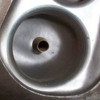
I removed completely the old guide on one of the exhaust ports. Let me know what you think.

Next step is removing the booster ring on intake side, and I am wondering if it is really worth cutting the remaining guide boss that holds the bronze guide, maybe I should only reduce the OD diameter and give the right radiuses to reduce turbulence in the area ?


Intake side :


Original Post

Replies sorted oldest to newest

They are nice now. If you remove the ring on the intake, that is considered a racing only modification.

The ring was originally cast into the intake on the Boss 302 iron head.

The 69 also used a 2.21 intake valve and switched to the 2.19 in 70.

That was an attempt to build more off idle torque in a street engine.

The iron 351c 4v head is a continuation of the thinking by Ford of the Boss 302 issues solving for STREET cars and engines.


What you do now all depends on what you are going to do with the engine?

Porting iron 4v heads is controversial. Many head porters will say leave them alone but what happens is the bottom cut of the valve seats, the angle can vary for differing results.


I personally think it should be completely blended into the port at around 90 degrees?

The Ford Boss 302 modification illustration from 1969 shows that in a cross section.


The problem with that is it wasn't the final race configuration of the head necessarily.


As far as removing completely the remainder of the iron cast in valve guide, consider that a support for the bronze guide. Don't go any further at this point in removing more of it.


My A3 Motorsport heads DO have that bottom cut as part of the port pocket with no indications of ever having had the ring.

If you CC that port it will be right around 238cc. It's a big port.

Others will tell you that the C302B head has a smaller port but flows as much with a smaller valve.

You probably would benefit from speaking to Dan Jones who has done dyno work on various combinations and could point you in the right direction.

He works with an experienced "Cleveland" engine builder with a bunch of flow bench/porting experience on these engines.

Those are two that you could seek their expertise on before you over port these heads?


You PROBABLY don't need to do much with the intakes now BUT the exhausts on the iron heads to race need radical porting and the roof needs to be raised.

Stock the exit angle is wrong.

This is where you see the race heads with the 1" aluminum plates installed to change the angle of the port upward.


When the aluminum Motorsport heads first appeared, Don Nicholson was asked about them.

Basically he was not impressed with them at the time. His comment was that he was getting over 800hp with the iron heads back in the day and that the Aluminum heads didn't.

So you will get all sorts of opinions on this subject and PROBALBY the thing to do is what new car manufacturers do, model your car after what the other guy did (who was successful), like Ferrari vs. Porsche, borrowing (stealing) only the best ideas of the other? Wink


It is unclear to me IF the Detomaso race Panteras had that exhaust port modification on them or if it was even allowed under the rules then? I was told yes they did have the mod but I've never seen anything that would "corroborate" that statement?


So far the ports look good with the guides.


Do a search for Dan Jones posts on this forum. It will lead you to some of the information that you need and cross reference to other links as well.
Last edited by panteradoug
Hi Doug, thanks for the feedback.

Can you show me this Ford picture about the port showing the modification ? blending means that I cut the remainin material arround the pressed guide, or remove the booster ring ?

For the porting I was following what was said here : http://www.351c.net/archive/te...ic-porting-4v-heads/

My car won't be a race car It will be for road, I live on country side, and I have shock towers, so the best for me is the geometry that will give the best power curve taking into account that I will leave with this unefficient exhaust port and I would like an engine that goes above 6500 rpm, I don't want a second diesel car Wink even if it is a 400 hp one.

If I do not remove the ring and the material arround the guide, do you think I should smooth the walls ?

And one big question I have, I have new EPN stanless steel valves, which seat cut should I do ? I was think about a classic 3 cuts 60/45/30, this is the next step for my heads after having ported and pressed the guides.

Jérémie
quote:
Originally posted by Jérémie:
Hi Doug, thanks for the feedback.

Can you show me this Ford picture about the port showing the modification ? blending means that I cut the remainin material arround the pressed guide, or remove the booster ring ?

For the porting I was following what was said here : http://www.351c.net/archive/te...ic-porting-4v-heads/

My car won't be a race car It will be for road, I live on country side, and I have shock towers, so the best for me is the geometry that will give the best power curve taking into account that I will leave with this unefficient exhaust port and I would like an engine that goes above 6500 rpm, I don't want a second diesel car Wink even if it is a 400 hp one.

If I do not remove the ring and the material arround the guide, do you think I should smooth the walls ?

And one big question I have, I have new EPN stanless steel valves, which seat cut should I do ? I was think about a classic 3 cuts 60/45/30, this is the next step for my heads after having ported and pressed the guides.

Jérémie


The diagram shown there is the same one as was shown in the Ford Boss 302 book.

If you follow that, it is removing the ring.


60 degrees is going into the port. You will have to blend or smooth that into the port.

Some will use an additional cut there with a stone of about 75 degrees and just leave the edges alone.

I don't think it matters too much which way you go, that cut is ALMOST a matter of tuning the head with the rpm and the cam lift and durations?

You do not polish the inside of the intake ports on an iron head 4v. The rough as cast walls will "co-operate" more with keeping fuel vapor in suspension in the port.


You need to realize that some of the work done to these ports is for rpm use well above where you intend to run your engine and therefore is useless or even damaging in some respects.

The point of Ford on these ports originally was they needed NO porting on them as cast.

The ring is usually the area of discussion or controversy on them though.

I do not know at which rpm the cast in ring becomes restrictive or restrictive significantly?


With the exhausts there are at least two issues. 1) the angle turns down instead of exiting up 2) the header tubes turn down 3) the Mustang chassis will not allow the ports to exit up.

So the answer is the exhausts are what they are and ultimately are the rpm restrictors to your engine.

I do not know at what rpm that all transpires?


Let me just say though that it isn't unusual at all to have the Ford aluminum head engines showing around 700hp and the iron 4v head engines in the 450 to 500hp areas.

There are quite a few of them running around on the street to verify those numbers.

I can hear the differences in the exhaust sounds between the two. The aluminum head engines have a scream to them not unlike the Indy engines do and the iron heads have a drone to them?


In my experience that plays into the exhaust tuning of engines and is where you can gain 150 hp through the exhausts over another car?

That exhaust frequency is definitely an indication. The higher the frequency, the better.


The fastest cars on the track ALWAYS have that HIGHER FREQUENCY exhaust scream to them. It isn't a coincidence?

Also, we are talking about hand made headers (as if you could cast them up, right?) and here the cost starts about $3,500 for a set of them? These guys use a computer to calculate every tube along the way and match it to your gears and cam profile.

Change those and you need a new set of headers? Wink
quote:
And one big question I have, I have new EPN stanless steel valves, which seat cut should I do ? I was think about a classic 3 cuts 60/45/30, this is the next step for my heads after having ported and pressed the guides.


There was an interesting article in Popular Hot Rodding (a pretty good mag, back in the day) saying that a steeper valve seat (50 Deg, vs. 45 Deg or 35 Deg) resulted in a dyno'ed Torque and Horsepower improvement. The peak torque moved up in RPM, and the Peak HP moved down in RPM.

See if you can find it in the March 2012 issue or Popular Hot Rodding.

Interesting article. The test engine was a Chevy Vortec.
With a valve seat angle of 45° air flow increase shall be most linear as valve lift increases. Valve seat angles straying from 45° create a non-linearity. Valve seat angles greater than 45° shall favor high lift flow, valve seat angles less than 45° shall favor low lift flow.

The 351C 4V intake port, out of the box, has a valve pocket throat diameter of approximately 1.75" (2.40 square inches area), and will thus reach the limiting port velocity (sonic choke) at 7344 rpm (357 cubic inches). Whatever you do, do not "open-up" the valve pocket throat diameter more than 1.90 (2.83 square inches area). Opening up the throat larger than that will negatively impact the intake port's performance. At that throat diameter limiting port velocity is reached at 8660 rpm.

The quench chamber heads shroud both the intake and exhaust valves in places, and air flow (especially low lift air flow) can be improved with a bit of "un-shrouding" in the combustion chamber. As is true for any cylinder head, you want a nice, smooth, well blended transition from the valve pocket to the throat, a "rounded" throat, a nice, smooth, well blended transition from the throat to the valve seat, and from the valve seat into the combustion chamber. No recessed valve seats. Recessed valve seats must be blended to remove the sharp edges and smoothly blend the seat into the combustion chamber, or seat inserts can be installed to thus eliminate the recessed seats. This detail work will net you the most performance from the cylinder heads.

If your headers (or exhaust manifolds) are the type that turn-down and hug the engine then you want to leave the flat roof & the bump in the exhaust port, and also leave the exhaust port floor as-is. Those features in the exhaust port were put there to aid the port's performance when the headers/manifolds turn abruptly downward.

Intake valve seat width no less than 0.060", exhaust valve seat width no less than 0.080", and seat run-out no greater than 0.001".

Here's a picture of outstanding intake valve pocket & valve seat work. The combustion chamber could stand some un-shrouding at about 4 o'clock, and from 6 to 8 o'clock. However the un-shrouding from 6 to 8 o'clock should stay within the boundary set by the head gasket. The un-shrouding from 6 to 8 o'clock may have already been done to the cylinder head in the picture, its that tight.

Attachments

Images (1)
  • cleveland_intake_port
Last edited by George P
quote:
Originally posted by George P:
With a valve seat angle of 45° air flow increase shall be most linear as valve lift increases. Valve seat angles straying from 45° create a non-linearity. Valve seat angles greater than 45° shall favor high lift flow, valve seat angles less than 45° shall favor low lift flow.


I knew theory about angles but in fact I did not wanted to go too deep into modifications, this is my first engine build.

I took EPN stainless steel valves they are 45°


quote:
Originally posted by George P:
The 351C 4V intake port, out of the box, has a valve pocket throat diameter of approximately 1.75" (2.40 square inches area), and will thus reach the limiting port velocity (sonic choke) at 7344 rpm (357 cubic inches). Whatever you do, do not "open-up" the valve pocket throat diameter more than 1.90 (2.83 square inches area). Opening up the throat larger than that will negatively impact the intake port's performance. At that throat diameter limiting port velocity is reached at 8660 rpm.


In fact this is a bit the big question. Should I remove this ring, basically I was thinking no. And what you said tend to go in the same direction since I don't want to go over 7000 rpm, as things will start to really suffer. So what I was asking my self is, should I smooth the ring edge a little bit or reduce it but a little in order to have a best shape for flow but keeping it function of booster ring ?


quote:
Originally posted by George P:
The quench chamber heads shroud both the intake and exhaust valves in places, and air flow (especially low lift air flow) can be improved with a bit of "un-shrouding" in the combustion chamber. As is true for any cylinder head, you want a nice, smooth, well blended transition from the valve pocket to the throat, a "rounded" throat, a nice, smooth, well blended transition from the throat to the valve seat, and from the valve seat into the combustion chamber. No recessed valve seats. Recessed valve seats must be blended to remove the sharp edges and smoothly blend the seat into the combustion chamber, or seat inserts can be installed to thus eliminate the recessed seats. This detail work will net you the most performance from the cylinder heads.


When you talk about shrouding are you talking about what is on the path of the air when the valve is lifted ? (for the low lift that is clear I will blend to have smooth transitions)

For example here :


I was thinking for intake taht from 12 to 2 PM that it was possible to unshroud by reducing a little bit the squish area, For exhaust same at 12 to 2.

Last think at 6 to 7 on intake there's a sharp edge, should I remove it ?


quote:
Originally posted by George P:
If your headers (or exhaust manifolds) are the type that turn-down and hug the engine then you want to leave the flat roof & the bump in the exhaust port, and also leave the exhaust port floor as-is. Those features in the exhaust port were put there to aid the port's performance when the headers/manifolds turn abruptly downward.


As you saw I've made a port, I understood that it was needed to remove this bump in the roof, so I cut it.

On exhaust polishing can alway be better ?

quote:
Originally posted by George P:
Intake valve seat width no less than 0.060", exhaust valve seat width no less than 0.080", and seat run-out no greater than 0.001".


Ok but I need to sketch the valve and seats, the problem is that I don't know if the valve contact with seat should be in the inner side of the valve 45° surface, or outer side ?


quote:
Originally posted by George P:
Here's a picture of outstanding intake valve pocket & valve seat work. The combustion chamber could stand some un-shrouding at about 4 o'clock, and from 6 to 8 o'clock. However the un-shrouding from 6 to 8 o'clock should stay within the boundary set by the head gasket. The un-shrouding from 6 to 8 o'clock may have already been done to the cylinder head in the picture, its that tight.


crazy work.

How can I polish iron like that ?
Last edited by George P
Shrouding:

With valves this large, the shrouding occurs against the wall of the cylinder. There you can't do much about it. The only thing you can do is notch the block.

The same thing happens to the 427 Fords and the 427 Chevys for basically the same reason. Big 2.19" intake valves with too small of a bore.

Some intakes are run up to 2.30" diameters.

The Cleveland is a little worse since it really for all intents and purposes has 7 liter intake valves. 4.000" bore vs. 4.23" bore in the BB.

You, we, all of us, are "trying to get a silk purse out of a sows ear". You just can't get perfection. There is always a compromise.


If you really want to carry this to extremes, I've seen the valves and seats with 5 angle cuts on them.

When you need to reseat the valves you need to bring them to the "head guy" because he has to reblend the bottom cuts into the ports without modifying the flow.

It becomes alchemy. Trying to get gold out of lead.


Incidentally, the EPN valves only come with one cut on them. They need at least two more, one top, one bottom. You have to hold the seat width and the "margin" on the top edge.

This is all stuff that was done on the old "Trans-Am" cars back in the day. Labor was $7/hour. Wink


Don't ask me to do them. I just sold a $5,000 machine for $250 because no body does this stuff anymore. Not even me.


The iron Cleveland 4v head DOES show improvement with a nice 3 angle seat and will flow something like 298-300 cfm @ .600" intake.

You don't need more. That's just an academic exercise?


Oh...I would also "petition the court" that the bronze guide in picture #1 has been cut back too much. You NEED to maintain a .100" margin there on the wall thickness of the guide otherwise you will wind up with the same type of guide failure that started this entire "mess".


I can testify that removing the ring will give you better results, or stated differently, the results you would expect from giving the heads this much attention.

The ring essentially reduces the size of the 2.19 intake valve probably down to between 2.02 and 1.94, the size of the big Windsor valves.


There IS one portion of the Cleveland RPM range where they will just pull away from seemingly anything not supercharged.

That's where the ports and the big valves are working. It's kind of unique to a 5.7 Cleveland, what Ford conceived of and what they really are all about.
I have witnessed many people setting-out to modify the Cleveland intake port (which is a highly developed intake port of a racing cylinder head) without understanding its design to begin with. I think it is cool that you're asking questions.

I do not know what you are referring to by the term "booster ring", its unfamiliar to me.

Never eliminate the throat in the intake valve pocket. The engineers who designed the Cleveland cylinder head knew more about cylinder head design than you or I. It is proper to have a throat (the port's minimum cross-sectional area) in that location. Smooth the throat, give it a radius, but reduce its diameter as little as possible. As-is it is 1.75" diameter, and 1.90" is the maximum diameter; there is very little room for modification or error. There is a theory that the intake valve pocket throat was cast as large as it is because it was originally designed for a 2.23" diameter valve. Its just a theory, I've never known anyone who could say for sure. Race engine mechanics/machinists I knew in the 1970s and 1980s did very little work in the intake port or valve pocket outside what I've described to you. The only other work they performed was to open-up the pocket to make it more round, center the pocket around the guide, and reduce the diameter of the guide. The valve pocket work I've described is simply detail work that was too time consuming for the factory to perform for a mass produced engine, its difficult to make a truly meaningful improvement to the Cleveland intake port beyond that.

In your picture the intake valve is shrouded at 7 to 8 o'clock and from 9 to 11 o'clock. The exhaust valve is shrouded from 2 to 4 o'clock. Un-shrouding improves low-lift flow. The canted valve geometry of the Cleveland head causes the valves to un-shroud themselves as they open ... they move away from the cylinder walls and the combustion chamber walls. But we want to achieve as much low-lift flow as possible if high output is the goal. If your only goal is a street engine with 400 horsepower don't worry about these details. Just avoid making the usual errors, like opening-up the diameter of the intake valve pocket throat too large.

If you closely examine the first picture I posted you'll see it has "3 angle" valve seat grinding.

Regards

Attachments

Images (1)
  • 10032d1254878416-1970-351c-closed-chamber-heads-img_1236-640x480-
Last edited by George P
When I talk about shrouding I mean wizard shrouding at high lift when somehow the squish of the head is on the path of the air I'll post things I've sketched on paper to explain later in the day.


There are also some mysterys for me with the cylinder notches/gasket shape/head I want to talk about.

For the booster ring, sorry I made a mismatch with the carburetor linguage, I think when you talk about throat diameter that we speak about the same thing

@ Doug I am quite scared about what you said, you mean I cut too muche the iron guide ? (I had too to eliminated this f** cracks so for sure I went to the port radius to be sure crack wont continue) for the bronze guide, it is absolutely untouched.

I don't want to do acamdemic exercices I am just with head on the table and want to do right things at once, there's on shoot I won't reopen the car twice and after guides will be pressed and seat cut so no right to touche again, and I like to understand what I do Smiler
I'm talking about the bronze guide picture that George posted. If you look at the bronze guide the porter has tapered it.

I have completely removed all remains of the iron casting in Windsor heads and pressed these guides in. So far so good. Those bowls are so small, you need to do whatever you can to increase volume of the ports on them.

With roller tipped rocker arms the lateral loading on the stems is reduced so I am not seeing oval shaped wear or splitting of the guides...so far.

My A3 heads have NO remains of the "bump" in them and strictly run on the bronze guides.

The aluminum Ford racing heads I am sure differ somewhat from the iron heads but I'm not about to cut one apart to find out.

Just think of it this way, the valve stem needs support. If you keep removing it, at some point it won't have enough. Probably the bronze guide will split.

Why chance weakening the bronze guides. Don't shorten them or reduce their outside diameter.


I would follow the old Ford diagram of unshrouding the valves a little near the seats.

If you want more, then you notch the top of the block like the 427 Ford blocks do.


If you want to seriously unshroud them then you must use smaller valve diameters. Probably 2.08 or 2.09. There you could leave the ring in place.

To do that you probably will need to install valve seats to raise the valve back up to where it should be.


The C302B aluminum heads are running smaller valves both intake and exhaust and make up flow with more velocity.

That setup does change the character of the engine but who can argue with 700hp?
quote:
Originally posted by PanteraDoug:
I'm talking about the bronze guide picture that George posted. If you look at the bronze guide the porter has tapered it.


Ok, I understand now, think the same as you.

They are very thin at the end, I will leave mine as they are I think

quote:
]Originally posted by PanteraDoug:

With roller tipped rocker arms the lateral loading on the stems is reduced so I am not seeing oval shaped wear or splitting of the guides...so far..


Completely agree


quote:
Originally posted by PanteraDoug:

I would follow the old Ford diagram of unshrouding the valves a little near the seats.


I have made one combustion chamber like you said, in fact my concern was shrouding at high lift and if it was needed to grind the squish area like wizard shows sometimes. (and or the heads ??!? look the next point)

quote:
Originally posted by PanteraDoug:
If you want more, then you notch the top of the block like the 427 Ford blocks do.


Ok here come my question about block/gasket/head.

If you look to those 2 pictures,


I have scribed my head by using the block as a jig, so, what is scribed on the head is 1) the cylinder bore diameter and 2) the x2 valve notches.

A & C are the valve notches (on intake), they match almost perfectly between the block and the head.

B is a crevice volume which is only due to the gasket which is not matched with A & C contour. ==> why felpro has made that ? what was in the original engine ? this volume look very strange for me.

if we talk about unshrouding in some way we can grin the head and match it to the gasket (???) of course the block if it is not matched will look like a "step", but why this design ?

Also on the other side look at B', even more strange (!) this volume is created again but in the squich area and not next to a valve ? again why ? is that link to the quench a provide a "damping" volume when the piston reaches the top ?

For me this geometry is very surprising.
Use the head gasket to mark the edge of where you will grind out additional chamber material.

Grind the chamber out to that scribe line. The exhaust side also.

This shows in the Ford diagram. It will add cc's to the chamber volume but the only thing important is that you match the cc's in each cylinder.

That procedure would be pretty much standard for race prep or even "blueprinting".

To be scientific about it you need to flow the heads at .100" lift intervals before and after you enlarge the chamber.

Both my iron 4v heads and my aluminum A3 heads are opened up to the edge of the head gasket, yes. It does help.
quote:
Originally posted by PanteraDoug:
Use the head gasket to mark the edge of where you will grind out additional chamber material.

Grind the chamber out to that scribe line. The exhaust side also.

Both my iron 4v heads and my aluminum A3 heads are opened up to the edge of the head gasket, yes. It does help.


Ok I see, so you mean that I should have bigger heads than the cylinders ?

Is there some material on the combustion chamber sides ? no risk to end-up in the water jacket ?

Jérémie.
Use the Ford diagram as a guide.

You need to use a 1/4" radius blue stone on the rotory machine you are going to use.

Like I said, sometimes you notch the block. The 427 blocks are notched for the intakes.

Stay back as far from the scribe line as you need to. Use a caliper to determine where the block edge is and mark that on the head.

The chamber casting is pretty thick there but absolutely any time you start grinding on iron heads you can get casting drop outs.

They are round pieces of buck shot like pellets in the castings and they will just drop out of the casting leaving a hole.

Lots of iron heads have been ruined by trying to enlarge the ports. There is some risk to it, yes.

The deck thickness of an unmilled Ford iron head SHOULD be about 5/8" thick. On occasion, they do have voids in the castings where you don't expect them to be or they shouldn't be.


You cannot look this stuff up in a reference book. Every head porter will have different experiences. You are already well past the norm and anything that you do now is proceeding at your own risk.

You might sail through 8 cylinders and just as you go to the last one, an unexpected occurrence will happen that will set you back.

When you get through these modifications with no issues, I am of the opinion that you have no way of knowing whether or not you were just lucky or good?

This is why I say if you DO NOT NEED this work, DON'T DO IT. Wink


in addition, you might not have ANY problems now until you run the engine, then you could crack through a thin part of the casting.

Lots of ported heads will develope cracks around the valves or even just a porosity. Then you have to take the head off, weld it with stainless rods, then polish the weld off, then run it again...then it might crack again.

Like "Dirty Harry" said, "do you feel lucky today?" Big Grin
Well, ok I see.

Lots of casting impurity can ruin the heads, that is clear, thought it was a disease of high pressure die cast alumium.

Until now I have alsmost touched nothing, made one exh port, and I did not enlarge it I just cleaned it, and I polished the according combustion chamber, on intake nothing touched, I may just clean the throat edges.

Notching the block is something I would have never done, psychologically to hard for me ^^

head can be replaced, I see often some much better than mine to sell on the internet for $500, but a block means another engine.

can you send me this for diagram which show what to be done on the combustion chambers with this 1/4 radiused stone ?
wow did not thought I was that far !! It reminds me my mopeds I had one where I gringed a but the exhaust transfert and made a mirror polish on the whole exhaust port (it was a 2 stroke) it worked just amazing !! And I did that just by intuitions, later I read books where it was explained how to get 20HP from 50cc lol the thing is : I was not aware was that grinding the exh transfert was reducing dynamic compression ratio, exactly like using a big cam on for strokes. So I had still room for improvement, but that was safe.

I may should build a race car as next project Smiler and ... and come to the US Big Grin

I'll clean the chambers only.

Nice WE

Add Reply

Post
×
×
×
×
Link copied to your clipboard.
×