The OEM wiring supplying power to the coil can be problematic in terms of supplying full voltage to the Duraspark coil. In some instances it was a resistance wire. In ALL cases its power passed through the ignition switch, which normally has very dirty contacts. Any bad connections will also create a voltage drop.
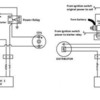
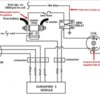
I recommend not using the OEM wiring to power the ignition, rather installing a relay to supply power directly from the battery. The wire which previously provided power to the coil (coil's + terminal) can be used to pull-in the relay. The relay then supplies power to the red wires (or red with green stripe) which power-up the positive terminal of the coil and the Duraspark module.
The wire which originally supplied the tachometer (coil's neg terminal) will need to be spliced into the green wire circuit (or green with light green stripe) between the coil negative terminal and the Duraspark module. Often the horse shoe shaped coil connector will have an additional "spare wire" attached to the same side of the connector as the green wire, specifically to provide for a coil connection.
I don't have a definite reply for you in terms of OEM wire colors, but I would guess the black wire with blue stripe is the tachometer wire. If you have a volt meter or "tester" you can verify this by turning the key to the run position, the tachometer wire will not supply power, the coil power wire will.
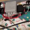
George - thank you for the response - attached is photo of my set up for which I followed your instructions and I am using a relay- now I have more questions.
If I don't use the OEM wiring to supply power to the positive side of the coil, what source should I be using to power the coil?
You say "The wire which previously provided power to the coil (coil's + terminal) can be used to pull-in the relay." If this is the case, this is what i was planning to do and I was asking whether the pink wire or blue/black wire (they are together in a two prong plug) that went into the ballast resistor then from the resistor to the coil would be the right wire to attach to the 86 terminal on the relay - please advise
Similarly, you indicate "The wire which originally supplied the tachometer (coil's neg terminal) will need to be spliced into the green wire circuit (or green with light green stripe) between the coil negative terminal and the Duraspark module. While I don't see this on your wiring diagram that I am following, this can easily be accomplished as I can add a ring terminal to the OEM blue/black wire and connect that to the negative side of the coil - Correct?
Finally, I can't turn the car on now to do any tests - it's all apart and at this point in the restoration, I am cleaning up all the harnesses and adding the Duraspark and a GM 94 AMP alternator.
I look forward to getting your insights on this - Thank you
Attachments
quote:
Originally posted by 427390:
... If I don't use the OEM wiring to supply power to the positive side of the coil, what source should I be using to power the coil ...
The diagram I posted above makes this graphically clear. A picture is worth 1000 words, etc.
quote:
Originally posted by 427390:
... I was asking whether the pink wire or blue/black wire ... would be the right wire to attach to the 86 terminal on the relay ...
The black wire with blue stripe should be the tach wire. But I "should" also be rich and handsome.
That leaves the pink wire for the other chore. But rather than taking my educated guess as gospel, I suggest you wring-out the wiring in some way.
quote:
Originally posted by 427390:
... The wire which originally supplied the tachometer (coil's neg terminal) will need to be spliced into the green wire circuit ... I don't see this on your wiring diagram that I am following ...
This is also on the diagram I posted above.
quote:
Originally posted by 427390:
... this can easily be accomplished as I can add a ring terminal to the OEM blue/black wire and connect that to the negative side of the coil - Correct ...
Incorrect. The proper Duraspark I coil uses a very specific coil with a "slip-on" horse shoe style connector. It doesn't have threaded connections, and has no way for ring terminals to connect to it. The SMP part number for the Duraspark I coil is FD477.
got it - makes sense now (and yes I have the correct horseshoe connector for the FD477 standard motor product coil) - thanks...maybe in six months or so I'll be at the stage to fire the rebuilt engine and do a road test
Thanks John - this is what I was looking for (confirmation that my pink wire replaces the lite blue wire in the diagram) - All set!
one last question for George or John - what amp fuse would you use in the new fuse holder I added?
I run a 15A fuse and have never had it blow. I believe I got that number from one of the Duraspark installation pages.
Note that it is easy to burn up a Duraspark Module (and/or coil) by leaving the ignition on without the engine running. This will occur without blowing the fuse.
Don't ask me how I know.
An ignition buzzer or light is your friend here.
Rocky
PS. Your setup looks pretty conducive to being able to test the whole assembly before you mount it in the car. Just hook up a distributor, and run a common ground from the distributor body to the mounting plate and battery minus. You have to work out the power (+) to the Solenoid and the ignition "On" relay connect (minor jumpers).
Spark plug wire / spark plug wire to the coil, and turn the distributor, and Viola! Sparkage! (Spark Plug Tip close to the distributor body).
10-4 and Thanks (and I have an MSD in another car and same thing about not leaving the ignition in the on position when not running)
Add Reply
Sign In To Reply


