Replies sorted oldest to newest

I don't know. (But I have an opinion)

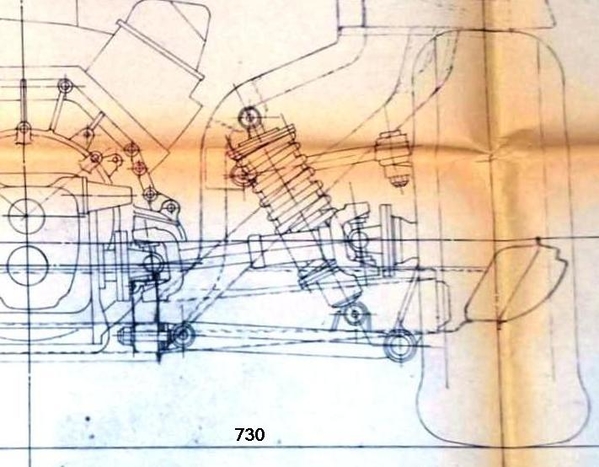
just by looking at a drawing, I would try.  

some thoughts;

Once off the floor and wheels removed, cut a 2X4 and drill so top end is attached to lug nuts and bottom resting on the floor.  I would hope the 2X4 would hold upright while removing inner long stud, then be a handle to assist swinging the bottom of the upright out of the lower arm.

I do see where the U joint might limit how far the lower upright is pullled out to allow the hollow shaft to be removed, but you should be able to lift up to reduce drive shaft angle.

NOW, how hard will it be to pull. the hollow shaft.   If it needs greasing, you can expect it to be difficult.   then poping the upper ball, disconnect the brakes and drive shaft so the upright can be worked on the bench

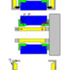
hub carrier lower S2 I6

Attachments

Images (2)
  • mceclip0
  • hub carrier lower S2 I6
Last edited by jfb05177

I have had mine out before, made new bushings (with the help of my buddy Wade Musil - S/N 4280) back in 2014.

We even put in a zerk fitting on the bottom of the shaft housing.

My guess is that the shafts are in good shape, but I am cleaning up the back end, and working the brakes, so it seems like now is a good time to take a look at it...


Rocky 

I've done it many times. Use a small floor jack to hold the assembly. Once the nuts are off you'll need a drift or something similar to drive the shaft out. Grease it up. The re-assembly is more difficult in getting things lined up. Holding those dust caps in place is challenging. 

I don't recall removing anything to do it. The brake lines are the thing to watch most. 

Last edited by rrs1

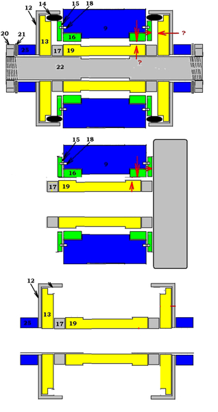
I could see making a center rod (in place of 22) that is just few thou's less than the arm spacing to hold the caps in place while swinging the upright back into the lower arm.  

then push the rod out with 22 once in alignment.

any ideal how much axial clearance in the stack of upright pieces "?"


(Note to self.   find a used long stud to make assembling rod)


Last edited by jfb05177

The assembly is all very snug as it should be. You'll be using the floor jack to raise and lower the assembly while searching for alignment by whacking the shaft end (don't damage the threads, wood, aluminum hammer etc.) and holding things in place at the same time. It's not easy, but can be done with NO special tools.

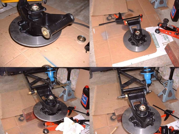
FWIW, I used a wooden dowel to initially align the amazing number of parts (especially ensuring the coated washer aligns with the pin--15&18 in drawing above). Clamped it all together as I removed the dowel. Then I slid the assembly into position on the control arm and used the dowel to align the whole enchilada before sliding the shaft into place.

Installing Shaftxx

Attachments

Images (1)
  • Installing Shaftxx

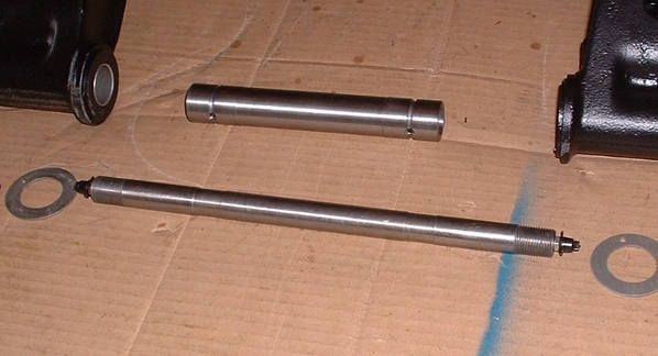
WAY back in 2004 I purchased the greaseable shaft kit developed and sold by Pantera East. As you can probably tell, the grease flows through the lower support shaft, through the lower support shaft spacer, and directly onto the bushing surface. Seemed like a great idea after having to use a small sledge hammer to get the old shaft and spacer out.

Greaseable Shaft

Attachments

Images (1)
  • Greaseable Shaft

Rlee, you got lucky. Seized, unremoveable lower shafts are/were such a common problem, Hall and others once sold a specific kit to repair the damage from condensation. Because you had to use a Sawzall to cut clear thru one or both end of the assembly to r & r a stuck shaft!  In a few cases, a 20-ton hydraulic press could not move the rusted assembly and risked cracking the cast iron upright. Some seized and ignored lower shafts either broke the shaft end or the lower a-arm. Can you say, 'Deferred Maintenance'?

That modified shaft ass'y shown (Hall Pantera also sold them) has an 0.060" drilled passage and zerk on each end to deliver grease to the two lower bushings. The spacer also got grease distribution grooves. This size drilling does not weaken the shaft appreciably. Further drillings etc can be added to complete the change-over from OEM yearly disassembly & hand greasing  to external greasing. Mine is still working after 25 years.

Tapered ball joint studs remove so ridiculously easy, I'm almost ashamed to admit it took me 30 years to find this out. You need a garage air compressor and an air hammer. You add a blunt shaft to your air hammer, get everything ready by removing the specific wheel/tire and loosening the ball joint nut (but don't completely remove it). Hit the usual pounding spot on the upright with a burst from  the air gun. The tapered ball joint shaft will be loose before you can get your finger off the trigger!

Works on front ball joints and tie rod ends, too. I have retired my 8 lb ball peen hammer.

rocky posted:

Hi RLee -

Thanks for the great information and pictures.

Question for you - how did you separate the press fit tapered shaft on the upper Ball Joint from the Upright?

I don't want to tear up my upper A-Arm with a pickle fork...

Thanks -

Rocky

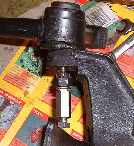
Rocky, I don't have an air hammer. So, I made up a little turnbuckle thingy, reversed the nut,  and pressed out the ball joint. I may have rapped lightly on the upright to get the ball joint to pop out once under pressure.

Ron

Ball Joint Toolx

Attachments

Images (1)
  • Ball Joint Toolx

Question for you experts... 

I am having a little trouble – I thought I’d ask if anyone has a solution…. 

Got the bushings pressed in.  Drilled for zerks.

Now, I am taking some advice from some experts, and doing a trial fit of the sleeve, washers and endcaps, but….

- The sleeve I bought (slightly extended to eliminate the thin washers) doesn’t seem to fit (I am sure the small washers are removed) – the assembly is too long.

Now, here’s the wacky part…  the original parts don't fit either!  (I checked one sleeve, etc. on both sides).

          - SO:  Either I have to really smash everything together, or….. 

                    - shrink them in the freezer?

          - machine some material off the sleeve? 

When I look at the washers, I find one is .046” thick, and the other is .036”.  So my opinion is these are shims, not “fixed dimensions” and are chosen at the factory to give you the right endplay somehow….. 

          It is still weird that I can’t get the original parts together, though.

 Any thoughts or suggestions appreciated.

 Rocky

while not an answer from an expert, this is an opinion of a ex-?

Getting the stack of the 12s, 13s, (17s) and 19 back into the a/arm is neseccary, however having a thrust clearance (end play) is needed.   I have no ideal how much that should be.  (My WAG would be 0.005")   Doing a stack of the sleeve 19 (17s) in the upright with thrust washers 15s, making it flush on one end, should have it proud the amount of the clearance can be seen on the other end.

Or just get a bigger hammer to make it fit


rear lower arm stack r1


Attachments

Images (1)
  • rear lower arm stack r1

The design of the rear upright pivot is such that to seal off weather, both o-rings in the stack must be compressed. So it may not be 'free play' that's causing your trouble. Those rather stiff outer o-rings must be squeezed a bit to get the assembly in between the lower legs but still keep water out. You do NOT want the system to just slip together! If they do, water can get in.

It's also incredibly easy to have the short locating dowel slip out of its hole in the thrust washer; if your washer(s) have a series of small dents in the bronze surface near the pin hole, they came from the washer being mis-registered during assembly. Note the bronze surface on the thick washer should be facing a solid surface; that's the function of the thin washers. Without them, the bronze side of washer should rub on the smooth surface of the upright.  When I tear miy uprights down, it takes pry bars and a 12" c-clamp to force the parts back together. ******* grease helps.

Add Reply

Post
×
×
×
×
Link copied to your clipboard.
×