Morning all,

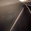
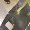
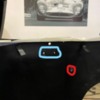
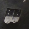
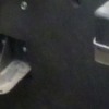
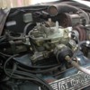
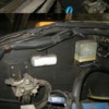
just mocking up the engine bay insulation. Unsure of how the coil was originally mounted? I've highlighted 2 holes in the body in blue where I think it's mounted, looking like it would have to face downwards? The hole marked in red is where it was fitted.

Also, I've got the heater valve bracket fitted on the LH, near the expansion tank. I've noticed on photos from Leea, and another car that the bracket is on the RH. I've rivets where it could be mounted, and the cut out on the original insulation. The bracket is riveted on, and looks period.

Someone in the past had mounted the valve in the front tub area, with a cable attached to adjust. Where does the original cable go?

All very confusing! Thanks in advance as always!

Attachments

Images (4)
  • image0 (6)
  • image1 (4)
  • image2
  • coil_LI
Original Post

Replies sorted oldest to newest

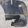
Hi Chris, while my car used that same coil mounting location (red hole), there doesn't seem to be much consistency between cars.  I attached photos of my original insulation to show the indentations left by the coil bracket. The 'blue' location in you photo seems more logical, which - - IF my bracket is correct - - would put the coil right next to the voltage reg, and as you suggest probably require mounting the coil updside-down.

Picking through several dozen marginal photos I did find a few cars showing that upsidedown configuration.  That said, there seemed to be at least as many examples with the coil upright, but located further to the rear of the car, ~3-5 inches behind the voltage reg.  (Unfortunately none of the photos clearly show the mounting holes used, or details of the bracket).  There were a few other examples using the 'red' hole, but with the coil mounted diagonally, at various angles.  And finally, 8MA566 and 8MA632 check in with the coils on the LH side (!!), in what appears to be a consistent location. I ASSUME they were both modified, maybe by the same shop?!

Does anyone recognize the bracket illustrated in image #3, or have more definitive coil info?

Water valves are easier....should be one on each side, in identical riveted brackets.  No cables were fitted...opening/closing valves was a manual operation. Must have been one of those corners cut as the car was rushing to production


Attachments

Images (3)
  • image1
  • Goose 1010 insulation OEM detail e
  • IMG_0916 (1)
Last edited by nate

Chris and Nate, the coil was Ford (designated in the parts book), yes the placement there on the right (with the HV coil wire taped up in the harness). Nate, the impression on '1076 is (literally, the impression in the bitumen board) is the same as yours that the bracket for the coil had one screw and was rotated so the coil faced Up. See also 1046, though rotated the original impression is there.  https://pantera.infopop.cc/top...435#1598208419866435

  Coil bracket on 1076 also looks like yours..

Agree, no cable on the heater valves. Chris, that is plural, there was one each left and right--both the easy to find Giulia valve. The brackets are riveted on.

Attachments

Images (3)
  • 8ma1076 right bitumen board
  • heater valves left and right
  • driver side bitumen insulation
Last edited by leea

Chris, good news, not too difficult to make....Here is what the right side looks like. Honestly a perfect copy of the one on the left side would be better than what is on the right--at least, the direction of the exit hose just seemed backwards any logic...

More motivation; at least this Alfa bracket is all wrong... https://www.alfabb.com/threads...ng-my-heater.628737/

and the part here; https://autofilippos.com/produ...lationcontrol-valve/

  ! Lee

Attachments

Images (2)
  • left bracket for heater valve
  • rh bracket
Last edited by leea

Add Reply

Post
×
×
×
×
Link copied to your clipboard.
×