Replies sorted oldest to newest

quote:
Originally posted by daleyracing:
...Hopefully George will come through, I know he will, (I Hope)...


thanks for the vote of confidence! LOL ......

Dennis the oem wiring routes the power for the fans through the ignition switch. This is not good. So my advice would be to not put your wiring back 100% oem. My questions are (1) does your car have the oem fans, or aftermarket fans? (2) will you use the oem fan relays, or aftermarket relays? (3) are you using oem style thermostat switches? (4) if not what type of switching is used for your fans?(5) do you still want an oem wiring drawing, or would you prefer a drawing that eliminates the shortcomings of the oem wire harness?

your friend on the DTBB
Dennis,

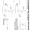
Here's the requested wiring diagram for revising the radiator cooling fan circuit.

This wiring revision will eliminate the problem of the motor continuing to run with the ignition switched off .

Notes:

The pink wires attached to fuses 11 & 12 at the fuse box can be cut & shortened to whatever length is required to reach where ever you decide to mount the new relays. The remainder of the wiring to the oem relays & fan motors is from that moment on dead and can be cleaned up or eliminated.

The drawing for the new relays is based upon the DIN style SPST, normally open (NO), 12 VDC automotive relay such as those manufactured by Hella or Bosch.

You'll need 2 new relays & 2 new fuses to do the job, plus 3 different gages of bulk wiring and the proper connectors. The circuit from the battery connection (between the ammeter & the ignition switch) should be a minimum of 10 gage wire. The individual load circuit for each fan should be a minimum of 12 gage wire. The wires connecting the relays to the temp switches is not as critical, 16 or 18 gage will do in that application.

I apologize for taking so long.

Your friend on the DTBB

Attachments

Images (1)
  • Pantera_fan_circuit_revision_diagram
Last edited by George P
George,

There are a number of drawings, articles and kits for the fan mod floating around. One published by Mike Drew, Terry, etc, some better than others. There are some variations on the wiring depending on the year and in fact on my 71 car the fan run current load did not go through the ignition switch. I did add relays near the fans because the 71 cars had the fan relay mounted on the relay panel under the dash.

From a safety standpoint and to prevent the possibility of my car burning to the ground, any of the relay mods I’ve done I’ve located the fuses on the power feed side of relays. This is especially important when a relay has ground potential on one of the terminals. In your drawing that potential is through the temp switches. I’ve had relays come apart internally and if there is a ground potential available you can have a direct short to ground resulting in maximum smoke and then fire. If nothing else the melted wire insulation causes a big mess makes and your car smell bad. Not a big deal unless the relay comes apart but I’ve had that happen a number of times with OEM relays on other cars and electronic equipment.

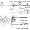
On the drawing posted by Larry you can see that the factory was mindful about the fuse location but not so smart about the ignition switch load.

Mike
Last edited by pantera1887
Since we are looking at all these diagrams, now might be a good time to point out how our cars' system pull all their power THROUGH the ammeter!!

This is why it is so important for the connections on the ammeter to be checked and kept tight and solid. High amperage and loose connections equals heat equals funny smells equals bad things happening. Frowner

Next time you are wondering what else needs to be done, pull your gauge panel and inspect those connections.

Larry
Post
×
×
×
×
Link copied to your clipboard.
×