As requested by Comp2 here are some details of the changes I have made to my Pantera’s cooling system.
It gets real hot here in Perth, Western Australia so some changes were needed to cope with the 45 degree C summer heat.

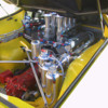
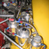
The original expansion & swirl bottles were discarded.
These components re-manufactured in alloy & shifted to the rear of the engine bay so re-filling of coolant, radiator cap etc can be easily accessed.
Also shifted to the rear is the thermostat for two reasons.
The original thermostat, (even the Robert Shaw type) is fairly restrictive & hinders coolant flow.
As well as being difficult to access if it requires changing, the seats, bulkhead plate etc all have to be removed to get to the front of the engine.
So now the bypass hole in the engine block where the original thermostat was located is blocked off & the thermostat removed.
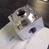
A new alloy housing was machined up to house a large Mazda truck bypass type thermostat which has three times the flow rate due to its increased diameter.
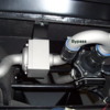
The bypass “warm up” circuit is still active & circulates from the old thermostat outlet to the new thermostat & a bypass -10 hose feeding back to the water pump.

There are now three coolant bottles.
A swirl bottle, a header bottle & an expansion bottle.
The main flow of hot coolant exiting the engine goes via the remote thermostat housing, then to the swirl bottle, out the bottom of the swirl bottle, then through a 55 gal per hour electric water pump, then to the radiator via 38mm stainless coolant tubes.
There are two small -4 vent tubes from the front of the cylinder heads that feed into the header tank as well as a -4 vent tube from the top of the swirl bottle to the top of the header tank.
The small header tank is the highest part of the cooling system.
There is a -10 hose from the bottom of the header tank feeding the mechanical FlowKooler water pump on the front of the engine.
There is a -6 hose under the radiator cap that feeds the expansion bottle which is the normal coolant expansion system that most cars have.
The swirl bottle has a Zinc anode screwed into its base to try & minimize corrosion in the components.
All three bottles as well as the remote thermostat & back up pump are rubber mounted.
Both the remote thermostat housing & the Swirl bottle have filling points.
The electric water pump is switched on by the Motec when the system reaches 95 degrees C, it gives an added boost to the coolant flow when temperatures start to rise.

The radiator started life as an Aluminium PWR made high flow three core.
We made our own header tanks each end & made the radiator a double pass to keep both main hoses on the right side.
Radiator is tilted forward 45 degrees to try & maximize radiator height.
There is a bleed fitting on the top radiator hose made from a brake bleed screw.
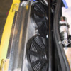
The radiator is fitted with twin shrouded sucker electric fans to the rear, which are switched on at 85 degrees C via a temp switch located in the hot side of the forward coolant tubes.
The radiator also has a screw in zinc anode to the left side tank to minimize any radiator corrosion.
The system is very easy to fill & bleed.
Filled from the swirl bottle & header tank, turn on the electric back up pump & it circulates fluid around the whole system, (engine does not need to be started).
Bleed off trapped air from the bleed point up front & at the thermostat housing bung.
System takes a huge 18 litres of coolant.

Regards,
Tony.

Attachments

Images (1)
  • Engine_1
Original Post

Replies sorted oldest to newest

Radiator installed.
The small blue bung on the left side is where the zinc annode screws in.
Radiator is rubber mounted top & bottom.
You can just see here the bleed point on the top hose on the right side.
All hose connections throughout the car are with fibre reinforced silicone hose & stainless band clamps.

regards,
Tony.

Attachments

Images (1)
  • Radiator_copy
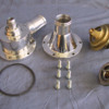
Thermostat housing components.
Picture shows both the old Cleveland thermostat & the new Mazda truck item for comparison.
The Mazda truck thermostat opens at 85 degrees C.
You can see here the Mazda thermostat has a plunger to its rear, just like the Cleveland item.
When installed in the housing it covers & uncovers the -10 welded on fitting you can see on the housing.
This fitting with matching -10 hose returns hot fluid back to the Flowkooler pump & recirculates through the engine & back to the thermostat housing.
In most driving situations the car stays between 85 & 90 degrees C.

regards.
Tony.

Attachments

Images (1)
  • Thermo_parts_copy
Last edited by edge
Your thermostat housing is gorgeous. I bought a bypass from IPSCO which was also beautiful Problem was the thermostat was a traditional thermostat but even more a problem, the bypass is not blocked when the thermostat opens.

I made a 2- thermostat bypass. Problem with my construction is how I built it makes it near impossible to seal which means I will be building another.
Autotrend EFI (www.autotrendefi.com) has a bypass style remote thermostat housing that uses a BMW V12 thermostat. It also has 1 3/8" in/out/bypass pipes to match the Pantera's coolant pipes. They chose that particular thermostat because it is a true bypass style thermostat (with a bypass block-off "hat") and has the largest orifice of any readily available thermostat. It's available in a number of different opening temps too. The photo below shows the prototype unit before the in/out/bypass pipes were welded on.

If you don't want to spend that much money, you can always use an early '80's BMW 318i/320i bypass thermostat. Many Pantera and GT40 owners run this thermostat and are very happy with it. It won't flow as much as the Autotrend unit but it's a fraction of the price too.

Attachments

Images (1)
  • 100_2910
Here's a photo of the Autotrend EFI remote thermostat assembly installed in the front of the Pantera with a Stewart electric waterpump, that's used as a booster pump.

I decided to go with the Stewart pump because it creates zero restriction to flow when it's not running. That gives me lots of options as to when to have it running. Some electric water pumps won't allow any coolant to flow, unless they're "on", which means they have to run whenever the engine's running.

Attachments

Images (1)
  • Installed
Last weekend I had to remove the radiator as it had a tiny leak that was becoming anoying.
Draining the fluid was a task as there were no drain points other than just removing a hose clamp & letting it squirt out, a messy business when trying to save the coolant.
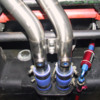
So after the radiator was repaired we fitted a couple of drain ports in the forward stainless tubes.
Seen here with blue recessed 1/4" NPT bungs.
Much easier to drain the system now.

regards,
Tony.

Attachments

Images (1)
  • coolant_drains
Thats a great idea for the heater supply.
I may need to do something similar if I ever re-connect the heater.

Don't really need a heater here in Perth as it does not get that cold.

In regards to the check valve, the red check valve in the picture is an Earls item, this hose sucks from the Vacuum bottle, which in turn sucks from the brake booster which has another check valve.
In all I have three check valves in the brake system as I also have an electric vacuum pump sucking on the vacuum bottle via the third check valve.

regards,
Tony.
I looked at that check valve. It was intended for fuel system but I thought it may work for the application you are using.

I ended up getting some plastic check valves from McMaster. I will see how they do or hold up.

I bought the BMW bypass valve and did not like it. I considered making another bypass valve but after much thought I decided not to for the time being. Since the Cleveland and the 400 (which I have) are using an internal bypass which works relatively well I decided just to go with that. It would be something I could easily change latter if I decide to.

I am doing a few things a little different. I am one hose segment from finishing the coolant lines.

I am not really using a swirl tank. The high point in the engine outflow tube is ported to the bottom of the expansion tank. The pressure cap on the expansion tank goes to the puke tank. In the photo I am just waiting on my final hose and my thermostat to button it up.


In addition, in the tube which is the high point I have another fill cap. In the top of this fill cap I have a float controlled air bleed. This is something I am trying. We will see if it works or is a problem.

It comes from heated floor systems and I can tell from using it in my heated floor it purges air very well.

I expect it will help purge the last few air bubbles in the end when the manual purging is done. I expect it to work best when the engine is cool and UN-pressurized. It has a float inside. It flows air till the water raised the float and closes it off.

I expect each time I run the car it will likely purge a little air during the initial part of the run.

There is a hose fitting braised onto the cap. This hose fitting will go through a check valve to the top port on the puke tank.


Post
×
×
×
×
Link copied to your clipboard.
×