Replies sorted oldest to newest

I actually don't know if the a/f is too rich.

You don't tune Webers that way, i.e., like fuel injection. You keep feeding it fuel until you don't get more power.


There is no intermediate circuit. The idle circuit hangs around until the mains come on line around 3,000 rpm, then they both run together.

You can see the black smoke kick out of the exhaust of a car in front of you when they hit the throttle.

Reading the plugs with them can be a challenge but Shelby established a jet size on the dyno on the 289 Cobra engines.


The idle circuit was/is very heavy. Much like a Holley 4179, 750cfm "double-pumper" carb is.

Basically, smarting your eyes at idle.


You can lean them out now due to more idle air holders/correctors being available but they will never be know as "environmentally friendly".

If that's the kind of engine you want then computer controlled electronic fuel injection is the only way to achieve that but frankly from what I have seen, these carbs seem to make more power but their big deal is the throttle response particularly coming out of corners. It's a little difficult to explain. You need to drive the car to understand entirely.

You can not compare carburetors to electronic fuel injection. One is analog and one is digital. A carb can not be tuned for every 100 rpm differences. FI can and is.


Fun to drive? Sure. Any car with over 500hp and almost 450lb-ft of torque is fun. That's really big block territory.

It's a real 12 second 1/4 mile car too.


I just posted this to show everyone a plus 500hp stock block, iron head Cleveland.

Something some say doesn't exist, only does in someone's fantasy world or isn't streetable? This engine and car are very streetable.


I know this car and it is down on power from what it was originally at because of the cam change to a "Weber cam".


Of course to seriously go racing in "vintage" and be competitive you still need to find about another 100hp.

This engine would run at best in the middle of the pack at this point in time.

The front runners are making 620 to 650 BUT at 8,000rpm.


So you'd have to tune this engine to that, 8,000rpm on the dyno. Of course then you'd kill the durability and life expectancy would probably become nil?

Clevelands can keep making power up the rpm band but it would need more cam and the carbs tend to get restrictive around 6,700rpm or so in that bore size. Probably a "NASCAR" type cam with lifts in the .700-.750 range to gain the upper rpm power band?


As it is, this engine is PROBABLY pretty much what you should have found in a Group 4 Pantera but these dyno numbers are much better then the previous dyno numbers from one of the original vintage Detomaso factory race cars I posted previously.


That one topped out at around 450hp and 380lb-ft of torque.

I don't know why but maybe they needed someone from New York to go tune the thing for them? That is where this engine is from.


That Detomaso engine came from the Bud Moore shop too? So much for North Carolina know how? Beats me?

Maybe Bud Moore didn't want to supply them "I-talians" with a competitive engine? Those guys can be funny like that?

On the surface, it would seem that they didn't know what to do with an American engine in Europe I suppose back then? That logically shouldn't be the answer though?


There certainly isn't any black magic in this engine. It's as basic as it gets with the exception of the Weber carbs and it is making around 100 more hp and torque then the factory and Moore could get out of it, AND they were using 180 degree headers to boot.

Something was not right in Modena for sure back then? Maybe just way to early in the engines racing development timeline history?
Last edited by panteradoug
He's tried several cams that I know of.

The one that I knew specifically was by CamTechniques. I have a copy of the timing card somewhere but I'd have to search for it.

I don't recall if it was a hydraulic roller though.

I do know that it had 28 degrees of overlap and was around .580 lift. Around 282 duration.

Compcams WAS selling a "Weber cam" for the Cleveland also but I don't remember seeing it recently on their web site?

You could check yourself there for that info?
Last edited by panteradoug
I actually expect that this cam is no longer a stock item or maybe even being offered at all?

It may still be listed on the "Inglese" site that Holley bought out.

I can't swear to identical timing events on them. There were lots of complaints about the lack of "crispness" with it or maybe more correctly stated, the loss of crispness from what was in the car before.

There definitely is truth to that. I always thought it was an 80 to 100 hp loss but never dynoed a before and after. The reality is it is much more likely that it is down 30 or 40 hp with the 114 center vs. a 110 but that is pure speculation on my part.

It's kind of hard to complain about 539hp particularly when you see how smooth this engine runs on the street.
Sounds like the cam, yes, with the .586 lift.

The timing events are juggled so that in effect the overlap is about 28 degrees.

That seems to be the number necessary to reduce the blow back through the carbs.

There is another way to do that if you can use the tall 5" velocity stacks? There you can use whatever overlap cam you like.

With the tall stacks the vapor cloud hovers within the stack itself, not spreading all over the engine.

With the short stacks on that particular engine application in that car and the close proximity of the stacks to the inside of the hood that was not possible.

The Weber cam was really developed so that you could use an air filter over the carbs without them getting soaked in fuel and thus removing the fire hazard.
The duration at 0.006 (aka the advertised duration) is not given for the "Weber Cams" in Gary's link. But the hydraulic intensity of most hydraulic roller cams is 54° or greater, so the duration at 0.006 can be reasonably estimated.

*ESTIMATED duration at 0.006 inch tappet lift = 278°/280°
Duration at 0.050 inch tappet lift = 224°/226°
Gross valve lift at 1.73:1 rocker arm ratio = 0.578/0.571
LSA = 115°; overlap = 49°

As per the dyno sheet this engine is churning out 539 horsepower peaking at 7000 rpm. The original claim was that this engine is equipped with this Comp Cams Weber Cam. If so it is further proof, if any is needed, that a Cleveland with 4V heads does not need long duration or lots of overlap to make plenty of horsepower or to rev at high rpm.

quote:

Originally posted by René #4406:

115 ° lobe separation, it seems to me that this is the value George recommends for a street engine?


René I used to advocate 115° LSA, but in the last few years I've switched to recommending 114° in the hope that folks will encounter less resistance from the cam grinder. There are still folks at Bullet Cams who contradict the cams I pen, claiming they won't rev as high or make the horsepower I say they will. Despite their claims for being familiar with the 351C 4V, they obviously aren't. If you're going to get a cam ground to specs like these, a person has to be capable of standing firm with the cam grinder.
.
Last edited by George P
This explains it.

http://www.4secondsflat.com/Cam_Design.html

It's written by Harvey Crane.


There is a thread running at SAACforum.com where an owner of a CSX3000 427 Cobra posted the dyno numbers of his '67 427MR engine.

It topped out at 430.5hp@ 6100 and 415lb-ft@4900.

I mention this just to put into perspective the significance of this 351 Cleveland dyno that I posted.

One can draw their own conclusions. Cool


When I find the cam specs on the Cam Techniques cam I'll post them here. So far I don't know where I put that sheet?

I do remember it as being very similar to the CompCams but the sheet does show the timing events as I recall?
It would be best if the cam grinders publish the lift curves. I have never understood why they do not do it, I know that they consider it to be their Know How but it is false since it is possible and easy to take these curves.

In addition it would allow to calculate the clearance between the piston and the valves and calculate the depth of relief valves without having to do a lot of tests.
quote:
Originally posted by René #4406:
It would be best if the cam grinders publish the lift curves. I have never understood why they do not do it, I know that they consider it to be their Know How but it is false since it is possible and easy to take these curves.

In addition it would allow to calculate the clearance between the piston and the valves and calculate the depth of relief valves without having to do a lot of tests.


The procedure for determining piston to valve clearances is a standard/known procedure.

You don't calculate it, you measure it with clay.

For safety a "standard" number is used. I think it is .080" on the intake, .100" on the exhaust.

US pistons are all made with those considerations and you don't get close until you are around .650" lift.

So that really puts the "Pro Stock" and NASCAR type engines in danger with .700+ lifts.
quote:
Originally posted by PanteraDoug:

The procedure for determining piston to valve clearances is a standard/known procedure.

You don't calculate it, you measure it with clay.

For safety a "standard" number is used. I think it is .080" on the intake, .100" on the exhaust.

US pistons are all made with those considerations and you don't get close until you are around .650" lift.

So that really puts the "Pro Stock" and NASCAR type engines in danger with .700+ lifts.


We are obliged to measure it with clay because we do not know the lift curve, if this curve is known it is quite possible and easy to calculate it is much faster than to measure it with the 'clay.

When building a motor with a stroke, a rod length, a compression height and a custom compression ratio, we can not be satisfied with the "standard" calculation rules, it is essential to check.
Last edited by rene4406
I know the clay, the light spring, the lead wire, the preload, advance and delay the camshaft, etc, etc ... but they are all empirical methods that require to mount a head, try, disassemble , back, etc ... and especially you have to have pistons.
When we know the lift bar, we can know the distance valve relative to the piston for each degree of crankshaft using a simple spreadsheet Excel, it's still more convenient and it allows to machine the relief valves by the piston manufacturer before it delivers them.

But the real subject is the comparison of camshafts between them and it is impossible to do it really properly without having lifting curves.
quote:

Originally posted by Gazoz:

George could you please explaine the hydraulic roller cam intencity number.or if you already have in the past just direct me to were i should be?


It is the difference between the advertised duration and the duration at 0.050. It was conceived by Harvey Crane as an indication of a cam lobe's ramp rate. For most cam companies the advertised duration is measured at 0.006 tappet lift, it is supposed to be a standard that everyone adheres to. Hydraulic tappets are supposed to "lock" and start moving the valve after the plunger has been compressed 0.005 inch. So duration at 0.006 is a good indication of actual valve movement. But Crane (and others) has cams out there that are measured at 0.004 tappet lift. Measuring advertised duration at 0.004 tappet lift adds 8° to 10° to a cams advertised duration figure, it makes a cam look way bigger than it actually is.

In the 1970s hydraulic flat tappet cams had hydraulic intensities in the 65° to 70° range. Valve springs had 90 pounds seated force to prevent valve bounce. Today hydraulic flat tappet cams have 50° to 54° hydraulic intensity (some are faster yet) and valve springs have 115 to 130 pounds seated force. The cams in question, hydraulic roller cams, have 54° to 56° hydraulic intensity (occasionally I run across a lobe with 52°). I added 54° to the duration at 0.050 to arrive at my "estimated" duration at 0.006 figures.
Last edited by George P
quote:
Originally posted by René #4406:
And if I see that there is not enough clearance, what do I do? I deposit the head, and I dig valves relief ..... if there is enough margin with the top ring.

But I agree, the weak spring is more practical than the clay.


How are you going to change the weak spring to a triple spring without taking off the head?
You are going to use air pressure to hold them on their seats?
Good luck with that. Wink
Only one piston is mounted to check the valves clearance, so the head must be removed and then the final assembly done.
To temporarily mount a cylinder head and to deposit it, it's fast, the difficulty is to modify the pistons if the control isn't good, that's why it's better to know the valves lift curves before ordering the pistons.
All you need to know is the clearance at maximum lift and the piston at top dead center.

The valve is no closer to the piston at any other point. You don't need to know the clearances at any other point so what is the point of graphing the lift "curve"?

I don't get it?


Unless you are using piston blanks from another engine or machining them down out of a solid piece of aluminum billet, ALL pistons are going to have the valve reliefs cut into them.

The manufacturer can tell you the maximum lift of the cam that you can use with them before you need to flycut the valve reliefs.

Even so, that usually is because you are going to a much larger valve outside diameter then the enging ever was built for.
I do'nt agree, the minimum clearance may occur a bit before or a little after the top dead center, I checked it on other engines where I was using a camshaft with a lot of overlap and very fast openings and closures.

Anyway, I never asked how to check that, I know how to do it, I just said that having the lift curve facilitates this check.


My subject was above all the supply of lift curves by cam grinders in order to really compare camshafts with each other.
quote:
Originally posted by PanteraDoug:
I have never seen a graph of a cam lift.

The closest clearance is at maximum lift at the highest point the piston is at, unless you have invented a new form of physics?

I suppose in this era of alternative facts anything is possible? I must live in an alternate reality? Wink
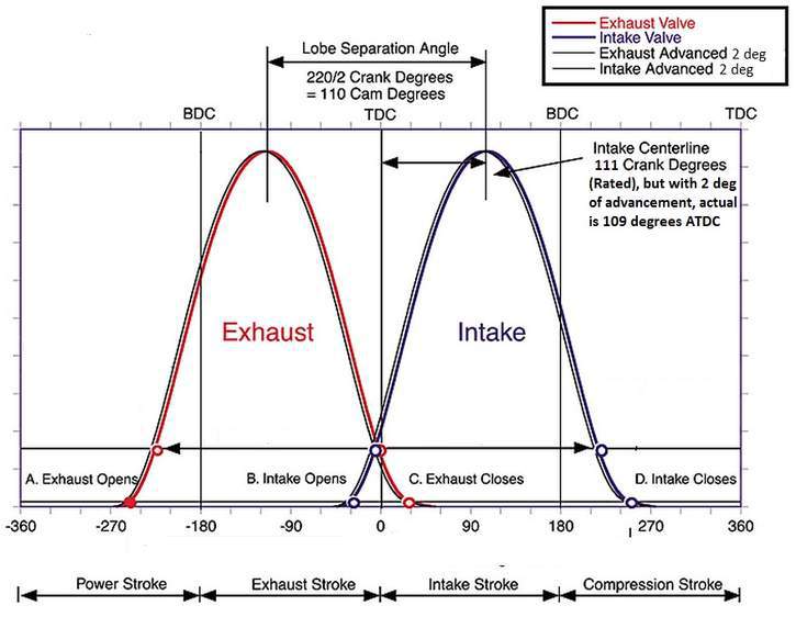


No need to invent new laws of physics, it is enough to well understand those that are known and particularly those of kinematics.

To determine the clearance between TWO moving parts we must take into account the position of BOTH parts and therefore not only that of the piston but also that of the valves!

Therefore, the minimum clearance is not necessarily at the top dead center simply because the valves, during the few degrees before and after the top dead center, can open or close faster than the piston goes down or up.

I do not live in an alternative world but it is not the first engine that I rebuild by modifying it and I never affirm anything without being absolutely sure of it. I also avoid making fun of people when I know badly what I'm talking about.

If you've never seen a lift curve, it's that you still have a lot to learn about engines.
It simply doesn't matter. The closest possible place the piston can be to the valve is at maximum lift and the pistons highest point.

You need to maintain .100" clearance on the exhaust. .080 on the intake.

If the piston is on it's up stroke still .250 down in the bore and you happen to have so much duration on the cam that you are at maximum lift there, great, you have .250 more clearance there, which again, doesn't matter.


Listen. I'm the original poster. If you guys want to debate this crap, go start another thread and get it out of here.

You want to talk about derailing a thread, this is a perfect example.

WTF, does this have to do with the dyno chart that I posted here?


While you are at it, go debate how many angels can sit on the head of a pin? Oh and look out for the pin. It's a little sharp.
If I may comment.

The dwell period occurs from about 30° BTDC to 30° ATDC. There is very little piston motion during the dwell period, the pistons are as high in their bores as they can be during the dwell period. Unlike the reciprocating motion of the pistons, the cam rotates at a consistent speed, thus the valves are in motion during the dwell period even though the pistons' motions have ceased. Since the valves are in motion during the dwell period, the clearance between the valves and the pistons is in a continual state of change during the dwell period.

The exhaust valve clearance should be checked as the piston finishes rising in the bore from about 30° BTDC to about 10° BTDC. The intake valve clearance should be checked as the piston prepares to descend into the bore from about 10° ATDC to about 30° ATDC. That's all the clearance that ever needs to be checked, from the mildest street engine to the hottest race engine.

Piston to valve contact normally occurs when the "closing" exhaust valves float, because the pistons chase the exhaust valves as they close, so this clearance is the more critical of the two to check ... and this is why we normally expect more clearance (0.100 inch) at the exhaust valve. The intake valve clearance is not so critical because opening intake valves don't float, and because the pistons are "fleeing from" from the opening intake valves.

Doug I would have commented about hijacking the thread but you've been right in the middle of the comments being made regarding piston to valve clearance. So long as you were commenting I assumed the hijacking met with your approval.
.
Last edited by George P
YOU derailed the post:

quote:
Originally posted by PanteraDoug:

The procedure for determining piston to valve clearances is a standard/known procedure.

You don't calculate it, you measure it with clay.

For safety a "standard" number is used. I think it is .080" on the intake, .100" on the exhaust.

US pistons are all made with those considerations and you don't get close until you are around .650" lift.

So that really puts the "Pro Stock" and NASCAR type engines in danger with .700+ lifts.


And I tried to "refocus":

quote:
Originally posted by René #4406:
I do'nt agree, the minimum clearance may occur a bit before or a little after the top dead center, I checked it on other engines where I was using a camshaft with a lot of overlap and very fast openings and closures.

Anyway, I never asked how to check that, I know how to do it, I just said that having the lift curve facilitates this check.

My subject was above all the supply of lift curves by cam grinders in order to really compare camshafts with each other.


But George agrees with me, we have to check a bit before and a little after the top dead center, not just at the top dead center.


George, do you know why cam grinders usually refuse to communicate the lift curves?

Add Reply

Post
×
×
×
×
Link copied to your clipboard.
×