I'm making up a new line due to Wilkinson not having one in stock. Looks like the O.D. is around 5.90 MM and of course my local auto parts store didn't have any metric sizes. The standard copper tubing size they had was about .030 bigger. If I can get the fitting to go on there can I use that?
Replies sorted oldest to newest
Donny,
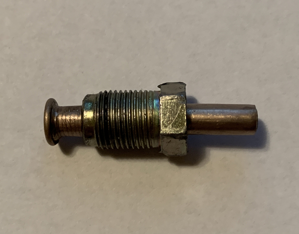
I am in the process of doing the same thing. The car I am currently working on came with no clutch hard line at all. I was able to source the metric tube nut that goes into the clutch master. I am using .25" copper nickel tubing for the section to the engine bay. I test fitted the tubing into the nut and it fits okay and is a little on the snug side as your measurements suggest. Here is my test setup.
Attachments
Its been quite a while since I looked at the extension piece line, but wasn't that 2 ft. extension line a flexible plastic line? I bought my car brand new at a Lincoln Mercury Dealer in March of 1975. I'll take the car cover off and take a look and see what I have. I don't ever remember replacing this piece. Adjusting the clutch properly with about 0.040" clearance between throwout bearing and clutch pressure plate fingers allows for maximum release travel and takes pressure off the line when clutch is fully engaged, but must arm stop must be reset occaisionially as the clutch disc wears. Ignoring this proper adjustment can result in preloading causing the clutch to slip.
How long of a piece did you use? The only stuff I can get at the auto parts places around here is 60" so, I was thinking of adding a coupler to make it a little easier going up thru the front trunk. I know, one more place it might leak. I just routed new brake lines as well. The lines were made by classic tube and all of them took a bunch of monkeying around with to get em to fit, they were in the ball park though.
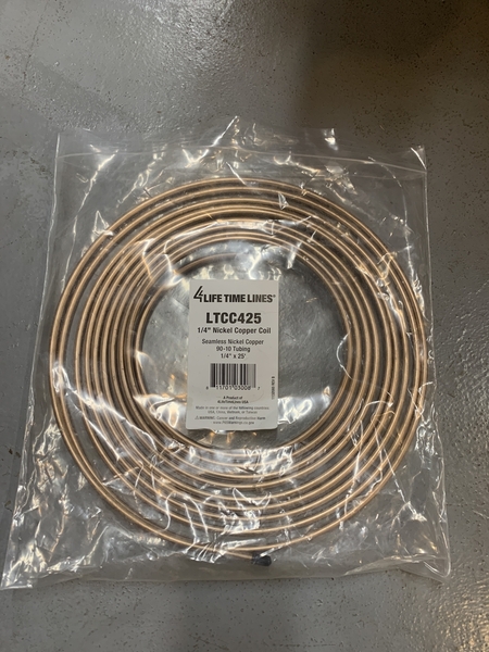
I got the 25' roll. It is on Amazon for $29. I also keep a roll of 3/16" on hand for the brake lines because I have been working on several Pantera concurrently. For the straight lines I recently bought some copper nickel from Zoro.com for not much money.
Attachments
Petematus, I was just eyeballing the distance at the pressure plate and it looks to be at least .040 or more, I haven't stuck a gauge in there yet. Every thing is new and has not been tested yet. how much petal play do you run? Is it best to adjust it at the pedal/master or the slave or a combo of all? And positioning actuator arm, how do you know where to clock it? Before I redid everything I couldn't get it to adjust right (probably due to it being shot). I'll see how it acts when it get it bled.
I just got a lifetime supply too! Thanks for the info.
You do not want to run a solid line from the chassis to the slave cylinder. The vibration and motor movement will eventually fatigue the tubing and result in a failure.
you need a flexible line
Larry
Great point on using a flexible line from the chassis to the clutch slave cylinder!
I posted a clutch adjustment procedure under topic "CLUTCH ADJUSTMENT INSTRUCTION" back in March of 2021. This procedure, if not done right, can result in clutch not fully releasing and resultant expensive ZF syncro repair/failure. Original adjustable stop bolt and slave cylinder spring must be used. They are there for a reason.
Call Dennis at Pantera Performance Center in Colorado. He has a stainless flex line that is the right solution for this.
I think he is wanting to replace the existing hard line with a new one and not the flex line.
Yes, I already got the flexible line.
For clutch hard lines use 1/4” OD tubing. If you use seamless stainless steel tubing and AN fittings, you only need to single flare the tubing. I’d forget about the plastic flex hose that goes between the hard line and the slave cylinder and use -4 AN Teflon lined braided SS hose. The hardest part of putting this together will be figuring out what fittings you need for the clutch master and slave. The rest of the fittings will be steel or stainless steel -4 AN.
The only fitting I reused is the one at the end of the hard line and the start of the flex line. I bead blasted it and then had it cadium plated.
For brakes, we never use copper tubing because it work-hardens under each foot-press, and often cracks. But that's under about 1100 psi from the power booster to the brakes. For the clutch, the pressure is only 2-300 psi so copper tube will work safely. And the difference in OD between U.S copper and Euro is small enough and the pressures are low enough that running the proper drill thru a stock bubble-flair fitting should re-size it well enough. Never actually tried it, though. All my flex lines are Aeroquip braided stainless.
On the bell housing end, there's a metric thread 3 way junction that attaches the red plastic flex line. Those stock threads are sufficiently close to SAE dash-4 that a std dash-4 AN fitting will screw right in. I add a flurocarbon o-ring as insurance. Then you can use SAE braided stainless line up to the slave cylinder. Most slave inputs nowadays are threaded SAE 1/8" NPT (or can be made so). So a 1/8 SAE NPT-to-dash-4 fitting will connect the other end of your stainless flex line. After 50 years of soaking in brake fluid, I'd expect the stock red plastic line to be very stiff and brittle, maybe ready to vibration-crack.
For the benefit of the next caretaker of your car, I suggest painting any altered fittings like this red or yellow if you ream the euro fitting for SA line size. And jot down such changes in an "As-Built" notebook that should always stay with the car. It's hard enough to sort one of these things out when the former owner is still around to answer questions. That's not a 'given' any more....
Jack,
I have been using nickel copper (not pure copper tubing) for the brake hard lines and now for the clutch as well. It is not the same as copper tubing and I agree that it would be unsafe to use plain copper tubing for brake lines. As far as I know, nickel copper does not have the issue with work hardening and it is DOT approved. Are you aware of any issues with nickel copper for brakes?
Actually, I'm completely unfamiliar with using nickel-copper line for anything at all. I must be old-school- what is its advantage over steel? Do any race teams use it? Is it easier to form?
It is very nice to work with. You can form it by hand. The double flaring tool works well with it and the flared ends produced with it seal correctly. I prefer it over plain steel. I don't think I could accomplish anything with stainless tubing. The nickel copper tubing also looks nice and does not corrode.
I was at a shop recently that specializes in hydraulic brake and clutch lines primarily for racing applications. He said he only works with stainless because that is what his customers request.
as I did replace ALL brake lines I used Werkstoff: CuNi10Fe1Mn
90 % Kupfer und 10 % Nickel, Ø 4,75 x 0,78 mm (hope the dia measures are correct - if needed I go in the basement for a doubble check), called CuNIFer (smile)
Is "supposed" to be approved and I had no issue on the picky German TÜV.
Advantage as above is easier to work with, used a simple tool/"plier" to bend it and a simple tool to "fix" the ends (if foto need I go in basement). At the rear neer the gear box the circle is very small so needed some tricks to do it..using a tube of adeq. diameter and slowly and slowly bendt it. .. and got it tight after def 3 attempts.
also as the material is a bit softer it is easier to make the connection tight..which is not easy..see picture above with the "fitting" looking pretty much used. You need the very correct tool to tighten it think is 11, 12 13 mm..!! There are tools with a small opening to fit the tube more like a ring tool. I use those. Works also nice on the clutch line I had more problems which is ORIGINAL Cupper, but make it tight took me a while altough less pressue (TX Jack, did not know that, although expectable).
Well as also above you might move to int. versions per adpter..which I do not like on Brakes as any more links increase the risk of failure.
Matthias /Böblingen Germany
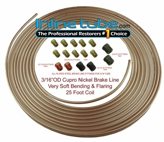
FWIW, This is what I used to make brake lines that run from the shuttle valve to a new Wilwood Brake Master. Easy to double flare and bend and even came with the fittings I needed. Plenty of tubing to practice flaring and bending a few times since it had been a long while since I previously made up any brake lines.
Attachments
Thanks, guys- even at my age I can learn something every day.


